EP0423073A1 - Procédé pour courber un stratifié plat - Google Patents
Procédé pour courber un stratifié plat Download PDFInfo
- Publication number
- EP0423073A1 EP0423073A1 EP90810765A EP90810765A EP0423073A1 EP 0423073 A1 EP0423073 A1 EP 0423073A1 EP 90810765 A EP90810765 A EP 90810765A EP 90810765 A EP90810765 A EP 90810765A EP 0423073 A1 EP0423073 A1 EP 0423073A1
- Authority
- EP
- European Patent Office
- Prior art keywords
- notches
- composite plate
- depth
- pressing tool
- producing
- Prior art date
- Legal status (The legal status is an assumption and is not a legal conclusion. Google has not performed a legal analysis and makes no representation as to the accuracy of the status listed.)
- Granted
Links
- 238000005452 bending Methods 0.000 title claims description 20
- 238000000034 method Methods 0.000 title claims description 18
- 238000003825 pressing Methods 0.000 claims abstract description 25
- 239000011162 core material Substances 0.000 claims abstract description 17
- 238000004049 embossing Methods 0.000 claims abstract description 8
- 239000000463 material Substances 0.000 claims abstract description 5
- 239000002131 composite material Substances 0.000 claims description 61
- 229920001169 thermoplastic Polymers 0.000 claims description 7
- 238000004519 manufacturing process Methods 0.000 claims description 6
- 239000004416 thermosoftening plastic Substances 0.000 claims description 6
- 238000010438 heat treatment Methods 0.000 claims description 2
- 230000003247 decreasing effect Effects 0.000 claims 3
- 230000001154 acute effect Effects 0.000 claims 1
- 238000010276 construction Methods 0.000 abstract description 4
- 239000010410 layer Substances 0.000 description 27
- 238000007373 indentation Methods 0.000 description 5
- 239000004033 plastic Substances 0.000 description 5
- 229920003023 plastic Polymers 0.000 description 5
- 230000000694 effects Effects 0.000 description 3
- 239000002984 plastic foam Substances 0.000 description 3
- 229910000838 Al alloy Inorganic materials 0.000 description 2
- -1 Polyethylene Polymers 0.000 description 2
- 239000000654 additive Substances 0.000 description 2
- 239000000853 adhesive Substances 0.000 description 2
- 230000001070 adhesive effect Effects 0.000 description 2
- 239000006260 foam Substances 0.000 description 2
- 230000001788 irregular Effects 0.000 description 2
- 230000036961 partial effect Effects 0.000 description 2
- 239000011148 porous material Substances 0.000 description 2
- 229920000049 Carbon (fiber) Polymers 0.000 description 1
- RYGMFSIKBFXOCR-UHFFFAOYSA-N Copper Chemical compound [Cu] RYGMFSIKBFXOCR-UHFFFAOYSA-N 0.000 description 1
- MXRIRQGCELJRSN-UHFFFAOYSA-N O.O.O.[Al] Chemical compound O.O.O.[Al] MXRIRQGCELJRSN-UHFFFAOYSA-N 0.000 description 1
- 239000004698 Polyethylene Substances 0.000 description 1
- 239000004743 Polypropylene Substances 0.000 description 1
- 239000004793 Polystyrene Substances 0.000 description 1
- 229920006328 Styrofoam Polymers 0.000 description 1
- 239000002313 adhesive film Substances 0.000 description 1
- 229910052782 aluminium Inorganic materials 0.000 description 1
- XAGFODPZIPBFFR-UHFFFAOYSA-N aluminium Chemical compound [Al] XAGFODPZIPBFFR-UHFFFAOYSA-N 0.000 description 1
- 230000004888 barrier function Effects 0.000 description 1
- 238000009435 building construction Methods 0.000 description 1
- 239000004917 carbon fiber Substances 0.000 description 1
- 210000001520 comb Anatomy 0.000 description 1
- 239000010949 copper Substances 0.000 description 1
- 229910052802 copper Inorganic materials 0.000 description 1
- 239000012792 core layer Substances 0.000 description 1
- 230000001419 dependent effect Effects 0.000 description 1
- 239000003365 glass fiber Substances 0.000 description 1
- 230000002401 inhibitory effect Effects 0.000 description 1
- 229910052751 metal Inorganic materials 0.000 description 1
- 239000002184 metal Substances 0.000 description 1
- 229920000573 polyethylene Polymers 0.000 description 1
- 229920000193 polymethacrylate Polymers 0.000 description 1
- 229920001155 polypropylene Polymers 0.000 description 1
- 229920002223 polystyrene Polymers 0.000 description 1
- 229920002635 polyurethane Polymers 0.000 description 1
- 239000004814 polyurethane Substances 0.000 description 1
- 239000004800 polyvinyl chloride Substances 0.000 description 1
- 229920000915 polyvinyl chloride Polymers 0.000 description 1
- 230000002829 reductive effect Effects 0.000 description 1
- 239000012783 reinforcing fiber Substances 0.000 description 1
- 230000000717 retained effect Effects 0.000 description 1
- 238000004904 shortening Methods 0.000 description 1
- 239000010935 stainless steel Substances 0.000 description 1
- 229910001220 stainless steel Inorganic materials 0.000 description 1
- 239000008261 styrofoam Substances 0.000 description 1
- 229920001187 thermosetting polymer Polymers 0.000 description 1
Images

Classifications
-
- E—FIXED CONSTRUCTIONS
- E04—BUILDING
- E04C—STRUCTURAL ELEMENTS; BUILDING MATERIALS
- E04C2/00—Building elements of relatively thin form for the construction of parts of buildings, e.g. sheet materials, slabs, or panels
- E04C2/30—Building elements of relatively thin form for the construction of parts of buildings, e.g. sheet materials, slabs, or panels characterised by the shape or structure
- E04C2/32—Building elements of relatively thin form for the construction of parts of buildings, e.g. sheet materials, slabs, or panels characterised by the shape or structure formed of corrugated or otherwise indented sheet-like material; composed of such layers with or without layers of flat sheet-like material
- E04C2/322—Building elements of relatively thin form for the construction of parts of buildings, e.g. sheet materials, slabs, or panels characterised by the shape or structure formed of corrugated or otherwise indented sheet-like material; composed of such layers with or without layers of flat sheet-like material with parallel corrugations
-
- B—PERFORMING OPERATIONS; TRANSPORTING
- B29—WORKING OF PLASTICS; WORKING OF SUBSTANCES IN A PLASTIC STATE IN GENERAL
- B29C—SHAPING OR JOINING OF PLASTICS; SHAPING OF MATERIAL IN A PLASTIC STATE, NOT OTHERWISE PROVIDED FOR; AFTER-TREATMENT OF THE SHAPED PRODUCTS, e.g. REPAIRING
- B29C53/00—Shaping by bending, folding, twisting, straightening or flattening; Apparatus therefor
- B29C53/02—Bending or folding
- B29C53/04—Bending or folding of plates or sheets
-
- B—PERFORMING OPERATIONS; TRANSPORTING
- B29—WORKING OF PLASTICS; WORKING OF SUBSTANCES IN A PLASTIC STATE IN GENERAL
- B29C—SHAPING OR JOINING OF PLASTICS; SHAPING OF MATERIAL IN A PLASTIC STATE, NOT OTHERWISE PROVIDED FOR; AFTER-TREATMENT OF THE SHAPED PRODUCTS, e.g. REPAIRING
- B29C53/00—Shaping by bending, folding, twisting, straightening or flattening; Apparatus therefor
- B29C53/02—Bending or folding
- B29C53/04—Bending or folding of plates or sheets
- B29C53/06—Forming folding lines by pressing or scoring
-
- B—PERFORMING OPERATIONS; TRANSPORTING
- B29—WORKING OF PLASTICS; WORKING OF SUBSTANCES IN A PLASTIC STATE IN GENERAL
- B29C—SHAPING OR JOINING OF PLASTICS; SHAPING OF MATERIAL IN A PLASTIC STATE, NOT OTHERWISE PROVIDED FOR; AFTER-TREATMENT OF THE SHAPED PRODUCTS, e.g. REPAIRING
- B29C2793/00—Shaping techniques involving a cutting or machining operation
- B29C2793/0081—Shaping techniques involving a cutting or machining operation before shaping
-
- B—PERFORMING OPERATIONS; TRANSPORTING
- B29—WORKING OF PLASTICS; WORKING OF SUBSTANCES IN A PLASTIC STATE IN GENERAL
- B29C—SHAPING OR JOINING OF PLASTICS; SHAPING OF MATERIAL IN A PLASTIC STATE, NOT OTHERWISE PROVIDED FOR; AFTER-TREATMENT OF THE SHAPED PRODUCTS, e.g. REPAIRING
- B29C37/00—Component parts, details, accessories or auxiliary operations, not covered by group B29C33/00 or B29C35/00
- B29C37/0053—Moulding articles characterised by the shape of the surface, e.g. ribs, high polish
- B29C37/0057—Moulding single grooves or ribs, e.g. tear lines
-
- B—PERFORMING OPERATIONS; TRANSPORTING
- B29—WORKING OF PLASTICS; WORKING OF SUBSTANCES IN A PLASTIC STATE IN GENERAL
- B29K—INDEXING SCHEME ASSOCIATED WITH SUBCLASSES B29B, B29C OR B29D, RELATING TO MOULDING MATERIALS OR TO MATERIALS FOR MOULDS, REINFORCEMENTS, FILLERS OR PREFORMED PARTS, e.g. INSERTS
- B29K2105/00—Condition, form or state of moulded material or of the material to be shaped
- B29K2105/04—Condition, form or state of moulded material or of the material to be shaped cellular or porous
-
- B—PERFORMING OPERATIONS; TRANSPORTING
- B29—WORKING OF PLASTICS; WORKING OF SUBSTANCES IN A PLASTIC STATE IN GENERAL
- B29L—INDEXING SCHEME ASSOCIATED WITH SUBCLASS B29C, RELATING TO PARTICULAR ARTICLES
- B29L2009/00—Layered products
Definitions
- the invention relates to a method for bending a flat composite panel with an elasto-plastically deformable core and at least one cover layer arranged on one side made of a plastically or thermoplastic deformable material.
- the invention further relates to a device for carrying out the method.
- the present invention has for its object to provide a method and an apparatus of the type mentioned, which allow low tool costs and short time to subsequently deform flat composite panels with practically any radius, without significantly reducing the composite stiffness or impairing the vapor tightness .
- the object is achieved according to the invention in that at least one cover layer and the underlying core material of the composite panel on the The inside of the bend is gradually notched in a straight line, with notches of two opposite cover layers being offset in the longitudinal direction.
- the length of a cover plate of the composite panel is reduced according to the invention over the whole or a certain area.
- care is taken to ensure that the core / cover layer composite is not subjected to shear stress.
- the shortening of a cover layer at least over a certain area has the effect that the composite panel is correspondingly bent or arched or curved, the notched cover layer forming the concavely curved inside.
- indentations expediently each extend over the entire width of a cover layer, the width not being purely geometrical, indentations can also extend over the entire length of a composite panel.
- foams made of polyvinyl chloride, styrofoam, polystyrene, polyurethane or polymethacrylate are suitable.
- the core can be closed-pore or open-pore, further inhibiting additives, e.g. Aluminum trihydroxide, and / or mechanically reinforcing fibers, e.g. Glass or carbon fibers, contained in a concentration known to those skilled in the art.
- additives e.g. Aluminum trihydroxide
- mechanically reinforcing fibers e.g. Glass or carbon fibers
- the thickness of the foam core is preferably in the range of 20-30 mm.
- Substantially thicker cores set the one with which he Processes according to the invention produce a high resistance to bending resistance or give only small plate curvatures with large radii, which could lead to overstressing of the core-cover layer composite.
- Core layers that are significantly less than 20 mm thick can hardly give the composite the minimal rigidity that is usually required.
- the cover layer (s) preferably consist of a plastically easily deformable metal and / or a thermoplastic.
- the thickness of the cover layer (s) is, depending on the material and / or use, preferably in the range from 0.1 to 1.5 mm.
- Metallic cover layers consist in particular of aluminum, an aluminum alloy, stainless steel or copper, thermoplastic cover layers of a hard plastic, such as e.g. Polyethylene or polypropylene.
- the bond is made using an adhesive or adhesive films introduced in the manufacturing process.
- the notches are preferably produced with a depth of at most 40%, in particular 5-20%, of the thickness of the composite plate, they are usually in the range of approximately 1-10 mm.
- the possible notch depth depends primarily on the elasto-plastic deformability of the core made of plastic foam, if necessary with the additives mentioned.
- the lower limit is set by the stiffness or elasto-plasticity of the core material. The elasto-plastic deformability of the core and cover layer / s can be exploited to an extent that was previously not considered possible.
- the object is achieved according to the invention in that the device consists of a stand with a machine-driven embossing roller or a press with a bar-shaped or sheet-shaped, exchangeable pressing tool which can be operated manually or by machine in a programmably controlled manner .
- variable pressing pressure is generated in a known manner pneumatically, hydraulically or electromechanically.
- the exchangeable pressing tool has a straight, rounded bottom comb in the direction of the composite plate, which creates the notches.
- Each of the various pressing tools has a characteristic bending radius that forms the comb. Pressing tools with smaller bending radii, which are approximately in the range of 1-2 mm, are preferably used.
- the embossing roller can be heated or the pressing tool is designed as a heating blade. This is particularly advantageous when processing a cover layer made of a thermoplastic.
- An embossing roller is adjustable at least with respect to the height and the inclination of the axis.
- An automated press can be set in relation to at least one of the following parameters: - Pressing force, which is adapted to the material and the thickness of the cover layer, the bending radius of the press tool comb and the length of the notch to be produced. - Feed of the composite panel, which determines the distance between the notches. - Horizontal he angle of the pressing tool, which determines the angle of the notch with respect to the longitudinal direction of the composite plate. - Vertical angle of the pressing tool, which determines whether the notch produced is uniform or of different depths. - Stroke of the pressing tool, which determines the depth of the notch.
- a press brake for example, is suitable as a press for generating notches.
- the curved or arched composite panels produced using the method according to the invention have a wide range of uses, in particular in architecture or in vehicle construction.
- building construction cold or decorative facades of a wide variety of forms can be produced, the interior can be significantly embossed or furniture can be produced.
- tunnel construction where an aesthetically pleasing interior cutout that meets all safety requirements can be produced.
- vehicle construction there are significant uses in the area of roof design, vehicle casings and containers.
- the composite plate 10 shown in Fig. 1 of conventional design has a core 12 made of a thermoplastic plastic foam and about 0.9 mm thick outer layers 14, 16 made of a ductile aluminum alloy.
- the composite plate 10 is completely flat on both sides.
- Fig. 2 shows the force F exerted by a press, not shown, which pushes the pressing tool 18, which extends over the entire width of the connecting plate 10, against the upper cover layer 14.
- a support 20 arranged below the pressing tool prevents the composite plate 10 from bending.
- the automatically adjustable stroke of the press is limited in such a way that the pressing tool 18 is pressed only a little into the composite plate.
- the notching of the composite plate 10 is repeated after each feed.
- FIG. 3 shows the production of the fourth notch.
- the pressing tool 18 and the support 20 would still be at the same location as in FIG. 2, the composite plate 10, however, would be automatically advanced by three cycles.
- the notches 22 are spaced a, corresponding to a clock feed.
- the notches 22 have the effect that the composite plate 10 is already bent upward in its area. Since the notches have only a small depth and their spacings a are relatively large, the composite plate 10 has a very large bending radius. The non-notched part of the composite panel 10 is still completely flat on both sides.
- the radius of curvature is very large and is suitable, for example, for tunnel vaults.
- FIG. 4 also shows that both cover layers 14, 16 remain completely intact and therefore the composite panel 10 is vapor-tight on both sides.
- the bent composite plate 10 could be produced with an embossing roller, the embossing combs being at a distance a and essentially corresponding to a pressing tool 18.
- the notching is shown in greater detail by means of a pressing tool 18, drawn very exaggerated.
- the bending radius r of the comb 24 of the pressing tool 18 has a rounding radius r of approximately 1 mm.
- the notch 22 in the cover layer 14 therefore, viewed macroscopically, acts like a line, while the humps 26 which remain undeformed are relatively flat.
- the depth t of the notch 22 is relatively small; it is essentially limited by the elasto-plastic properties of the core 12.
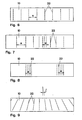
- the composite plate 10 shown in Fig. 6 usually has moderate distances a notches 22 shown in dashed lines. These notches have been pressed in to the same depth by the same pressing tool. The parallel notches extend over the entire width of the composite plate 10.
- FIG. 6 results in a composite plate 10 curved with a regular bending radius, as is shown in principle in FIG. 4.
- the indentations 22 are formed deeper in the central region. In this case, there is a greater bending of the composite panel 10 in the middle region mentioned than on the outside.
- the notches 22 have a smaller distance a in the central area than in the outer area. This results in a composite panel 10, which is more bent in the central area than outside. This difference with respect to the bend can be further increased by the indentations 22 being made deeper in the central region.
- a corrugated composite plate 10 is formed.
- the notches 22 on the upper and the lower cover layer of the composite plate 10 must not overlap, i.e. they must be offset in the longitudinal direction, because otherwise the effects cancel each other out and the risk of overstressing is greatly increased.
- the composite plate 10 shown in FIG. 8 shows notches 22 made in packages at a regular distance a.
- the notches 22 shown in broken lines are on the upper cover layer, the notches 22 shown in dotted lines are on the lower cover layer.
- a substantially U-shaped design of the composite profile could be achieved if both packs of notches 22 were arranged on the upper or on the lower cover layer.
Landscapes
- Engineering & Computer Science (AREA)
- Architecture (AREA)
- Mechanical Engineering (AREA)
- Civil Engineering (AREA)
- Structural Engineering (AREA)
- Shaping Of Tube Ends By Bending Or Straightening (AREA)
- Laminated Bodies (AREA)
Applications Claiming Priority (2)
| Application Number | Priority Date | Filing Date | Title |
|---|---|---|---|
| CH374889A CH678411A5 (fr) | 1989-10-13 | 1989-10-13 | |
| CH3748/89 | 1989-10-13 |
Publications (2)
| Publication Number | Publication Date |
|---|---|
| EP0423073A1 true EP0423073A1 (fr) | 1991-04-17 |
| EP0423073B1 EP0423073B1 (fr) | 1995-03-15 |
Family
ID=4262641
Family Applications (1)
| Application Number | Title | Priority Date | Filing Date |
|---|---|---|---|
| EP19900810765 Expired - Lifetime EP0423073B1 (fr) | 1989-10-13 | 1990-10-05 | Procédé pour courber un stratifié plat |
Country Status (4)
| Country | Link |
|---|---|
| EP (1) | EP0423073B1 (fr) |
| CA (1) | CA2027342A1 (fr) |
| CH (1) | CH678411A5 (fr) |
| DE (1) | DE59008705D1 (fr) |
Cited By (1)
| Publication number | Priority date | Publication date | Assignee | Title |
|---|---|---|---|---|
| NL1002541C2 (nl) * | 1996-03-06 | 1997-09-09 | Unfolding V O F | Werkwijze voor het voorbewerken van metaal/kunststof sandwichmateriaal ter vervaardiging daaruit van driedimensionale voorwerpen. |
Families Citing this family (2)
| Publication number | Priority date | Publication date | Assignee | Title |
|---|---|---|---|---|
| DE59611262D1 (de) * | 1996-07-18 | 2005-09-29 | Alcan Tech & Man Ag | Verbundplatte |
| US20200154714A1 (en) * | 2018-11-20 | 2020-05-21 | Canine Professional Services, Inc. | Anti microbial panels |
Citations (2)
| Publication number | Priority date | Publication date | Assignee | Title |
|---|---|---|---|---|
| DE2049304A1 (de) * | 1970-10-07 | 1972-04-13 | Westag & Getalit AG, 4832 Wiedenbrück | Mindestens einseitig mit Kunststoffbeschichtete, großflächige, in einer Richtung gewölbte Trägerplatte und Verfahren zu ihrer Herstellung |
| FR2370562A1 (fr) * | 1976-11-10 | 1978-06-09 | Bedouin Michel | Procede de pliage du bois par mise en forme des fibres dans la zone consideree |
-
1989
- 1989-10-13 CH CH374889A patent/CH678411A5/de not_active IP Right Cessation
-
1990
- 1990-10-05 EP EP19900810765 patent/EP0423073B1/fr not_active Expired - Lifetime
- 1990-10-05 DE DE59008705T patent/DE59008705D1/de not_active Expired - Fee Related
- 1990-10-11 CA CA 2027342 patent/CA2027342A1/fr not_active Abandoned
Patent Citations (2)
| Publication number | Priority date | Publication date | Assignee | Title |
|---|---|---|---|---|
| DE2049304A1 (de) * | 1970-10-07 | 1972-04-13 | Westag & Getalit AG, 4832 Wiedenbrück | Mindestens einseitig mit Kunststoffbeschichtete, großflächige, in einer Richtung gewölbte Trägerplatte und Verfahren zu ihrer Herstellung |
| FR2370562A1 (fr) * | 1976-11-10 | 1978-06-09 | Bedouin Michel | Procede de pliage du bois par mise en forme des fibres dans la zone consideree |
Cited By (2)
| Publication number | Priority date | Publication date | Assignee | Title |
|---|---|---|---|---|
| NL1002541C2 (nl) * | 1996-03-06 | 1997-09-09 | Unfolding V O F | Werkwijze voor het voorbewerken van metaal/kunststof sandwichmateriaal ter vervaardiging daaruit van driedimensionale voorwerpen. |
| EP0794041A1 (fr) * | 1996-03-06 | 1997-09-10 | Unfolding v.o.f. | Procédé de fabrication d'un objet tridimensionnel à partir d'un panneau sandwich |
Also Published As
| Publication number | Publication date |
|---|---|
| DE59008705D1 (de) | 1995-04-20 |
| EP0423073B1 (fr) | 1995-03-15 |
| CH678411A5 (fr) | 1991-09-13 |
| CA2027342A1 (fr) | 1991-04-14 |
Similar Documents
| Publication | Publication Date | Title |
|---|---|---|
| DE3803062C2 (fr) | ||
| DE69102000T2 (de) | Rohr und Verfahren zur Herstellung. | |
| DE2703694A1 (de) | Verfahren und vorrichtungen zur herstellung von mit rippen versehenen metallprofilen und durch dieses verfahren hergestellte profile | |
| EP2177702A1 (fr) | Profilé creux, notamment tuyau d'écartement pour un vitrage isolant et dispositif et procédé de fabrication du profilé creux | |
| EP0436058B1 (fr) | Procédé pour la fabrication de plaques en plastique avec des protubérances et plaque en plastique avec des protubérances | |
| DE10326554A1 (de) | Verfahren zum Herstellen einer Stossstangenverstärkung | |
| EP0424312A1 (fr) | Stratifié flexible | |
| DE2953278C2 (fr) | ||
| DE102007051354B4 (de) | Verfahren zum Herstellen eines Profils aus flachem Metallband | |
| DE69603623T2 (de) | Verfahren zur reparatur der lokalen schäden | |
| DE2044696C2 (de) | Vorrichtung zum kontinuierlichen Herstellen einer planen Verbundbahn | |
| EP0031822B1 (fr) | Procede de cintrage des toles et dispositif de mise en oeuvre | |
| EP2455169B1 (fr) | Procédé de transformation d'un matériau en forme de plaque en un objet tridimensionnel | |
| EP0579007A2 (fr) | Grillage d'armature pour couches d'enduit de bâtiments | |
| EP0423073B1 (fr) | Procédé pour courber un stratifié plat | |
| DE3501233A1 (de) | Verfahren zur herstellung eines mehrteiligen profilrahmens | |
| DE3315069C2 (de) | Verbundprofil, insbesondere für Fenster und Türen, Verfahren zur Herstellung des Verbundprofiles sowie Werkzeug zur Durchführung des Verfahrens | |
| DE69815790T2 (de) | Verfahren und Vorrichtung zum Formen einer Seitenwand an eine Grundplatte | |
| EP1372877B1 (fr) | Procede et dispositif d'extrusion notamment destines a la fabrication de produits extrudes courbes | |
| DE3300017A1 (de) | Flachkammer-waermetauscher sowie verfahren und vorrichtung zu dessen herstellung | |
| EP0545100B1 (fr) | Dispositif pour cintrer des tôles à ondes trapézoidales | |
| DE2438595A1 (de) | Band mit durchbruechen | |
| EP0294507A1 (fr) | Procédé et dispositif pour la production de bandes avec des protubérances, bandes fabriquées selon ce procédé et leur application | |
| DE4339962A1 (de) | Vorrichtung und Verfahren zur Herstellung von Sickenblechen mit planparallelen Außenkantenflächen | |
| DE2359308A1 (de) | Verfahren zum herstellen eines metallstreifens mit einem laengskanal |
Legal Events
| Date | Code | Title | Description |
|---|---|---|---|
| PUAI | Public reference made under article 153(3) epc to a published international application that has entered the european phase |
Free format text: ORIGINAL CODE: 0009012 |
|
| AK | Designated contracting states |
Kind code of ref document: A1 Designated state(s): AT BE CH DE DK ES FR GB IT LI LU NL SE |
|
| 17P | Request for examination filed |
Effective date: 19910911 |
|
| 17Q | First examination report despatched |
Effective date: 19921221 |
|
| RBV | Designated contracting states (corrected) |
Designated state(s): CH DE LI |
|
| GRAA | (expected) grant |
Free format text: ORIGINAL CODE: 0009210 |
|
| AK | Designated contracting states |
Kind code of ref document: B1 Designated state(s): CH DE LI |
|
| REF | Corresponds to: |
Ref document number: 59008705 Country of ref document: DE Date of ref document: 19950420 |
|
| PLBE | No opposition filed within time limit |
Free format text: ORIGINAL CODE: 0009261 |
|
| STAA | Information on the status of an ep patent application or granted ep patent |
Free format text: STATUS: NO OPPOSITION FILED WITHIN TIME LIMIT |
|
| 26N | No opposition filed | ||
| PGFP | Annual fee paid to national office [announced via postgrant information from national office to epo] |
Ref country code: CH Payment date: 20001030 Year of fee payment: 11 |
|
| PGFP | Annual fee paid to national office [announced via postgrant information from national office to epo] |
Ref country code: DE Payment date: 20001106 Year of fee payment: 11 |
|
| PG25 | Lapsed in a contracting state [announced via postgrant information from national office to epo] |
Ref country code: LI Free format text: LAPSE BECAUSE OF NON-PAYMENT OF DUE FEES Effective date: 20011031 Ref country code: CH Free format text: LAPSE BECAUSE OF NON-PAYMENT OF DUE FEES Effective date: 20011031 |
|
| REG | Reference to a national code |
Ref country code: CH Ref legal event code: PL |
|
| PG25 | Lapsed in a contracting state [announced via postgrant information from national office to epo] |
Ref country code: DE Free format text: LAPSE BECAUSE OF NON-PAYMENT OF DUE FEES Effective date: 20020702 |