EP0423196B1 - Kupplung mit gemischtem gewinde für verstärkte leitung - Google Patents
Kupplung mit gemischtem gewinde für verstärkte leitung Download PDFInfo
- Publication number
- EP0423196B1 EP0423196B1 EP89908060A EP89908060A EP0423196B1 EP 0423196 B1 EP0423196 B1 EP 0423196B1 EP 89908060 A EP89908060 A EP 89908060A EP 89908060 A EP89908060 A EP 89908060A EP 0423196 B1 EP0423196 B1 EP 0423196B1
- Authority
- EP
- European Patent Office
- Prior art keywords
- threads
- pipe
- scribed
- crests
- male
- Prior art date
- Legal status (The legal status is an assumption and is not a legal conclusion. Google has not performed a legal analysis and makes no representation as to the accuracy of the status listed.)
- Expired - Lifetime
Links
- 230000008878 coupling Effects 0.000 title description 23
- 238000010168 coupling process Methods 0.000 title description 23
- 238000005859 coupling reaction Methods 0.000 title description 23
- 239000002131 composite material Substances 0.000 title 1
- 229920005989 resin Polymers 0.000 claims description 17
- 239000011347 resin Substances 0.000 claims description 17
- 238000005520 cutting process Methods 0.000 claims description 11
- 239000000835 fiber Substances 0.000 claims description 9
- 239000004033 plastic Substances 0.000 claims description 7
- 229920003002 synthetic resin Polymers 0.000 claims description 7
- 239000000057 synthetic resin Substances 0.000 claims description 7
- 239000000945 filler Substances 0.000 claims description 4
- 230000009467 reduction Effects 0.000 claims description 4
- 230000001747 exhibiting effect Effects 0.000 claims 3
- 239000011152 fibreglass Substances 0.000 abstract description 18
- 230000013011 mating Effects 0.000 abstract description 6
- 230000002787 reinforcement Effects 0.000 description 11
- 230000008901 benefit Effects 0.000 description 10
- 239000000463 material Substances 0.000 description 9
- 238000000034 method Methods 0.000 description 6
- 230000015572 biosynthetic process Effects 0.000 description 4
- 239000011521 glass Substances 0.000 description 4
- OKTJSMMVPCPJKN-UHFFFAOYSA-N Carbon Chemical compound [C] OKTJSMMVPCPJKN-UHFFFAOYSA-N 0.000 description 2
- CWYNVVGOOAEACU-UHFFFAOYSA-N Fe2+ Chemical compound [Fe+2] CWYNVVGOOAEACU-UHFFFAOYSA-N 0.000 description 2
- 229910000831 Steel Inorganic materials 0.000 description 2
- 229910052799 carbon Inorganic materials 0.000 description 2
- 230000007797 corrosion Effects 0.000 description 2
- 238000005260 corrosion Methods 0.000 description 2
- 229920000728 polyester Polymers 0.000 description 2
- 239000000843 powder Substances 0.000 description 2
- 230000008569 process Effects 0.000 description 2
- 239000010959 steel Substances 0.000 description 2
- 241000208140 Acer Species 0.000 description 1
- 230000001464 adherent effect Effects 0.000 description 1
- 239000000853 adhesive Substances 0.000 description 1
- 230000001070 adhesive effect Effects 0.000 description 1
- 238000012993 chemical processing Methods 0.000 description 1
- 239000003795 chemical substances by application Substances 0.000 description 1
- 230000008602 contraction Effects 0.000 description 1
- 238000007598 dipping method Methods 0.000 description 1
- 239000003365 glass fiber Substances 0.000 description 1
- 230000002706 hydrostatic effect Effects 0.000 description 1
- 230000006872 improvement Effects 0.000 description 1
- 238000005304 joining Methods 0.000 description 1
- 239000002648 laminated material Substances 0.000 description 1
- 238000004519 manufacturing process Methods 0.000 description 1
- 239000002184 metal Substances 0.000 description 1
- 239000002991 molded plastic Substances 0.000 description 1
- 210000002445 nipple Anatomy 0.000 description 1
- 238000010422 painting Methods 0.000 description 1
- 238000012545 processing Methods 0.000 description 1
- 239000002990 reinforced plastic Substances 0.000 description 1
- 238000000926 separation method Methods 0.000 description 1
- 238000005507 spraying Methods 0.000 description 1
- 239000000758 substrate Substances 0.000 description 1
Images

Classifications
-
- F—MECHANICAL ENGINEERING; LIGHTING; HEATING; WEAPONS; BLASTING
- F16—ENGINEERING ELEMENTS AND UNITS; GENERAL MEASURES FOR PRODUCING AND MAINTAINING EFFECTIVE FUNCTIONING OF MACHINES OR INSTALLATIONS; THERMAL INSULATION IN GENERAL
- F16L—PIPES; JOINTS OR FITTINGS FOR PIPES; SUPPORTS FOR PIPES, CABLES OR PROTECTIVE TUBING; MEANS FOR THERMAL INSULATION IN GENERAL
- F16L15/00—Screw-threaded joints; Forms of screw-threads for such joints
- F16L15/001—Screw-threaded joints; Forms of screw-threads for such joints with conical threads
-
- F—MECHANICAL ENGINEERING; LIGHTING; HEATING; WEAPONS; BLASTING
- F16—ENGINEERING ELEMENTS AND UNITS; GENERAL MEASURES FOR PRODUCING AND MAINTAINING EFFECTIVE FUNCTIONING OF MACHINES OR INSTALLATIONS; THERMAL INSULATION IN GENERAL
- F16L—PIPES; JOINTS OR FITTINGS FOR PIPES; SUPPORTS FOR PIPES, CABLES OR PROTECTIVE TUBING; MEANS FOR THERMAL INSULATION IN GENERAL
- F16L15/00—Screw-threaded joints; Forms of screw-threads for such joints
- F16L15/04—Screw-threaded joints; Forms of screw-threads for such joints with additional sealings
-
- F—MECHANICAL ENGINEERING; LIGHTING; HEATING; WEAPONS; BLASTING
- F16—ENGINEERING ELEMENTS AND UNITS; GENERAL MEASURES FOR PRODUCING AND MAINTAINING EFFECTIVE FUNCTIONING OF MACHINES OR INSTALLATIONS; THERMAL INSULATION IN GENERAL
- F16L—PIPES; JOINTS OR FITTINGS FOR PIPES; SUPPORTS FOR PIPES, CABLES OR PROTECTIVE TUBING; MEANS FOR THERMAL INSULATION IN GENERAL
- F16L47/00—Connecting arrangements or other fittings specially adapted to be made of plastics or to be used with pipes made of plastics
- F16L47/16—Screw-threaded joints
Definitions
- the invention relates to couplings for non-ferrous pipe (or tubing) of plastic or fiberglass, for example. More particularly, the invention relates to glass reinforced resin pipe having premolded or contact molded end portions (male and female threads) for joining the end portions together.
- Resin pipe reinforced with glass filamentous material is well known to the art and possesses a number of advantages over metal pipe, e.g., inertness, low weight, corrosive resistance, and high strength. These properties make such pipes particularly suitable for use in the chemical processing industry and in the oil industry for use as line pipe, down hole tubing, etc.
- Threaded end portions of glass reinforced resin pipes have been formed by a number of methods.
- One method employs the use of discrete coupling members (bonded to the pipes) providing threaded adjacent ends to the pipes to be joined.
- discrete coupling members bonded to the pipes
- the possibility for leakage is doubled.
- time and effort necessary for assembly is increased as well as the possibility for damage during assembly.
- threaded pipe end portions is a considerable improvement over the employment of discrete coupling members.
- the formation of threaded end portions simultaneously with the formation of the pipe by virtue of a threaded coupling-like member over the end portion of a rotatable mandrel, for example is also subject to some disadvantages. For example, care must be taken to avoid the entrapment of air in the resin in the formation of the threads and to assure uniform and complete filling of the threads. Thus, an extra step is introduced into the formation of the pipe.
- the application of release agents to the threaded nipple end must also be carefully applied to insure a good release of the thread and further to prevent any damage to the threads when the finished pipe is removed from the mandrel.
- Another method involves scribing grooves in a finished pipe to form threads therein. Although this is a workable arrangement, it is not without drawbacks.
- the scribing procedure results in broken reinforcement threads and exposed fiberglass strands in the pipe.
- a joint having scribed grooves on the mating male and female members provides the distinct benefit of enhanced tensile strength in the area of the coupling when compared to coupling elements bonded or otherwise molded to the fiberglass pipe.
- the scribed grooves of a male/female coupling provide a direct mechanical interlock between the substrates of the joined pipes.
- Such pipes possess increased tensile strength in the coupling portion which corresponds to the relatively greater interlaminar shear strength of a scribed thread compared to a molded thread.
- Scribed threads are ground into the pipe laminate and necessarily involve excess resin material (for the amount ground away).
- the grinding and scribing processes applied may involve broken or cut threads or exposed fiberglass strands and the potential rejection of the thread after the entire pipe has been formed.
- the ground or scribed male and female thread joint provides the distinct advantage of a mechanical interlock tied integrally to the pipe laminate.
- the interlaminar shear strength of ground threads is recognized to be relatively greater than that of paste or molded threads whereby the corresponding tensile strength of the joint is enhanced.
- paste or contact molded threads formed on the pipe laminate ends to be joined certain advantages and disadvantages also exist.
- the primary disadvantage resides in the fact that a paste or molded thread does not provide mechanical interlock between the joined pipe laminates because only an adhesive bond exists between the paste threads and the pipe laminate.
- the paste or molded threads provide a more consistent thread profile with a corresponding relatively smooth finish, resulting in relatively lower engagement, and more significantly disengagement, torque requirements.
- the paste or molded thread has less of a tendency to powder during engagement than does the relatively rough surface of a thread scribed into the pipe laminate material.
- a paste or molded thread includes a more random orientation of reinforcement materials when compared to the reinforcement strands or threads which may be cut in the pipe laminate during grinding of a scribed thread.
- a random orientation of reinforcement materials with respect to the shear plane of the scribed threads results in a relatively stronger joint.
- the above considerations are important in considering the application and use of the joint. For example, in an oil field situation utilizing a string of fiberglass pipes or tubes, it is obviously important that sufficient interlaminar shear strength exist at a joint. Put another way, it is important that the overall tensile strength of a pipe string not be unduly limited by potential separation of any one joint during use of the string.
- the tensile strength of the joints is also of significance in a horizontal pipe application.
- a horizontal pipe typically will have a hydrostatic pressure associated with it which develops an end load on a pipe string which in turn exerts a tensile force on the pipe joints in an axial direction.
- the tensile or axial force considerations in both a vertical and horizontal pipe string are the same with respect to the present invention.
- the US-A-3101207 discloses a gas-tight and readily separable tube connection comprising threaded tubes, for example made of plastic, having on threads of at least one of said tubes an adherent hardened layer.
- This layer consists of a synthetic resin hardenable without giving off volatile components and processing a sufficient hardness and elasticity. Its application may be accomplished in any desired manner, for example by dipping, painting with a brush, spraying or with a putty knife. Its thickness may vary within wide limits and depends, among other factors, upon the diameter of the tubes.
- the problem of the US-A-3101207 is to produce gas-tight and easily joinable and separable threaded tube connections the layer has to be flexible after hardening.
- an object of the present invention is to provide an improved coupling for joined fiberglass pipe sections in the sense that the joint will have significantly improved tensile strength in an axial direction when compared to certain prior art couplings.
- Another object of the present invention is to provide a fiberglass pipe coupling which includes enhanced tensile strength as referred to above and which further includes the benefits of a paste thread interface on the male/female coupling surfaces.
- a still further object of the present invention is to provide the aforesaid coupling in a manner which can be easily made a part of the fabrication process for fiberglass pipe.
- the present invention provides for scribed or ground male and female threads on adjacent ends of two fiberglass pipe sections to be joined. At least one of the scribed threaded surfaces has a paste thread contact molded thereon so that the root or base of the paste thread is below the crest of the ground thread to which it is molded. The pitch of the contact molded thread is the same as the ground thread to which it mates.
- the paste thread surface Upon mating off the coupled pipe ends, the paste thread surface provides the advantages enumerated above while also providing a mechanical interlock between the pipe sections. Mechanical interlock results from the overlapped projections of the male and female threads ground into the fiberglass pipes.
- the paste thread may be provided on either the maple or female portion of the coupling.
- a paste thread may be formed on both the male and female scribed portions of the coupling.
- the root or base of the paste threads on each joint portion are below the crest of the ground threads to which they are molded.
- the aforesaid paste thread on a fiberglass pipe could be directly joined with the mating end of a steel or metallic pipe having integrally ground threads.
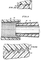
- FIGURE 1 is a longitudinal view in cross section of two fiber reinforced pipe ends having a male and female portion for coupling the same together.
- the female portion includes threads ground directly into the pipe laminate.
- the male portion has paste threads contact molded onto threads which are also scribed into the pipe laminate.
- FIGURE 1A is an enlarged, isolated view of the thread engagement illustrated in Figure 1.
- FIGURE 2 is a view similar to Figure 1 with the contact molded paste threads being placed on the female portion of the coupling instead of the male portion.
- FIGURE 2A is an enlarged, isolated view of the thread engagement illustrated in Figure 2.
- FIGURE 3 is a longitudinal view in cross section of two fiber reinforced pipe ends having a male and female portion for coupling the same together. Each portion includes threads ground directly into the pipe laminate with paste threads contact molded to the threads scribed into the respective pipe laminates.
- FIGURE 3A is an enlarged, isolated view of the thread engagement illustrated in Figure 3.
- Pipe joint 10 in Figure 1 is provided for connecting the ends of a pair of non-ferrous (e.g., fiberglass or plastic) pipe sections 12 and 14.
- the pipe sections have tapered ends as shown and correspondingly tapered male and female coupling portions.
- Each pipe section 12 and 14 is formed of resin including embedded strands of glass filaments (for example) for reinforcement purposes, as is well known in the art.
- the reinforcement filaments could also be carbon, polyester or other functionally equivalent materials.
- female threads are ground into the laminate body of pipe 12 and may, for example, have an eight round thread as is widely used in such fiberglass pipe applications.
- threads are also scribed into the laminate body of the pipe and include a pitch corresponding to that on the female pipe coupling portion.
- the ground threads on pipe portion 14 are in turn provided with an overlying paste thread or contact molded thread 16 which includes the same pitch as the threads scribed into the resin pipe bodies.
- the contact molded thread 16 is preferably formed of the same resin that is used to fabricate pipe body 14. With the molded thread 16 bonded to pipe body 14, and both being formed of the same resin material, thermal expansion and contraction is easily accommodated since there is no rate differential.
- the paste thread 16 has filler material in it to control viscosity and chopped fibers to provide further reinforcement to the thread 16.
- the chopped fibers in the plastic thread 16 are randomly oriented as opposed to the wound reinforcement filaments in the fiberglass pipe bodies.
- the crest of the threads scribed into each of the joined fiberglass pipes overlap one another and provide a mechanical interlock with the reinforced plastic thread 16 being sandwiched therebetween.
- the ground threads are relatively shallow in order to minimize the cutting of the wound reinforcement threads or filaments in each of the pipe sections.
- the reduction in reinforcement provided to the pipe body is minimized, and the wasted material of the pipe body due to grinding is minimized.
- the provision of the contact molded thread surface provides for a more consistent, smooth thread engagement surface. This in turn translates into a relatively lower engagement and disengagement torque than would be the case, for example, if a ground thread were engaged with another ground thread.
- a smoother thread surface there is also a reduced tendency of the paste thread to powder or abrade when compared to the relatively abrasive surface of the ground thread if it were engaged with another ground thread.
- Figures 2 and 2A show another embodiment of the present invention with the female portion 18 of the joint having a contact molded thread surface 20 over the female threads ground into the pipe body 18.
- the male pipe portion 22 only has threads ground into the pipe body. All of the same considerations applicable to the embodiment illustrated in Figures 1 and 1A apply to the embodiment illustrated in Figures 2 and 2A.
- FIGS 3 and 3A illustrate yet another embodiment of the present invention.
- both the female pipe coupling portion 24 and the male portion 26 have threads of resin material molded to the threads scribed into the respective pipe bodies.
- the contact molded threads are designated at 28 on female portion 24 and at 30 on male portion 26.
- Figures 3 and 3A would be used where relatively close thread tolerances are required and in difficult field applications for example where relatively lower engagement and disengagement torques might be desired.
- Figure 3 embodiment could be utilized when it is desired to have increased corrosion resistance since the molded paste thread surface is more effective in resisting corrosion than is the surface provided by threads scribed into the pipe body.
- Figure 3 embodiment as in the Figure 1 and Figure 2 embodiments, has as its principal advantage the mechanical interlock provided by the overlapping crests on the threads scribed into each of the coupled pipe bodies and the desirable characteristics associated with the contact molded thread surface as considered above.
- a fiber reinforced pipe having a scribed thread end with a contact molded paste thread thereover could be directly joined to a steel or metallic pipe end.
- the metallic pipe would have mating integrally ground threads whereby the mechanical overlap and associated benefits described above would exist.
Landscapes
- Engineering & Computer Science (AREA)
- General Engineering & Computer Science (AREA)
- Mechanical Engineering (AREA)
- Rigid Pipes And Flexible Pipes (AREA)
- Non-Disconnectible Joints And Screw-Threaded Joints (AREA)
- Mutual Connection Of Rods And Tubes (AREA)
Claims (3)
- Aus Kunststoff hergestellte Rohrleitung mit einem Außengewindeendabschnitt, der geeignet ist zum Herstellen einer eine höhere Zugspannung gewährleistenden Verbindung mit einem Innengewindeelement und einer Schicht aus einem synthetischen Harz auf dem Außengewinde, das ausreichend dünn ist, um sicherzustellen, daß die Kehlen der Schicht sich unter die Spitzen des Außengewindes erstrecken, damit sich die Spitzen des Gewindes auf einem Innengewindeelement unter die Spitzen des Außengewindes erstrecken, nachdem die Rohrleitung mit dem Innengewindeelement gewindemäßig verbunden worden ist, wobei das synthetische Harz ein Füllmittel enthält,
dadurch gekennzeichnet, daß
die Rohrleitung aus mit gewundenen Fäden verstärktem Harz hergestellt ist, das Außengewinde flach in die äußere Oberfläche des Endabschnittes der Rohrleitung eingeritzt und geschnitten ist, wodurch ein Schneiden der gewundenen Fasern minimiert wird und die Festigkeit des Körpers der Rohrleitung durch Schneiden auf eine Tiefe beibehalten wird, die ausreichend ist, damit die Spitzen des Gewindes auf dem Innengewindeelement, dessen Gewinde dieselbe Steigung wie das Gewinde auf dem Außengewindeelement hat, die Spitzen des eingeritzten Außengewindes überlappen können, nachdem die Rohrleitung gewindemäßig an dem Innengewindeelement befestigt worden ist, jedoch nicht tief genug, um ein signifikantes Schneiden der gewundenen Fasern und eine resultierende Reduzierung in der Zugfestigkeit der Verbindung zu bewirken, die Schicht als glattes, kontaktangegossenes Gewinde ausgebildet ist, das aus demselben Harz wie die Rohrleitung hergestellt ist, und zwar ausschließlich der gewundenen Fasern darin, und mit zufällig ausgerichteten geschnittenen Fasern verstärkt ist, die eine Deckschicht über dem eingeschnittenen Gewinde bildet und etwa dieselbe Steigung wie das eingeschnittene Gewinde hat, wobei das kontaktangegossene Gewinde dieselben thermischen Expansionscharakteristiken hat wie die Rohrleitung, sowie eine konsistente und kontrollierte Dicke, so daß sie ausreichend dick sind, um eine konsistente glatte Gewindeeingriffsfläche zu schaffen. - Aus Kunststoff hergestellte Rohrleitung mit einem Innengewindeendabschnitt, die geeignet ist zum Herstellen einer eine höhere Zugfestigkeit aufweisenden Verbindung mit einem Außengewindeelement und einer Schicht aus einem synthetischen Harz auf dem Innengewinde, die ausreichend dünn ist, um sicherzustellen, daß die Kehlen der Schicht sich unter die Spitzen des Innengewindes erstrecken, damit sich die Spitzen des Gewindes auf dem Außengewinde unter die Spitzen des Außengewindes erstrecken, nachdem die Rohrleitung an dem Gewindeelement angeschraubt worden ist, wobei das synthetische Harz einen Füller enthält,
dadurch gekennzeichnet, daß
die Rohrleitung aus mit gewundenen Fasern verstärktem Harz hergestellt ist, das Innengewinde flach in die äußere Oberfläche des Endabschnittes der Leitung eingeritzt und geschnitten ist, wodurch ein Schneiden der gewundenen Fasern minimiert wird und die Festigkeit des Körpers der Rohrleitung durch Schneiden bis zu einer Tiefe beibehalten wird, die ausreichend ist, damit die Spitzen des Gewindes auf dem Außengewindeelement, dessen Gewinde dieselbe Steigung wie das Gewinde des Innenelementes aufweist, die Spitzen des eingeschnittenen Innengewindes überlappt, nachdem die Rohrleitung an dem Außengewindeelement angeschraubt worden ist, jedoch nicht tief genug, um ein signifikantes Schneiden der gewundenen Fasern und der resultierenden Reduzierung der Zugfestigkeit der Verbindung zu bewirken, die Schicht als glattes kontaktangegossenes Gewinde ausgebildet ist, das aus demselben Harz wie die Rohrleitung hergestellt ist, und zwar ausschließlich der gewundenen Fasern darin, und mit zufällig ausgerichteten geschnittenen Fasern verstärkt ist, die eine Deckschicht über das eingeschnittene Gewinde bildet und etwa dieselbe Steigung wie das eingeschnittene Gewinde haben, wobei das kontaktangegossene Gewinde dieselben thermischen Expansionskoeffizienten wie die Rohrleitung sowie eine konsistente und kontrollierte Dicke hat, sodaß sie ausreichend dick sind, um eine konsistente glatte Gewindeeingriffsfläche zu schaffen. - Aus Kunststoff hergestellte erste und zweite Rohrleitungen mit jeweils einem Außengewinde- und einem Innengewindeendabschnitt, die geeignet sind zum Herstellen einer eine höhere Zugfestigkeit zueinander aufweisende Verbindung, und eine Schicht aus einem synthetischen Harz auf dem Gewinde, die ausreichend dünn ist, um sicherzustellen, daß die Kehlen der Schicht sich unter die Spitzen des Gewindes derselben Rohrleitung erstrecken und die Spitzen des Gewindes auf jeder Rohrleitung sich unter die Spitzen des Gewindes der anderen Rohrleitung erstrecken, nachdem die Rohrleitungen gewindemäßig miteinander verbunden worden sind, wobei das synthetische Harz ein Füllmittel enthält,
dadurch gekennzeichnet, daß
die Rohrleitungen aus mit gewundenen Fasern verstärktem Harz herstellt sind, die Gewinde flach in die äußere Oberfläche der Endabschnitte der Rohrleitungen eingeritzt und geschnitten sind und etwa dieselbe Steigung haben, wodurch ein Schneiden der gewundenen Fasern minimiert wird und die Festigkeit des Körpers der Rohrleitungen durch Schneiden bis zu einer Tiefe beibehalten wird, die ausreichend ist, um sicherzustellen, daß die Spitzen des eingeritzten Gewindes sich einander überlappen, nachdem die Rohrleitungen zusammengeschraubt worden ist, jedoch nicht tief genug, um ein signifikantes Schneiden der gewundenen Fasern und eine resultierende Reduzierung der Zugfestigkeit der Verbindung zu bewirken,
die Schicht aus glattem kontaktangegossenen hergestellten Gewinde besteht, das aus demselben Harz wie die Rohrleitungen hergestellt ist, ausschließlich der gewundenen Fasern darin, und mit zufällig ausgerichteten geschnittenen Fasern verstärkt ist, die eine Deckschicht über das eingeschnittene Gewinde bildet und etwa dieselbe Steigung wie das eingeschnittene Gewinde aufweist, wobei das kontaktangegossene Gewinde dieselben thermischen Expansionscharakteristiken wie die Rohrleitungen sowie eine konsistente und kontrollierte Dicke aufweist, so daß es ausreichend dick ist, um eine konsistente glatte Gewindeeingriffsfläche zu schaffen.
Applications Claiming Priority (3)
| Application Number | Priority Date | Filing Date | Title |
|---|---|---|---|
| US21259988A | 1988-06-28 | 1988-06-28 | |
| US212599 | 1988-06-28 | ||
| PCT/US1989/002790 WO1990000236A1 (en) | 1988-06-28 | 1989-06-28 | Composite thread coupling for reinforced pipe |
Publications (3)
| Publication Number | Publication Date |
|---|---|
| EP0423196A1 EP0423196A1 (de) | 1991-04-24 |
| EP0423196A4 EP0423196A4 (en) | 1991-11-21 |
| EP0423196B1 true EP0423196B1 (de) | 1994-06-22 |
Family
ID=22791693
Family Applications (1)
| Application Number | Title | Priority Date | Filing Date |
|---|---|---|---|
| EP89908060A Expired - Lifetime EP0423196B1 (de) | 1988-06-28 | 1989-06-28 | Kupplung mit gemischtem gewinde für verstärkte leitung |
Country Status (4)
| Country | Link |
|---|---|
| EP (1) | EP0423196B1 (de) |
| CA (1) | CA1307750C (de) |
| DE (1) | DE68916428T2 (de) |
| WO (1) | WO1990000236A1 (de) |
Families Citing this family (6)
| Publication number | Priority date | Publication date | Assignee | Title |
|---|---|---|---|---|
| WO1991018733A1 (en) * | 1990-06-01 | 1991-12-12 | A.O. Smith Corporation | Method of joining threaded non-ferrous pipe sections |
| US5360240A (en) * | 1993-03-05 | 1994-11-01 | Hydril Company | Method of connecting plastic pipe joints to form a liner for an existing pipeline and a plastic pipe joint for forming such liner |
| JP2981393B2 (ja) * | 1994-01-11 | 1999-11-22 | 株式会社東海理化電機製作所 | バックル引込み装置 |
| FR2728049A1 (fr) * | 1994-12-08 | 1996-06-14 | Chevrier Gerard | Dispositif de raccordement d'une extremite d'un tube en matiere thermoplastique renforcee |
| FR2728051B1 (fr) * | 1994-12-08 | 1997-01-17 | Chevrier Gerard | Dispositif de raccordement pour tubes hautes pressions |
| NL2023274B1 (en) * | 2019-06-07 | 2021-01-11 | Itrec Bv | Tubular with screw thread |
Family Cites Families (7)
| Publication number | Priority date | Publication date | Assignee | Title |
|---|---|---|---|---|
| US658085A (en) * | 1900-01-04 | 1900-09-18 | Clinton A Higbee | Screw-coupling. |
| US2900435A (en) * | 1955-05-02 | 1959-08-18 | Thomas & Betts Corp | Electrical conduit bushing |
| US3101207A (en) * | 1958-07-26 | 1963-08-20 | Henkel & Cie Gmbh | Process for the production of gas-tight tube connections |
| US3366504A (en) * | 1964-03-30 | 1968-01-30 | Flambeau Plastics Corp | Threaded pipe fitting |
| US4033167A (en) * | 1974-08-21 | 1977-07-05 | General Signal Corporation | Process for forming intermediate metal conduit |
| US4154466A (en) * | 1977-01-03 | 1979-05-15 | Centron Corporation | Pipe section and coupling |
| US4537426A (en) * | 1982-06-24 | 1985-08-27 | Ameron Inc. | Couplings for non-ferrous pipe |
-
1989
- 1989-06-28 WO PCT/US1989/002790 patent/WO1990000236A1/en not_active Ceased
- 1989-06-28 CA CA000604262A patent/CA1307750C/en not_active Expired - Lifetime
- 1989-06-28 DE DE68916428T patent/DE68916428T2/de not_active Expired - Fee Related
- 1989-06-28 EP EP89908060A patent/EP0423196B1/de not_active Expired - Lifetime
Also Published As
| Publication number | Publication date |
|---|---|
| CA1307750C (en) | 1992-09-22 |
| EP0423196A1 (de) | 1991-04-24 |
| DE68916428T2 (de) | 1994-10-13 |
| EP0423196A4 (en) | 1991-11-21 |
| DE68916428D1 (de) | 1994-07-28 |
| WO1990000236A1 (en) | 1990-01-11 |
Similar Documents
| Publication | Publication Date | Title |
|---|---|---|
| US5106130A (en) | Composite thread coupling for reinforced pipe | |
| US3989280A (en) | Pipe joint | |
| US5281454A (en) | Closed composite sections with bonded scarf joints | |
| US4238540A (en) | Fiber reinforced composite shaft with metallic connector sleeves mounted by connector ring interlock | |
| CA1260981A (en) | Flange connection assembly for fiber-reinforced plastic pipe members | |
| EP0433686B1 (de) | Faserverstärktes Kunststoffrohr für geschraubte Rohrkupplungen | |
| CN1053036C (zh) | 纤维增强复合材料管接头和其组成的复合材料管 | |
| CA2081302C (en) | Filament wound threaded tube connector | |
| US3604461A (en) | Composite tubing | |
| CA1067538A (en) | Taper pipe joint | |
| US3483896A (en) | Composite reinforced plastic pipe | |
| CA1261897A (en) | Connector assembly for fiber-reinforced plastic pipe members | |
| US3673029A (en) | Method of making a threaded filament wound pipe | |
| US3388932A (en) | Joint for laminated articles | |
| EP0423196B1 (de) | Kupplung mit gemischtem gewinde für verstärkte leitung | |
| GB1599363A (en) | Fibre reinforced thermosetting resin pipe part | |
| US3572392A (en) | Threaded filament wound pipe and the method of manufacture thereof | |
| DE69214645T2 (de) | Mehrschichtiges rohr und verfahren zu seiner herstellung | |
| US3172934A (en) | Bonded coupling liner fabrication and installation process | |
| CN116857460A (zh) | 复合管材及复合管材的制作方法 | |
| CA1108071A (en) | Composite pipe having an integral bell end | |
| US11635105B2 (en) | Optimized thread profile for joining composite materials | |
| EP0036674A2 (de) | Verfahren zur Herstellung von Kunststoffrohren | |
| CN113089413B (zh) | 一种内嵌分布式光纤的智能传力杆及其制造方法 | |
| JPH0645757Y2 (ja) | 樹脂複合管継手 |
Legal Events
| Date | Code | Title | Description |
|---|---|---|---|
| PUAI | Public reference made under article 153(3) epc to a published international application that has entered the european phase |
Free format text: ORIGINAL CODE: 0009012 |
|
| 17P | Request for examination filed |
Effective date: 19910128 |
|
| AK | Designated contracting states |
Kind code of ref document: A1 Designated state(s): DE FR GB IT NL |
|
| A4 | Supplementary search report drawn up and despatched |
Effective date: 19910930 |
|
| AK | Designated contracting states |
Kind code of ref document: A4 Designated state(s): DE FR GB IT NL |
|
| 17Q | First examination report despatched |
Effective date: 19920514 |
|
| GRAA | (expected) grant |
Free format text: ORIGINAL CODE: 0009210 |
|
| AK | Designated contracting states |
Kind code of ref document: B1 Designated state(s): DE FR GB IT NL |
|
| ITF | It: translation for a ep patent filed | ||
| REF | Corresponds to: |
Ref document number: 68916428 Country of ref document: DE Date of ref document: 19940728 |
|
| ET | Fr: translation filed | ||
| PLBE | No opposition filed within time limit |
Free format text: ORIGINAL CODE: 0009261 |
|
| STAA | Information on the status of an ep patent application or granted ep patent |
Free format text: STATUS: NO OPPOSITION FILED WITHIN TIME LIMIT |
|
| 26N | No opposition filed | ||
| PGFP | Annual fee paid to national office [announced via postgrant information from national office to epo] |
Ref country code: FR Payment date: 20000621 Year of fee payment: 12 |
|
| PGFP | Annual fee paid to national office [announced via postgrant information from national office to epo] |
Ref country code: GB Payment date: 20000622 Year of fee payment: 12 |
|
| PGFP | Annual fee paid to national office [announced via postgrant information from national office to epo] |
Ref country code: NL Payment date: 20000627 Year of fee payment: 12 |
|
| PGFP | Annual fee paid to national office [announced via postgrant information from national office to epo] |
Ref country code: DE Payment date: 20000629 Year of fee payment: 12 |
|
| PG25 | Lapsed in a contracting state [announced via postgrant information from national office to epo] |
Ref country code: GB Free format text: LAPSE BECAUSE OF NON-PAYMENT OF DUE FEES Effective date: 20010628 |
|
| PG25 | Lapsed in a contracting state [announced via postgrant information from national office to epo] |
Ref country code: NL Free format text: LAPSE BECAUSE OF NON-PAYMENT OF DUE FEES Effective date: 20020101 |
|
| GBPC | Gb: european patent ceased through non-payment of renewal fee |
Effective date: 20010628 |
|
| PG25 | Lapsed in a contracting state [announced via postgrant information from national office to epo] |
Ref country code: FR Free format text: LAPSE BECAUSE OF NON-PAYMENT OF DUE FEES Effective date: 20020228 |
|
| NLV4 | Nl: lapsed or anulled due to non-payment of the annual fee |
Effective date: 20020101 |
|
| PG25 | Lapsed in a contracting state [announced via postgrant information from national office to epo] |
Ref country code: DE Free format text: LAPSE BECAUSE OF NON-PAYMENT OF DUE FEES Effective date: 20020403 |
|
| PG25 | Lapsed in a contracting state [announced via postgrant information from national office to epo] |
Ref country code: IT Free format text: LAPSE BECAUSE OF NON-PAYMENT OF DUE FEES;WARNING: LAPSES OF ITALIAN PATENTS WITH EFFECTIVE DATE BEFORE 2007 MAY HAVE OCCURRED AT ANY TIME BEFORE 2007. THE CORRECT EFFECTIVE DATE MAY BE DIFFERENT FROM THE ONE RECORDED. Effective date: 20050628 |