EP0423233B1 - Procede et dispositif de coulee en continu de bandes metalliques - Google Patents
Procede et dispositif de coulee en continu de bandes metalliques Download PDFInfo
- Publication number
- EP0423233B1 EP0423233B1 EP89908695A EP89908695A EP0423233B1 EP 0423233 B1 EP0423233 B1 EP 0423233B1 EP 89908695 A EP89908695 A EP 89908695A EP 89908695 A EP89908695 A EP 89908695A EP 0423233 B1 EP0423233 B1 EP 0423233B1
- Authority
- EP
- European Patent Office
- Prior art keywords
- strip
- cooling
- molten metal
- cooling member
- passage gap
- Prior art date
- Legal status (The legal status is an assumption and is not a legal conclusion. Google has not performed a legal analysis and makes no representation as to the accuracy of the status listed.)
- Expired - Lifetime
Links
- 239000002184 metal Substances 0.000 title claims abstract description 76
- 238000000034 method Methods 0.000 title claims abstract description 45
- 238000009749 continuous casting Methods 0.000 title claims description 8
- 238000001816 cooling Methods 0.000 claims abstract description 129
- 238000007711 solidification Methods 0.000 claims abstract description 50
- 230000008023 solidification Effects 0.000 claims abstract description 50
- 238000005266 casting Methods 0.000 claims abstract description 34
- 230000015572 biosynthetic process Effects 0.000 claims description 14
- 229910000831 Steel Inorganic materials 0.000 claims description 4
- 239000010959 steel Substances 0.000 claims description 4
- 239000007788 liquid Substances 0.000 abstract 1
- 239000000463 material Substances 0.000 description 5
- 239000000155 melt Substances 0.000 description 4
- 238000005304 joining Methods 0.000 description 3
- 238000004519 manufacturing process Methods 0.000 description 3
- 210000004894 snout Anatomy 0.000 description 3
- 239000002826 coolant Substances 0.000 description 2
- 230000003111 delayed effect Effects 0.000 description 2
- 238000002844 melting Methods 0.000 description 2
- 230000008018 melting Effects 0.000 description 2
- 238000012986 modification Methods 0.000 description 2
- 230000004048 modification Effects 0.000 description 2
- 238000004804 winding Methods 0.000 description 2
- 230000001419 dependent effect Effects 0.000 description 1
- 238000006073 displacement reaction Methods 0.000 description 1
- 238000005058 metal casting Methods 0.000 description 1
- 235000011837 pasties Nutrition 0.000 description 1
- 230000003746 surface roughness Effects 0.000 description 1
- 238000003466 welding Methods 0.000 description 1
Images




Classifications
-
- B—PERFORMING OPERATIONS; TRANSPORTING
- B22—CASTING; POWDER METALLURGY
- B22D—CASTING OF METALS; CASTING OF OTHER SUBSTANCES BY THE SAME PROCESSES OR DEVICES
- B22D11/00—Continuous casting of metals, i.e. casting in indefinite lengths
- B22D11/06—Continuous casting of metals, i.e. casting in indefinite lengths into moulds with travelling walls, e.g. with rolls, plates, belts, caterpillars
- B22D11/0637—Accessories therefor
- B22D11/064—Accessories therefor for supplying molten metal
- B22D11/0642—Nozzles
-
- B—PERFORMING OPERATIONS; TRANSPORTING
- B22—CASTING; POWDER METALLURGY
- B22D—CASTING OF METALS; CASTING OF OTHER SUBSTANCES BY THE SAME PROCESSES OR DEVICES
- B22D11/00—Continuous casting of metals, i.e. casting in indefinite lengths
- B22D11/06—Continuous casting of metals, i.e. casting in indefinite lengths into moulds with travelling walls, e.g. with rolls, plates, belts, caterpillars
- B22D11/0637—Accessories therefor
- B22D11/068—Accessories therefor for cooling the cast product during its passage through the mould surfaces
- B22D11/0682—Accessories therefor for cooling the cast product during its passage through the mould surfaces by cooling the casting wheel
-
- B—PERFORMING OPERATIONS; TRANSPORTING
- B22—CASTING; POWDER METALLURGY
- B22D—CASTING OF METALS; CASTING OF OTHER SUBSTANCES BY THE SAME PROCESSES OR DEVICES
- B22D11/00—Continuous casting of metals, i.e. casting in indefinite lengths
- B22D11/06—Continuous casting of metals, i.e. casting in indefinite lengths into moulds with travelling walls, e.g. with rolls, plates, belts, caterpillars
- B22D11/0637—Accessories therefor
- B22D11/068—Accessories therefor for cooling the cast product during its passage through the mould surfaces
- B22D11/0685—Accessories therefor for cooling the cast product during its passage through the mould surfaces by cooling the casting belts
Definitions
- the invention relates to a method according to the preambles of claims 1 and 3 and a device according to the preambles of claims 10 and 11 for the continuous casting of thin metal strips, in particular steel strips with a rectangular cross section.
- the molten metal is introduced from a casting nozzle in a substantially horizontal casting gap, which is formed by a moving heat sink in the form of a roller with a groove in its jacket and a second heat sink in form of a roller partially immersed in the groove (EP 0154250 B1).
- the feed element for the molten metal has a mouthpiece which projects into the casting gap and has a mouth which widens in a wedge shape in the running direction of the heat sink.
- the mouthpiece is designed so that there is a comparatively large contact distance of the molten metal on the cooling rollers up to the narrowest point of the passage gap for the middle band area, while because of the side flanks of the mouthpiece drawn far into the passage gap, the side edges of the band on the Flanges of a cooling roller only result in relatively short contact lengths.
- the disadvantage of this method is that the thickness of the tape cannot be determined exactly is because there is a molten core in the area of the second heat sink between the partially solidified outer band and the newly forming band, which can be displaced by the band solidified on the first roll.
- Another disadvantage of this known method is that the molten metal poured on at the apex can flow freely into the passage gap until it reaches the passage gap and forms a sump here. A controlled formation of a solidification front in the area of the first cooled roll is therefore not possible (JP-A-61-229445).
- the invention has for its object to provide a method for the continuous casting of thin metal strips that meet the demands on finished strips in terms of thickness tolerances and surface roughness. Another object of the invention is to provide a device for the continuous casting of such metal strips.
- the invention is based on the above-described prior art of JP-A-61-229445.
- a thin finished strip with narrow thickness tolerances and a smooth surface can be produced.
- the partially solidified strip produced on the first heat sink has a sufficient stiffness that there are no changes to the surface in the further production stages up to solidification.
- the desired strip thickness can be set precisely without any significant deformation work because of the solidified but still deformable side flanks and during further production up to Maintain rigidity. Since the solidification takes place while the skin, which may not yet have a high degree of rigidity, is held in contact with the second heat sink, it is ensured that the shape given to the strip in the passage gap is also maintained on this side.
- the start of the formation of the second skin is delayed to the formation of the partially solidified band with the channel-shaped solidification profile.
- This type of production will be chosen if tapes under 5 mm are to be cast. If, on the other hand, the strips are to have a greater thickness, in particular up to 10 mm, then it is more advantageous if the second skin is formed on the second heat sink by simultaneously pouring the molten metal onto the second heat sink. In this way, a thicker skin than in the one-sided pouring has formed up to the entry into the passage gap.
- the formation of the second skin in the form of a partially rigid band with a channel-shaped Solidification profile takes place, the still molten doughy core of which faces the molten or doughy core of the strip formed on the first heat sink.
- the solidified side flanks are joined together to the desired band thickness.
- the partially rigid band on the first heat sink and optionally on the second heat sink between the side flanks delimiting the grooves is provided with webs corresponding to these side flanks. Like the side flanks, these webs are joined together with the skin or with the corresponding side flanks and webs of the second partially rigid band with a channel-shaped profile.
- the formation of the side flanks delimiting the trough of the partially solidified band and, if appropriate, the webs in between can take place by locally more intensive or early cooling of the molten metal in the areas provided for these side flanks and webs compared to the other areas in between.
- a hollow band can also be produced with the method according to the invention.
- only the molten metal needs to be poured onto the heat sink from below and the molten metal is kept downstream of the passage gap below the area in which the strip solidifies.
- the known methods for strip casting in the passage gap by displacing the solidified material Elongation with its disadvantages for the dimensional accuracy of a finished tape is largely avoided in the invention, because in the joined areas, i.e. on the side edges of the tape, but also in the area of the webs, a material displacement in the transverse direction is possible due to the intermediate, not yet solidified areas is.
- the thickness of the partially solidified strip or strips can also be reduced in the passage gap in such a way that the transverse shrinkage occurring during the solidification and cooling process is largely compensated for.
- the pouring opening can be U-shaped or comb-like on its side facing the heat sink, the tines of the U or comb profile on the belt being directed counter to the running direction of the heat sink.
- the heat sink itself has zones of different cooling intensity, e.g. due to different heat conductivity of the heat sink.
- the delayed cooling on the two heat sinks and thus also the contact length of the molten metal up to the passage gap can be achieved by appropriate design of the feed element. In this way, one lip can shield one heat sink far into the passage gap.
- cooling which begins later can also be achieved by the second heat sink in that the feed element is arranged with a substantially horizontal axis and the level of the molten metal determines the location and thus also the different times of use of the substantially horizontal passage gap Cooling determined on the two heat sinks.
- the feed element is then preferably a channel open at the top.
- the casting device is set up in such a way that the second heat sink and the feed element are set up for simultaneous pouring of the molten metal onto both heat sink, the second heat sink can be dispensed with as a post-cooling device for the partially solidified strip until it has completely solidified.
- the feed element is attached to the heat sinks on the underside with an essentially vertical passage gap.
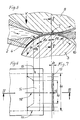
- a first heat sink 3 designed as a cooling roller and a second heat sink 8 designed as a cooling roller form an adjustable passage gap 7, which determines the thickness of the strip to be cast.
- a feed element 2 for molten metal 1, also called “pouring spout”, is assigned to the first cooling roller 3.
- the pouring opening 4 facing the jacket of the cooling roller 3 essentially has a U-profile. For this reason, the solidification begins at the edges of the strip to be cast earlier than in the strip center area, so that a partially solidified strip 5 with a channel-shaped profile is formed. The metal remains molten in the gutter.
- the molten metal comes into contact with the second cooling roller 8, it solidifies into a skin.
- the resulting skin and the partially rigid band 5 with its channel-shaped profile are joined to the desired band thickness, so that the band leaves the passage gap with its final dimensions.
- the strip 9 is detached from the first cooling roller 3 by means of a wedge 10. It is kept in contact with the second cooling roller 8 until it has solidified.
- the solidification front has advanced so far on the outer edge regions of the partially solidified belt 5 that when contact with the second cooling roller 8 no new skin needs to be formed in these areas, but on the Solidification front in these areas, doughy material only needs to be cooled further. It is important that these areas at the narrowest point of the passage gap 7 are still sufficiently soft to be able to be reduced to the desired strip thickness so that the calibrated or solidified strip leaving the passage gap has the desired dimensions of the finished strip.
- the strip thicknesses of the partially solidified strip required in the individual areas can be determined according to the solidification law known in continuous metal casting. Thereafter, the respective strip thicknesses d 1, d 2 (see FIGS.
- FIGS. 8 and 9 differs from that of FIG. 1 essentially in the design of the pouring spout 17, which is designed here as a channel which is open at the top.
- the level 18 of the molten metal should not fall below the level of the lower edge 19 of the heat sink 8 in the passage gap 19.
- this version there is no contact length mentioned above. In this case, the contact and thus also solidification lengths l 1 and l 2 extend into the passage gap.
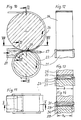
- the exemplary embodiment in FIGS. 10 to 13 differs from the previous exemplary embodiments in the pouring spout 20 and the first cooling roller 21.
- the cooling roller 21 has two cooled bandwidth limitation flanges 22 which prevent the molten metal from flowing out of the pouring spout 20 sideways.
- the pouring spout 20 has a rectangular pouring opening with a contact length l and a contact width b.
- the molten metal solidifies in the entire region of the pouring opening on all cast-on surfaces of the cooling roller 21, that is to say not only on the jacket but also on the jacket lateral limiting flanges 22. This creates a partially rigid band 23 with a trough-shaped cross section.
- the groove of the partially solidified band 23 is filled with molten metal. Laterally pulled down edges of the upper part of the pouring spout 20 extending into the pouring gap 25 together with the limiting flanges 22 ensure that no molten metal can flow off laterally.
- a skin is formed on the second cooling roller 26, which is formed when it is created in the passage gap 25 with the partially rigid band 22.
- the strip 24 is released from the cooling roller 21 by means of a release wedge 27 and is held in contact with the second cooling roller 27 until it has completely solidified.
- the exemplary embodiment in FIG. 14 is modified compared to the exemplary embodiment in FIGS. 10 to 13 in that the more intensive cooling of the band edges is brought about by two laterally arranged cooling zones 30. These cooling zones 30 dissipate the heat better than the central region 28 of the heat sink.
- the pouring spout 31, which is elongated in the upper region in the direction of the passage gap, has pulled-down edges which, together with the solidified side flanks of the partially solidified band 29, prevent the molten metal from flowing off laterally.
- the following exemplary embodiments differ from the previously discussed exemplary embodiments primarily in that they are set up in such a way that molten metal is simultaneously poured onto both cooling bodies designed as cooling rollers.
- the pouring opening 35 of the pouring spout 32 is designed in such a way that a partially rigid belt 36 with a channel-shaped profile is formed on the lower cooling roller 33 and a band 37 with a rectangular cross section is formed on the upper cooling roller 34.
- the solidification front has advanced so far that the two bands 36, 37 are joined together at the edge regions while reducing the overall thickness.
- the strip is given its final shape here.
- the strip 39 obtained in this way, with a still molten or doughy core 40, is also detached from the cooling roller 33 by a detaching wedge 41 and, with continued contact with the second cooling roller 34, until it has completely solidified chilled.
- the belt 39 already has a shell of high rigidity on all sides after leaving the passage gap 38, it is also possible not to cool the belt on the cooling roller 34 until it has completely solidified, but to continue straight ahead and to cool it with other coolants. In any case, this is easily possible if the tape is not too wide. However, further cooling on the cooling roller 34 is preferred.
- FIG. 18 shows a band in the passage gap, in which webs are formed between the side flanks and divide the channel that extends over the entire width of the band into a plurality of individual channels with molten metal 43 located therein.
- the partially rigid band 42 with the many small channels can be formed in that not only at the edge areas, but also at the various areas in between, the contact length on the cooling roller 33 is greater than in the areas where the Gutters are to be formed. Because of the large number of channels, such a belt has a high level of dimensional stability when it leaves the passage gap 33, so that further cooling until the belt has completely solidified is completely uncritical.
- the formation of the outlet opening 4 of the pouring spout 2 in the exemplary embodiment in FIG. 1 allows a partially rigid band 59 according to FIG. 21 with a plurality of small parallel channels 60, even when the molten metal is poured onto a first heat sink 3 instead of a tape with only one gutter, as shown in Figure 2.
- molten metal is poured onto both heat sinks 45, 46, 47 via a pouring spout 44.
- the second heat sink is formed by a belt 46 which is guided over two rollers 47 and which keeps the belt 49 calibrated in the passage gap 48 in contact with the first cooling roller 45 until it has completely solidified.
- the exemplary embodiment in FIG. 20 represents a modification of the exemplary embodiment in FIG. 1, since the molten metal is brought onto a first heat sink 51, 53 via a pouring spout 50.
- a second heat sink 52, 54 is only used after the formation of a partially rigid band with a trough-shaped profile.
- the heat sinks consist of cooling belts 51, 52 which run over cooling wheels 53, 54, 55.
- the cooling wheels 53, 54 with the cooling belts 51, 52 guided above them determine the thickness in the passage gap 57.
- the cooling belts 51, 52 are guided in parallel on support cushions 56. These support the band 58 coming out of the passage gap 57 and are kept in close contact with this band 58 for the purpose of intensive cooling.
- FIGS. 19, 20 are not limited to one form of pouring, be it only to a first heat sink or simultaneously to both heat sinks. Whether pouring on one or both sides is dependent on the choice of the pouring spout.
- the exemplary embodiment of FIG. 22 differs from that of FIGS. 15, 16, 18 above all in that not only the lower cooling roller 62, but also the upper cooling roller 63 are different over the bandwidth due to the corresponding design of the outlet opening 64 of the pouring spout 61 Contact lengths exist for the molten metal.
- the edges 65 of the pouring opening 64 of the pouring spout 61 facing the cooling rollers 62, 63 have a comb-like course. This creates a partially rigid belt 67 on the lower and upper cooling rollers 62, 63 with a plurality of small channels running in the belt running direction.
- the partially solidified strips are joined to form the strip 70, the molten metal remaining in the grooves 68 solidifying when the strip 70 is preferably in contact with a cooling roller 63 or 63.
- FIGS. 25 to 27 is modified compared to that of FIGS. 22 to 24 in that the cooling rollers 73, 74 are arranged horizontally next to one another with their axes, so that the molten metal is introduced above the passage gap 77 between the two cooling rollers 73, 74 .
- the molten metal 75 e.g. distributed by the described spout of the embodiment of Figures 22, 23.
- other melt distributors can also be used here, as in the previous exemplary embodiments. It is important that there are different contact lengths across the width of the tape in the tape running direction.
- line 72 shows the contact limit or start of contact of the molten metal with the cooling rollers 73, 74.
- the partially solidified tapes with the many parallel small channels of the exemplary embodiment in FIGS. 25 to 27, but also the corresponding tapes of the other exemplary embodiments, are so greatly reduced in thickness when passing through the passage gap 77 in the area of the solidified webs that the deformation caused by the reduced thickness transversely to partially solidified tape which is significantly counteracted in the solidification and cooling process, at least in the passage gap, impeded transverse shrinkage of the tape.
- the partially solidified tapes 76 are deformed when they are joined in the passage gap 77 at the contact points 78 to a length .DELTA.l and a width .DELTA.b, the length .DELTA.l preferably being chosen to be greater than the width .DELTA.b Material shift mainly in the direction of the bandwidth, as indicated by arrows 79 in FIGS. 26 and 27. The spread achieved in this way counteracts, as mentioned, at least the width shrinkage of the strip, which is impeded in the joining area, during solidification and cooling.
- the longitudinal deformation of the strip in the direction of arrow 80 when the partially solidified strips are joined in the passage gap is kept small in comparison to the achievable width, so that the solidification process is not disturbed when the strip is formed.
- a slight longitudinal deformation is not critical because it counteracts a longitudinal shrinkage of the band in the passage gap.
- the calibration of the strip thickness in the passage gap is based on the fact that before the partially solidified strips enter the passage gap, the total thickness of the solidified material is greater than the thickness of the calibrated strip leaving the passage gap, so that a deformation process takes place when the partially solidified strips pass through the gap .
- the required greater thickness of the partially solidified strips can be adjusted by adjusting the casting speed and / or the contact length of the molten metal with the heat sinks. It should be chosen in such a way that calibration to a constant strip thickness is ensured and, on the other hand, it is so small that there is at least no significant strip elongation when deforming.
- the complete solidification of a strip 70.75 according to Figure 24.27 with appropriate adjustment of the casting speed and / or the contact lengths l1, l2 with the heat sinks 62.63 and 73.74 can be set in this way be that the solidification of the molten cores 68 has already ended in the joining area ⁇ 1 according to FIG. 25 until it passes through the narrowest point between the heat sinks.
- the exemplary embodiment in FIGS. 28 to 30 differs from all the previous exemplary embodiments in that a hollow band is produced here.
- the cooling rollers 86 are also arranged horizontally next to one another with their axes.
- the molten metal is introduced into the passage gap 87 from below.
- the molten metal 81 stored in a melt container 83 is conveyed to a pouring spout 85 by means of a riser pipe 84 under the action of a pressure cushion 42 prevailing in the melt container 83.
- the pouring spout 85 is designed in the manner described, so that on the two cooling rollers 86 partially rigid bands 89, 90 are formed, each with a single channel or with several small channels. These partially rigid strips 89, 90 are joined together in the passage gap 87.
- the molten metal located in the chamber or chambers formed by the channels must be kept at a level in the band 88 at which no complete solidification has yet taken place. Only then can the chambers empty when the belt 88 is transported further.
Landscapes
- Engineering & Computer Science (AREA)
- Mechanical Engineering (AREA)
- Continuous Casting (AREA)
Abstract
Claims (17)
- Procédé pour la coulée continue de feuillards métalliques minces (9, 39), en particulier de feuillards d'acier avec une section transversale rectangulaire, dans lequel le métal en fusion est coulé sur au moins l'un de deux corps de refroidissement (3, 33, 8, 34) déplacés en direction du déplacement du feuillard formant entre eux une fente de passage réglable selon l'épaisseur de feuillard souhaitée, caractérisé par la combinaison des étapes de procédé suivantes:1. un feuillard partiellement solidifié (5, 36) avec un profil de solidification en forme de chenal est formé sur le premier corps de refroidissement (3, 33), dont le noyau (40) encore en fusion ou pâteux se trouve sur la face écartée du corps de refroidissement (3, 33).2. la formation d'une peau (37) enfermant le feuillard partiellement solidifié (5, 36) sur son côté par le noyau (40), en fusion ou pâteux se produit sur le second corps de refroidissement (8, 34), la peau (37) et le feuillard partiellement solidifié (5, 36) étant réunis en déformant les flancs latéraux solidifiés jusqu'à l'épaisseur de feuillard souhaitée.3. le refroidissement poursuivi du feuillard (9, 39) enfermé de tous les côtés avec un noyau en fusion ou pâteux se produit jusqu'à la solidification complète sur le second corps de refroidissement (8, 34).
- Procédé selon la revendication 1,
caractérisé en ce que la formation de la peau (37) a lieu sur le second corps de refroidissement (8, 34) par coulée du métal en fusion sur le second corps de refroidissement (8, 34) simultanément à la coulée du métal, en fusion sur le premier corps de refroidissement (3, 33). - Procédé pour la coulée continue de feuillards métalliques minces (9, 39), en particulier de feuillards d'acier avec une section transversale rectangulaire, dans lequel le métal en fusion est coulé sur au moins l'un de deux corps de refroidissement (3, 8) déplacés en direction du déplacement du feuillard formant entre eux une fente de passage réglable selon l'épaisseur de feuillard souhaitée,
caractérisé par la combinaison des étapes de procédé suivantes:1. un feuillard partiellement solidifié (5, 36) avec un profil de solidification en forme de chenal est formé sur le premier corps de refroidissement (3, 33), dont le noyau (40) encore en fusion ou pâteux se trouve sur la face écartée du corps de refroidissement (3, 33).2. la formation d'une peau (37) enfermant le feuillard partiellement solidifié (5, 36) sur son côté par le noyau (40), en fusion ou pâteux se produit sur le second corps de refroidissement (8, 34), par coulée du métal en fusion sur le second corps de refroidissement (8, 34) simultanément à la coulée du métal, en fusion sur le premier corps de refroidissement (3, 33), la peau (37) et le feuillard partiellement solidifié (5, 36) étant réunis en déformant les flancs latéraux solidifiés jusqu'à l'épaisseur de feuillard souhaitée. - Procédé selon la revendication 3,
caractérisé en ce que le refroidissement poursuivi du feuillard enfermé de tous les côtés avec un noyau en fusion ou pâteux se produit pour la solidification complète sur le second corps de refroidissement (8). - Procédé selon l'une des revendications 2 à 4,
caractérisé en ce que la formation de la seconde peau a lieu sous forme d'un feuillard partiellement solidifié (89, 90) avec un profil de solidification en forme de chenal dont le noyau en fusion ou pâteux est tourné vers le noyau en fusion ou pâteux du feuillard formé sur le premier corps de refroidissement. - Procédé selon l'une des revendications 1 à 5,
caractérisé en ce que le feuillard partiellement solidifié (90) reçoit sur le premier corps de refroidissement et le cas échéant sur le second corps de refroidissement (86), entre les flancs latéraux limitant les chenaux, des nervures. - Procédé selon l'une des revendications 1 à 6,
caractérisé en ce que la formation des flancs latéraux limitant le chenal du feuillard partiellement solidifié (5, 36, 89, 90) et le cas échéant des nervures se trouvant entre eux est effectuée par un refroidissement localement plus intensif ou mis en oeuvre plus tôt du métal en fusion dans les zones prévues pour ces flancs latéraux et nervures par rapport aux autres zones. - Procédé selon l'une des revendications 1 à 7,
caractérisé en ce que le métal en fusion (81) est coulé par en-dessous sur les corps de refroidissement (86) et le métal en fusion est maintenu en aval de la fente de passage au-dessous de la zone du feuillard complètement solidifié. - Procédé selon l'une des revendications 1 à 8,
caractérisé en ce que le ou les feuillards partiellement solidifiés (5, 36, 89, 90) sont réduits d'épaisseur dans la fente de passage de telle manière que la contraction transversale se produisant lors de la phase de solidification et de refroidissement soit au moins partiellement compensée. - Dispositif de coulée pour des feuillards métalliques (21, 26) avec deux corps de refroidissement (3, 33, 8, 34) mobiles en direction de déplacement du feuillard qui forment entre eux une fente de passage réglable et avec un élément d'amenée (2, 17, 20) pour le métal en fusion arrivant jusqu'à la fente de passage,
caractérisé par la combinaison des caractéristiques suivantes:1. au moins l'un des deux corps de refroidissement (21) et/ou l'élément d'amenée (17) est équipé pour un refroidissement plus intensif ou se produisant plus tôt du métal en fusion sur les bords du feuillard que dans la zone de milieu du feuillard.2. le second corps de refroidissement (8, 26, 34) est disposé à une distance du premier corps de refroidissement (3, 21, 33) telle que les feuillards formés sur les deux corps de refroidissement (3, 33, 8, 21, 26, 34) sont réunis sur les bords latéraux par leurs fronts de solidification pour former un feuillard (9, 24) ayant une coquille solidifiée de tous les côtés.3. le second corps de refroidissement (8, 26, 34) est équipé en tant que dispositif de post-refroidissement du feuillard partiellement solidifié (9, 24) jusqu'à sa solidification complète totale. - Dispositif de coulée pour des feuillards métalliques avec deux corps de refroidissement (3, 33, 8, 21, 26; 34) mobiles en direction de déplacement du feuillard qui forment entre eux une fente de passage réglable et avec un élément d'amenée (17, 20) pour le métal en fusion arrivant jusqu'à la fente de passage,
caractérisé par la combinaison des caractéristiques suivantes:1. au moins l'un des deux corps de refroidissement (21) et/ou l'élément d'amenée (17) est équipé pour un refroidissement plus intensif ou se produisant plus tôt du métal en fusion sur les bords du feuillard que dans la zone de milieu du feuillard.2. Le second corps de refroidissement (8, 26) et l'élément d'amenée (17, 20) sont équipés pour une coulée simultanée du métal en fusion sur les deux corps de refroidissement (3, 8, 21, 26).3. Le second corps de refroidissement (8, 26) est disposé à une distance du premier corps de refroidissement (3, 21) telle que les feuillards formés sur les deux corps de refroidissement (3, 8, 21, 26) sont réunis sur les bords par leurs fronts de solidification pour former un feuillard (24) ayant une coquille solidifiée de tous les côtés. - Dispositif de coulée selon la revendication 11,
caractérisé en ce que le second corps de refroidissement (8, 26) est équipé en tant que dispositif de post-refroidissement du feuillard partiellement solidifié jusqu'à sa solidification complète totale. - Dispositif de coulée selon l'une des revendications 10 à 12,
caractérisé en ce que la distance entre les corps de refroidissement (3, 8, 21, 26) dans la fente de passage est inférieure à la hauteur du front de solidification aux bords du ou des feuillards partiellement solidifiés (5, 36). - Dispositif de coulée selon l'une des revendications 10 à 13,
caractérisé en ce que l'ouverture de coulée (4) est réalisée sur son côté tourné vers le corps de refroidissement (3) en forme de U ou en forme de peigne, les pointes du profil en U ou en peigné étant dirigées en direction inverse de la direction de déplacement du corps de refroidissement (3). - Dispositif de coulée selon l'une des revendications 10 à 13,
caractérisé en ce que l'élément d'amenée (20) a une ouverture de coulée rectangulaire et le corps de refroidissement (21) présente des zones de refroidissement (22, 30) adjointes aux bords du feuillard qui ont une conductibilité thermique plus élevée que les zones (28) qui se trouvent entre elles. - Dispositif de coulée selon l'une des revendications 10 à 15,
caractérisé en ce que, avec une fente de passage sensiblement horizontale, l'élément d'amenée est un chenal ouvert au-dessus. - Dispositif de coulée selon l'une des revendications 10 à 15,
caractérisé en ce que, avec une fente de passage sensiblement verticale, l'élément d'amenée (85) est disposé sur les corps de refroidissement (86) à la face inférieure.
Priority Applications (1)
| Application Number | Priority Date | Filing Date | Title |
|---|---|---|---|
| AT89908695T ATE83408T1 (de) | 1988-07-05 | 1989-07-05 | Verfahren und vorrichtung zum kontinuierlichen giessen von metallbaendern. |
Applications Claiming Priority (2)
| Application Number | Priority Date | Filing Date | Title |
|---|---|---|---|
| DE3822656A DE3822656A1 (de) | 1988-07-05 | 1988-07-05 | Verfahren zum kontinuierlichen giessen von metallbaendern und vorrichtung zur durchfuehrung des verfahrens |
| DE3822656 | 1988-07-05 |
Publications (2)
| Publication Number | Publication Date |
|---|---|
| EP0423233A1 EP0423233A1 (fr) | 1991-04-24 |
| EP0423233B1 true EP0423233B1 (fr) | 1992-12-16 |
Family
ID=6357955
Family Applications (1)
| Application Number | Title | Priority Date | Filing Date |
|---|---|---|---|
| EP89908695A Expired - Lifetime EP0423233B1 (fr) | 1988-07-05 | 1989-07-05 | Procede et dispositif de coulee en continu de bandes metalliques |
Country Status (3)
| Country | Link |
|---|---|
| EP (1) | EP0423233B1 (fr) |
| DE (2) | DE3822656A1 (fr) |
| WO (1) | WO1990000453A1 (fr) |
Families Citing this family (1)
| Publication number | Priority date | Publication date | Assignee | Title |
|---|---|---|---|---|
| RU2111829C1 (ru) * | 1996-10-09 | 1998-05-27 | Буркин Сергей Павлович | Способ непрерывного получения тонкой металлической полосы и машина для его осуществления |
Family Cites Families (8)
| Publication number | Priority date | Publication date | Assignee | Title |
|---|---|---|---|---|
| US2171132A (en) * | 1937-06-19 | 1939-08-29 | Simons Aaron | Method of forming elements from molten metal |
| US2978761A (en) * | 1957-05-03 | 1961-04-11 | Kaiser Aluminium Chem Corp | Continuous casting apparatus |
| CA964033A (en) * | 1971-02-26 | 1975-03-11 | Jones And Laughlin Steel Corporation | Direct casting of channel-shaped strip |
| JPS5938062B2 (ja) * | 1978-03-15 | 1984-09-13 | 日本碍子株式会社 | 金属の連続鋳造法 |
| CH666842A5 (de) * | 1984-03-01 | 1988-08-31 | Concast Service Union Ag | Verfahren und vorrichtung zum kontinuierlichen giessen von metallen in form von band zwischen zwei gekuehlten achsparallelen trommeln. |
| YU44261B (en) * | 1985-06-11 | 1990-04-30 | Unial Boris Kidric | Dye for tape tuft casting with casting wheel and traveling tape |
| JPS6238745A (ja) * | 1985-08-13 | 1987-02-19 | Nippon Yakin Kogyo Co Ltd | 金属薄板の直接製造装置 |
| JPH01118346A (ja) * | 1987-10-29 | 1989-05-10 | Sumitomo Heavy Ind Ltd | ツインベルトキャスターによる鋳造方法およびその装置 |
-
1988
- 1988-07-05 DE DE3822656A patent/DE3822656A1/de not_active Withdrawn
-
1989
- 1989-07-05 EP EP89908695A patent/EP0423233B1/fr not_active Expired - Lifetime
- 1989-07-05 WO PCT/EP1989/000769 patent/WO1990000453A1/fr not_active Ceased
- 1989-07-05 DE DE8989908695T patent/DE58903053D1/de not_active Expired - Fee Related
Also Published As
| Publication number | Publication date |
|---|---|
| EP0423233A1 (fr) | 1991-04-24 |
| WO1990000453A1 (fr) | 1990-01-25 |
| DE58903053D1 (de) | 1993-01-28 |
| DE3822656A1 (de) | 1990-01-11 |
Similar Documents
| Publication | Publication Date | Title |
|---|---|---|
| EP2627464B1 (fr) | Procédé et installation de production à efficacité énergétique pour une bande d'acier laminée à chaud | |
| DE3627991C2 (fr) | ||
| AT401744B (de) | Verfahren und anlage zum stranggiessen | |
| EP1478479B1 (fr) | Procede de coulee continue et de faconnage direct d'un metal, notamment d'une barre de coulee en materiaux a base d'acier | |
| EP0834364B1 (fr) | Méthode et dispositif pour des machines de coulée continue à haute vitesse avec réduction d'épaisseur pendant la solidification | |
| EP3495086B1 (fr) | Procédé et dispositif de fabrication d'un matériau composite en forme de bande | |
| DE3783187T2 (de) | Kuehlrollen zum giessen von schnell erstarrenden metallblechen. | |
| EP0233147A1 (fr) | Procédé et dispositif de coulée continue entre rouleaux | |
| EP1109638A1 (fr) | Procede de production de bandes d'acier de charge optimisee | |
| DE2548939C2 (de) | Verfahren und Vorrichtung zum Stranggießen von Bändern | |
| DD293283A5 (de) | Verfahren und vorrichtung zum stranggiessen duenner metallischer gegenstaende mit dickenverringerung unterhalb der kokille | |
| EP0423233B1 (fr) | Procede et dispositif de coulee en continu de bandes metalliques | |
| EP0558739B1 (fr) | Procede et dispositif pour la preparation de couches minces de liquide sous forme de revetement ou de pellicule | |
| EP0208890B1 (fr) | Procédé de coulée continue d'un lingot métallique, en particulier d'une bande ou d'un profil, et installation pour réaliser ce procédé | |
| DE19638906C1 (de) | Verfahren und Vorrichtung zur Erzeugung von beschichteten Strängen aus Metall, insbesondere von Bändern aus Stahl | |
| DE3521778C2 (fr) | ||
| DE10057876C1 (de) | Verfahren und Vorrichtung zur Herstellung von Warmband in einer Minihütte | |
| DE19746876C2 (de) | Verfahren und Vorrichtung zur Erzeugung von schmalem Warmband unterschiedlicher Breiten aus Dünnbrammen | |
| DE3302333C2 (fr) | ||
| AT397478B (de) | Verfahren und vorrichtung zum stranggiessen eines dünnen bandes oder einer dünnen bramme | |
| EP1827735B1 (fr) | Procede et dispositif de coulee en bande de metaux | |
| DE60204868T2 (de) | Vorrichtung zum einführen von stahlschmelze von einem behälter in einen kristallisator mit rollen | |
| DE2842094C3 (de) | Bewegliche Stranggießkokille für dehnungsempfindliche Metalle, insbesondere Stahl | |
| DE10114269C1 (de) | Verfahren und Vorrichtung zur Herstellung von Warmband mittels Zweirollen-Dünnbandgießanlagen | |
| EP1412110A1 (fr) | Procede de coulee continue verticale d'un feuillard d'acier |
Legal Events
| Date | Code | Title | Description |
|---|---|---|---|
| PUAI | Public reference made under article 153(3) epc to a published international application that has entered the european phase |
Free format text: ORIGINAL CODE: 0009012 |
|
| 17P | Request for examination filed |
Effective date: 19901222 |
|
| AK | Designated contracting states |
Kind code of ref document: A1 Designated state(s): AT DE FR GB IT SE |
|
| 17Q | First examination report despatched |
Effective date: 19920331 |
|
| GRAA | (expected) grant |
Free format text: ORIGINAL CODE: 0009210 |
|
| AK | Designated contracting states |
Kind code of ref document: B1 Designated state(s): AT DE FR GB IT SE |
|
| REF | Corresponds to: |
Ref document number: 83408 Country of ref document: AT Date of ref document: 19930115 Kind code of ref document: T |
|
| ET | Fr: translation filed | ||
| REF | Corresponds to: |
Ref document number: 58903053 Country of ref document: DE Date of ref document: 19930128 |
|
| RAP2 | Party data changed (patent owner data changed or rights of a patent transferred) |
Owner name: SUNDWIGER EISENHUETTE MASCHINENFABRIK GMBH & CO. |
|
| GBT | Gb: translation of ep patent filed (gb section 77(6)(a)/1977) |
Effective date: 19930122 |
|
| ITF | It: translation for a ep patent filed | ||
| PGFP | Annual fee paid to national office [announced via postgrant information from national office to epo] |
Ref country code: FR Payment date: 19930628 Year of fee payment: 5 |
|
| PGFP | Annual fee paid to national office [announced via postgrant information from national office to epo] |
Ref country code: SE Payment date: 19930705 Year of fee payment: 5 Ref country code: GB Payment date: 19930705 Year of fee payment: 5 |
|
| PGFP | Annual fee paid to national office [announced via postgrant information from national office to epo] |
Ref country code: AT Payment date: 19930706 Year of fee payment: 5 |
|
| PGFP | Annual fee paid to national office [announced via postgrant information from national office to epo] |
Ref country code: DE Payment date: 19930827 Year of fee payment: 5 |
|
| PLBE | No opposition filed within time limit |
Free format text: ORIGINAL CODE: 0009261 |
|
| STAA | Information on the status of an ep patent application or granted ep patent |
Free format text: STATUS: NO OPPOSITION FILED WITHIN TIME LIMIT |
|
| 26N | No opposition filed | ||
| PG25 | Lapsed in a contracting state [announced via postgrant information from national office to epo] |
Ref country code: GB Effective date: 19940705 Ref country code: AT Effective date: 19940705 |
|
| PG25 | Lapsed in a contracting state [announced via postgrant information from national office to epo] |
Ref country code: SE Effective date: 19940706 |
|
| EUG | Se: european patent has lapsed |
Ref document number: 89908695.3 Effective date: 19950210 |
|
| GBPC | Gb: european patent ceased through non-payment of renewal fee |
Effective date: 19940705 |
|
| PG25 | Lapsed in a contracting state [announced via postgrant information from national office to epo] |
Ref country code: FR Effective date: 19950331 |
|
| PG25 | Lapsed in a contracting state [announced via postgrant information from national office to epo] |
Ref country code: DE Effective date: 19950401 |
|
| EUG | Se: european patent has lapsed |
Ref document number: 89908695.3 |
|
| REG | Reference to a national code |
Ref country code: FR Ref legal event code: ST |
|
| PG25 | Lapsed in a contracting state [announced via postgrant information from national office to epo] |
Ref country code: IT Free format text: LAPSE BECAUSE OF NON-PAYMENT OF DUE FEES;WARNING: LAPSES OF ITALIAN PATENTS WITH EFFECTIVE DATE BEFORE 2007 MAY HAVE OCCURRED AT ANY TIME BEFORE 2007. THE CORRECT EFFECTIVE DATE MAY BE DIFFERENT FROM THE ONE RECORDED. Effective date: 20050705 |