EP0423424A2 - Bomblet-Trägergeschoss mit lagenweise angeordneten Leicht-Übungsbomblets - Google Patents
Bomblet-Trägergeschoss mit lagenweise angeordneten Leicht-Übungsbomblets Download PDFInfo
- Publication number
- EP0423424A2 EP0423424A2 EP19900109953 EP90109953A EP0423424A2 EP 0423424 A2 EP0423424 A2 EP 0423424A2 EP 19900109953 EP19900109953 EP 19900109953 EP 90109953 A EP90109953 A EP 90109953A EP 0423424 A2 EP0423424 A2 EP 0423424A2
- Authority
- EP
- European Patent Office
- Prior art keywords
- bomblet
- bomblets
- housing
- exercise
- projectile according
- Prior art date
- Legal status (The legal status is an assumption and is not a legal conclusion. Google has not performed a legal analysis and makes no representation as to the accuracy of the status listed.)
- Granted
Links
- 239000004033 plastic Substances 0.000 claims abstract description 20
- 230000001133 acceleration Effects 0.000 claims abstract description 8
- 239000000123 paper Substances 0.000 claims description 6
- 125000006850 spacer group Chemical group 0.000 claims description 5
- 239000000853 adhesive Substances 0.000 claims description 3
- 230000001070 adhesive effect Effects 0.000 claims description 3
- YZCKVEUIGOORGS-OUBTZVSYSA-N Deuterium Chemical compound [2H] YZCKVEUIGOORGS-OUBTZVSYSA-N 0.000 claims description 2
- 239000004952 Polyamide Substances 0.000 claims description 2
- 229910052805 deuterium Inorganic materials 0.000 claims description 2
- 229920002647 polyamide Polymers 0.000 claims description 2
- 238000005474 detonation Methods 0.000 abstract description 3
- 239000012634 fragment Substances 0.000 abstract description 2
- 239000004576 sand Substances 0.000 abstract description 2
- XLYOFNOQVPJJNP-UHFFFAOYSA-N water Substances O XLYOFNOQVPJJNP-UHFFFAOYSA-N 0.000 abstract description 2
- 230000008447 perception Effects 0.000 abstract 1
- 238000009434 installation Methods 0.000 description 3
- 239000000463 material Substances 0.000 description 3
- 229910052751 metal Inorganic materials 0.000 description 3
- 239000002184 metal Substances 0.000 description 3
- 238000000034 method Methods 0.000 description 3
- 239000000945 filler Substances 0.000 description 2
- 235000013351 cheese Nutrition 0.000 description 1
- 230000000694 effects Effects 0.000 description 1
- 230000005484 gravity Effects 0.000 description 1
- 229910001385 heavy metal Inorganic materials 0.000 description 1
- 238000012423 maintenance Methods 0.000 description 1
- 238000004519 manufacturing process Methods 0.000 description 1
- 239000002362 mulch Substances 0.000 description 1
- 230000035515 penetration Effects 0.000 description 1
- 230000001105 regulatory effect Effects 0.000 description 1
- 230000006641 stabilisation Effects 0.000 description 1
- 238000011105 stabilization Methods 0.000 description 1
Images
Classifications
-
- F—MECHANICAL ENGINEERING; LIGHTING; HEATING; WEAPONS; BLASTING
- F42—AMMUNITION; BLASTING
- F42B—EXPLOSIVE CHARGES, e.g. FOR BLASTING, FIREWORKS, AMMUNITION
- F42B8/00—Practice or training ammunition
- F42B8/12—Projectiles or missiles
- F42B8/22—Fall bombs
-
- F—MECHANICAL ENGINEERING; LIGHTING; HEATING; WEAPONS; BLASTING
- F42—AMMUNITION; BLASTING
- F42B—EXPLOSIVE CHARGES, e.g. FOR BLASTING, FIREWORKS, AMMUNITION
- F42B12/00—Projectiles, missiles or mines characterised by the warhead, the intended effect, or the material
- F42B12/02—Projectiles, missiles or mines characterised by the warhead, the intended effect, or the material characterised by the warhead or the intended effect
- F42B12/36—Projectiles, missiles or mines characterised by the warhead, the intended effect, or the material characterised by the warhead or the intended effect for dispensing materials; for producing chemical or physical reaction; for signalling ; for transmitting information
- F42B12/56—Projectiles, missiles or mines characterised by the warhead, the intended effect, or the material characterised by the warhead or the intended effect for dispensing materials; for producing chemical or physical reaction; for signalling ; for transmitting information for dispensing discrete solid bodies
- F42B12/58—Cluster or cargo ammunition, i.e. projectiles containing one or more submissiles
- F42B12/62—Cluster or cargo ammunition, i.e. projectiles containing one or more submissiles the submissiles being ejected parallel to the longitudinal axis of the projectile
Definitions
- the invention relates to a bomblet carrier projectile with practice bomblets arranged in the projectile shell according to the features specified in the preamble of claim 1.
- a desired ground signature which is to appear in a similar manner to a sharp bomblet during the impact as a detonation cloud with a flash of light and a bang, is no longer perceptible when using pyrotechnic lighting.
- the object of the invention is to design the bomblet carrier projectile and exercise bomblets to be transported therefrom in such a way that the exercise bomblet on the one hand withstands the high acceleration forces which occur during transport to the target area and on the other hand does not sink into it when it hits a resilient surface.
- a very light exercise bomblet is created, whereby the total weight of the exercise bomblet is reduced in such a way that deep penetration into a flexible surface is avoided and the signature with detonation cloud, flash of light and bang is good is noticeable.
- This paper and / or plastic-based practice bomblet housing also offers, in a particularly advantageous manner, absolute security against splintering, because compared to a practice bomblet housing made of, for example, die-cast, there can be no danger of flying fragments.
- a paper-based practice bomblet housing if there is a misfire compared to a metal housing, there are advantageously no residues because, for example, the practice bomblet housing rots early.
- bom-bomblet housing made on paper and / or plastic is subject to tighter limits than a metal case in terms of load-bearing capacity, for example in terms of pressure resistance
- support of the bom-bomblets according to the invention within the bomblet carrier floor allows the bom-bomblets to withstand the high initial accelerations Withstand transport to the target area and can be ejected over the target area in a manner known per se via an ejection charge from the rear of the carrier floor.
- a layer-by-layer support of the practice bomblets within the carrier storey has proven to be an advantageous solution, as a result of which the practice bomblets located in one plane or position are supported in the projectile-axial direction.
- the support elements consist of disc-shaped support plates arranged transversely to the projectile axis and of axial supports, as a result of which the exercise bomblets can be inserted and supported in layers in the bomblet carrier floor.
- the arrangement of the exercise bomblets in one layer is not fixed in the circumferential direction and can therefore vary from layer to layer. This results in a simplified installation method.
- the axial supports between the support plates ensure reliable maintenance of a support spacing in bomblet length so that the individual practice bomblets do not have to absorb additional axial forces from practice bomblets of pre-stacked layers.
- the axial forces resulting from this layer-by-layer stacking of bom bomblets arranged one above the other cannot therefore have a negative effect on the stability of the bomblet housing according to the invention, the load due to the initial acceleration being further advantageously reduced due to the reduced bomblet housing weight.
- the axial supports can be arranged adjacent to the shell of the storey, filling the spaces of the exercise bomblets as fillers in a space-saving manner or can be arranged between two adjacent support plates as a one-piece or multi-piece central support in the inner space formed by the exercise bomblets.
- This central support contains an axial gas passage channel for the ignition of all practice bomblets arranged in the carrier floor.
- each support plate contains connecting grooves on the top side from the central gas pressure channel to the individual exercise bomblets, as a result of which these can be ignited from below without additional means.
- the different axial supports also allow the installation of differently designed exercise bomblets.
- the arrangement of external axial supports allows the installation of additional practice bomblets with lateral ignition, for example via lateral bomblet housing bores or an ignition cord located on the periphery of the bomblet housing. Due to the low axial bomblet load, inexpensive and easily manufactured housing configurations are possible, which can consist, for example, of a simple cardboard tube with glued-in cardboard or plastic disks or a one-piece housing pot formed from cardboard.
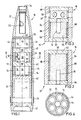
- FIG. 1 illustrates a bomblet carrier projectile 10, the housing 12 of which has a cylindrical area for receiving exercise bomblets 14, 16, 18, 20, 21 shown in more detail in FIGS. 2 to 11 and a front ogival projectile area 22 for receiving an igniter 24, one of a Ejection charge 26 and ejection plate 28 existing ejection unit.
- the ejection plate 28 contains a central gas passage 30 'through which the ejection charge 26 during the ejection process of the exercise bomblets over a target area in each bomblet 14, 16, 18, 20, 21 located ignition delay set 15, 74, 76 can be ignited.
- the exercise bomblets 14 received by the bomblet carrier projectile 10 in FIG. 1 are supported in layers within the bomblet carrier projectile 10, for which purpose stackable support elements 42, 44, 46 (FIG. 5) are arranged in the carrier projectile envelope 12 in the projectile axial direction.
- a support element is provided by an exercise bomb 14 located below each in the same flat position and disk-shaped support plate 42 arranged transversely to the projectile axis 11, which are supported to the adjacent support plates 42 by axial supports 44, the axial supports having a height corresponding to the bomblet length in order to form a sufficient support spacing.
- the axial supports 44 shown in FIG. 1 lie between two adjacent support plates 42 on the projectile shell 12 and are designed as fillers filling the spaces 48 (FIG. 6) between the exercise bomblets 14. These axial supports 44 can also be used in advantageous use of a different weight described in DE 36 29 668 C1 for regulating the center of gravity of the support projectile 10.
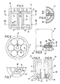
- the support plates 42 can, however, as shown in Figures 5 and 6, are supported by a centrally arranged axial support 46, which can be constructed in one or more pieces and on the inside forms a section of the central gas passage 30 'and on the outside radially to the respective bomblet circumference of each of the bomblets 14, 20, 21 located in a flat position rests. Due to the above-described external design of these axial supports 46, the advantage of a holder known from DE 38 08 898 A1 can be used for radial securing of the bomblets and for securing in the circumferential direction.
- This disk-shaped support plate 42 contains, on the side facing, for example, the exercise bomblet 14, grooves 50, 52 shown in more detail in FIG. 7 for the passage of the Gas pressure and the flame to ignite all practice bomblets arranged on the support plate 42.
- the gas initially flows from the axial gas passage 30 'via radially extending grooves 50 arranged in a star shape and from there via a circular groove 52 to each exercise bomb 14, whereby an ignition delay set 15, 74, arranged at the end in the exercise bombs 14, 20, 21 76 is ignitable.
- the exercise bomblets 14 fill a partial volume of the bomblet carrier floor 12 in a reduced number, the remaining partial volume being filled by a hollow cylinder 43 connected to the lowermost support plate 42.
- the bomblet carrier floor 10 is further provided with a guide belt 45 known per se and a floor 47 that can be released when the bomblets are ejected above the target area.
- the bomblet housings 32, 34, 36, 38, 40 shown in detail in FIGS. 2, 3 and 8 to 11 consist entirely or at least part of the housing of cardboard.
- This cardboard can have a weight between 50 to 950 g / m2 depending on the intended use as a casing tube 54, 56, 58 or as a cover 62, 64.
- the casing tube 54, 56, 58 can consist of wrapped paper and have a greater specific weight than the cover 62, 64.
- the strength of the practice bomblet housing 32, 34, 36, 38, 40 made of cardboard and / or plastic must be so high that the exercise bomblet 14, 16, 18, 20, 21 withstands the launch acceleration of the bomblet carrier projectile 10 .
- the cardboard or plastic housing material enables a specific weight of less than 1 kg / dm3 to be achieved for the entire practice bomblet unit, so that the practice bomblets are floatable.
- the bomblet housings 32, 34, 36 shown in FIGS. 2, 3, 8 and 9 contain a cardboard or plastic tube 54, 56, 58 as a jacket and a cardboard or plastic cover 62, 64 on the end face, which has a deuterium charge 60 on both inside the tube Support end faces.
- the spacing of the covers 62, 64 is advantageously determined by a spacer tube 68, which rests between the covers 62, 64 on the inside 66 of the bomblet housing 32, 34, 36, can be made of cardboard or plastic and with the tubular housing shell 54, 56, 58 is connected via an adhesive connection. Likewise, the covers 62, 64 are connected to the housing shell 54, 56, 58 of the practice bomblets via an adhesive connection.
- the practice bomb 14 shown in FIG. 2 contains a pyrotechnic detonator with ignition retardation set 15, which is fastened to the bottom cover 64 in a manner shown and protrudes into the Deutch 60, and can thus be easily traversed by the gas passage 30 and the grooves 50, 52 Ignite the flame of the ignition charge 26.
- ignition delay sets 15 are known and ignite the German charge 60 after a predetermined time after the practice bomblets hit the underground of the target area.
- Both covers 62, 64 form a closed cylindrical bomblet housing 14 with the casing tube 54.
- the casing tube 56 protrudes beyond the upper cover 64, the upper cover 64 carrying the ignition delay set 15 which protrudes downwards into the Deutch 60 and the casing pipe 56 has lateral bores 57 for igniting the ignition delay set 15 .
- a further cover 65 and a further spacer tube 68 can be connected on the inside to the casing tube 56 above the bores 57.
- the practice bomblet 18 shown in FIG. 8 can be ignited directly by the flame passing through the gas passage 30.
- the tubular jacket 58 of the practice bomblet housing 36 contains on the outside a circumferential groove 70 for receiving an ignition cord 72, from which an ignition delay set 74 projecting radially into the Deutch 60 can be ignited, the ignition delay set 74 being able to support the lower cover 62.
- bomblet housing 38, 40 which according to FIGS. 10 and 11 shows cup-shaped design variants.
- bomblet housings 38, 40 for example made of cardboard, can be produced by the mulch method, the tubular housing casing 59 (FIG. 10) either being comparatively thick-walled for stabilization or the casing 71 (FIG. 11) being reinforced with longitudinal ribs 73.
- the end 78 of the housing shell 59, 71 which initially protrudes downward in the axial direction, can be flanged in the radial direction in an uncomplicated manner.
- the material cardboard or plastic ensures further embodiments falling under the scope of protection Practice bomblet housing, which are not shown in the drawing and open up the possibility of arranging the practice bomblets in layers in a cheese corner shape.
Landscapes
- Engineering & Computer Science (AREA)
- General Engineering & Computer Science (AREA)
- Chemical & Material Sciences (AREA)
- Combustion & Propulsion (AREA)
- Filling Or Discharging Of Gas Storage Vessels (AREA)
- Aiming, Guidance, Guns With A Light Source, Armor, Camouflage, And Targets (AREA)
- Toys (AREA)
Abstract
Description
- Die Erfindung betrifft ein Bombletträgergeschoß mit in der Geschoßhülle angeordneten Übungsbomblets nach den im Oberbegriff des Patentanspruchs 1 angegebenen Merkmalen.
- Bei derartig aus der DE 38 09 177 C1 bekannten oder unter dem Aktenzeichen DE-P 38 41 649.2 vorgeschlagenen Bombletträgergeschossen enthalten davon in ein Zielgebiet zu transportierende und in einer vorgegebenen Höhe ausstoßbare Übungsbomblets ein Gehäuse aus Metall wodurch jedes Übungsbomblet in der Lage ist, innerhalb des Trägergeschosses die Beschleunigungskräfte von beispielsweise darübergestapelten Übungsbomblets aufzunehmen. Bei diesen Übungsbomblets wird es jedoch als nachteilig angesehen, daß sie beim Auftreffen auf einen nachgiebigen Untergrund wie Morast, Sumpf, Schnee, Sand oder Wasser aufgrund des schweren Metallgehäuses in diesen Untergrund eindringen und versinken können. Dadurch ist eine gewünschte Bodensignatur, die in ähnlicher Weise wie bei einem scharfen Bomblet während des Aufschlages als Detonationswolke mit Lichtblitz und Knall auftreten soll, bei Verwendung einer pyrotechnischen Anfeuerung nicht mehr wahrnehmbar.
- Aufgabe der Erfindung ist es, daß Bombletträgergeschoß und davon zu transportierende Übungsbomblets derartig auszubilden, daß das Übungsbomblet einerseits den beim Transport ins Zielgebiet auftretenden hohen Beschleunigungskräften standhält und andererseits beim Auftreffen auf einen nachgiebigen Untergrund nicht darin versinkt.
- Gelöst wird diese Aufgabe durch die im kennzeichnenden Teil des Patentanspruchs 1 genannten Merkmale.
- Vorteilhafte Ausgestaltungen der Erfindung gehen aus den Merkmalen der Unteransprüche hervor.
- Durch den erfindungsgemäßen Einsatz von einem auf Papier- und/oder Kunststoffbasis hergestellten Bombletgehäuse entsteht ein sehr leichtes Übungsbomblet, wodurch das Gesamtgewicht des Übungsbomblets derartig vermindert wird, daß ein tiefes Eindringen in einen nachgiebigen Untergrund vermieden wird und die Signatur mit Detonationswolke, Lichtblitz und Knall gut wahrnehmbar ist. Dieses auf Papier- und/oder Kunststoffbasis hergestellte Üb-Bombletgehäuse bietet darüber hinaus besonders vorteilhaft eine absolute Splittersicherheit, weil gegenüber einem Üb-Bombletgehäuse aus beispielsweise Druckguß keine Gefahr durch wegfliegende Splitter entstehen kann. Bei einem auf Papierbasis hergestellten Üb-Bombletgehäuse verbleiben bei einer Fehlzündung gegenüber einem Metallgehäuse weiter vorteilhaft keine Rückstände, weil beispielsweise durch Feuchtigkeit bereits frühzeitig das Üb-Bombletgehäuse verrottet.
- Obwohl dem auf Papier- und/oder Kunststoffbasis hergestellten Üb-Bombletgehäuse gegenüber einem Metallgehäuse hinsichtlich der Belastbarkeit beispielsweise bezüglich der Druckfestigkeit engere Grenzen gesetzt sind, erlaubt dennoch eine erfindungsgemäße Abstützung der Üb-Bomblets innerhalb des Bombletträgergeschosses, daß die Üb-Bomblets den hohen Anfangsbeschleunigungen beim Transport ins Zielgebiet standhalten und über dem Zielgebiet in an sich bekannter Weise über eine Ausstoßladung aus dem Heck des Trägergeschosses ausgestoßen werden können.
- Als vorteilhafte Lösung hat sich eine lagenweise Abstützung der Üb-Bomblets innerhalb des Trägergeschosses herausgestellt, wodurch die in einer Ebene bzw. Lage befindlichen Üb-Bomblets in geschoßaxialer Richtung abgestützt werden.
- Die Stützelemente bestehen aus quer zur Geschoßachse angeordneten scheibenförmigen Stützplatten und aus Axialstützen, wodurch die Übungsbomblets lagenweise in das Bombletträgergeschoß eingeführt und abgestützt werden können. Die Anordnung der Übungsbomblets in einer Lage ist dabei in Umfangsrichtung nicht festgelegt, und kann deshalb von Lage zu Lage verschieden sein. Daraus resultiert eine vereinfachte Einbauweise.
- Die Axialstützen zwischen den Stützplatten gewährleisten eine sichere Einhaltung eines Stützabstandes in Bombletlänge, so daß die einzelnen Üb-Bomblets keine zusätzlichen Axialkräfte von Üb-Bomblets vorgestapelter Lagen aufnehmen müssen. Die aus dieser lagenweisen Stapelung übereinander angeordneter Üb-Bomblets resultierenden Axialkräfte können sich somit nicht negativ auf die Stabilität des erfindungsgemäßen Bombletgehäuses aufwirken, wobei die Belastung durch die Anfangsbeschleunigung aufgrund des reduzierten Bombletgehäusegewichtes in weiter vorteilhafter Weise noch reduziert wird.
- Die Axialstützen können in dem Trägergeschoß an der Geschoßhülle anliegend angeordnet sein, wobei sie raumsparend die Freiräume der Übungsbomblets als Füllstücke ausfüllen oder zwischen zwei benachbarten Stützplatten als ein- oder mehrstückige Zentralstütze in dem von den Üb-Bomblets gebildeten Innenfreiraum angeordnet sein können. Diese Zentralstütze enthält im Inneren einen axialen Gasdurchlaßkanal für die Anzündung aller im Trägergeschoß angeordneten Übungsbomblets.
- Nach einem weiteren Ausgestaltungsmerkmal enthält jede Stützplatte oberseitig Verbindungsnuten von dem zentralen Gasdruckkanal zu den einzelnen Übungsbomblets, wodurch diese ohne zusätzliche Mittel von unten angezündet werden können. Die unterschiedlichen Axialstützen ermöglichen auch den Einbau von unterschiedlich aufgebauten Übungsbomblets.
- So gestattet die Anordnung von äußeren Axialstützen den Einbau von weiteren Übungsbomblets mit seitlicher Anzündung, beispielsweise über seitliche Bombletgehäusebohrungen oder eine am Bombletgehäuseumfang befindliche Anzündschnur. Aufgrund der geringen axialen Bombletbelastung sind kostengünstig und einfach herstellbare Gehäusekonfigurationen möglich, welche beispielsweise aus einem einfachen Papprohr mit eingeklebten Papp- oder Kunststoffscheiben oder einem aus Pappe umgeformten einstückigen Gehäusetopf bestehen können.
- Die Erfindung wird anhand mehrerer in den Zeichnungen dargestellter Ausführungsbeispiele des näheren erläutert.
- Es zeigt:
- Figur 1 ein Bombletträgergeschoß mit darin lagenweise abgestützten Übungsbomblets in einem Längsschnitt,
- Figur 2 ein in der Figur eingesetztes Übungsbomblet in einem Längsschnitt,
- Figur 3 ein weiteres in der Figur 1 einsetzbares Übungsbomblet in einem Längsschnitt,
- Figur 4 einen in der Figur 1 mit IV-IV gekennzeichneten Querschnitt durch das Trägergeschoß,
- Figur 5 das Bombletträgergeschoß mit einer zentralen axialen Abstützung einer Bombletlage in einem ausschnittsweise dargestellten Längsschnitt,
- Figur 6 ein in der Figur 5 mit VI-VI gekennzeichneten Querschnitt,
- Figur 7 einen in der Figur 5 mit VII-VII gekennzeichneten Querschnitt,
- Figur 8 ein Übungsbomblet mit ringförmiger Anzündung in einer Seitenansicht,
- Figur 9 einen in der Figur 8 mit IX-IX gekennzeichneten Querschnitt,
- Figur 10 ein napfförmiges Übungsbomblet mit umgebördeltem Befestigungsring für eine Anzündverzögerungseinheit in einem Längsschnitt.
- Die Figur 1 verdeutlicht ein Bombletträgergeschoß 10, dessen Gehäuse 12 einen zylindrischen Bereich zur Aufnahme von in den Figuren 2 bis 11 näher dargestellten Übungsbomblets 14, 16, 18, 20, 21 und einen vorderen ogivalen Geschoßbereich 22 zur Aufnahme eines Zünders 24, einer aus einer Ausstoßladung 26 und Ausstoßplatte 28 bestehenden Ausstoßeinheit aufweist. Die Ausstoßplatte 28 enthält einen zentralen Gasdurchlaßkanal 30′ durch den von der Ausstoßladung 26 während des Ausstoßvorganges der Übungsbomblets über einem Zielgebiet jeweils ein in jedem Bomblet 14, 16, 18, 20, 21 befindlicher Anzündverzögerungssatz 15, 74, 76 anzündbar ist.
- Im Bombletträgergeschoß 12 können die in den Figuren 2 bis 11 näher dargestellten und noch ausführlich beschriebenen Übungsbomblets 14, 16, 18, 20, 21 mit jeweils einem auf Papier- und/oder Kunststoffbasis hergestellten Gehäuse 32, 34, 36, 38, 40 angeordnet sein.
- Die in der Figur 1 vom Bombletträgergeschoß 10 aufgenommenen Übungsbomblets 14 werden innerhalb des Bombletträgergeschosses 10 lagenweise abgestützt, wozu in geschoßaxialer Richtung in der Trägergeschoßhülle 12 stapelbare Stützelemente 42, 44, 46 (Figur 5) angeordnet sind.
- Ein Stützelement wird durch eine unterhalb eines jeden in der gleichen ebenen Lage befindlichen Übungsbomblets 14 und quer zur Geschoßachse 11 angeordnete scheibenförmige Stützplatte 42 gebildet, die zu den benachbarten Stützplatten 42 jeweils durch Axialstützen 44 abgestützt werden, wobei die Axialstützen zur Bildung eines ausreichenden Stützabstandes eine der Bombletlänge entsprechende Höhe aufweisen.
- Die in der Figur 1 dargestellten Axialstützen 44 liegen zwischen zwei benachbarten Stützplatten 42 an der Geschoßhülle 12 an und sind als die Freiräume 48 (Figur 6) zwischen den Übungsbomblets 14 ausfüllende Füllstücke ausgebildet. Diese Axialstützen 44 können in vorteilhafter Nutzung eines in der DE 36 29 668 C1 beschriebenen unterschiedlichen Gewichtes auch zur Schwerpunktregulierung des Trägergeschosses 10 verwendet werden.
- Die Stützplatten 42 können aber auch, wie es die Figuren 5 und 6 verdeutlichen, durch eine zentral angeordnete Axialstütze 46 abgestützt werden, die ein- oder mehrstückig aufgebaut sein kann und innenseitig einen Abschnitt des zentralen Gasdurchlaßkanales 30′ bildet sowie außenseitig an dem jeweiligen radial nach innen gerichteten Bombletumfang eines jeden in einer ebenen Lage befindlichen Bomblets 14, 20, 21 anliegt. Durch die vorbeschriebene außenseitige Ausbildung dieser Axialstützen 46 kann der aus der DE 38 08 898 A1 bekannte Vorteil einer Halterung für eine radiale Sicherung der Bomblets und für eine Sicherung in Umfangsrichtung genutzt werden.
- Im Anschluß an den Gasdurchlaßkanal 30 wird dieser durch den von der Bombletanordnung gebildeten Innenraum 30 fortgesetzt und mündet in jeder ebenen Bombletlage in einem zentralen Gasdurchlaßkanal 30′, der scheibenförmigen Stützplatte 42.
- Diese scheibenförmige Stützplatte 42 enthält auf der beispielsweise dem Übungsbomblet 14 zugewandten Seite in der Figur 7 näher dargestellte Nuten 50, 52 zum Durchlaß des Gasdruckes und der Flamme zur Anzündung aller auf der Stützplatte 42 angeordneten Übungsbomblets. Dabei strömt das Gas zunächst von dem axialen Gasdurchlaßkanal 30′ über sternförmig angeordnete radial verlaufende Nuten 50 und von dort aus über eine kreisförmig verlaufende Nute 52 zu jedem Übungsbomblet 14, wodurch ein stirnseitig in den Übungsbomblets 14, 20, 21 angeordneter Anzündverzögerungssatz 15, 74, 76 anzündbar ist.
- Die Übungsbomblets 14 füllen in verminderter Anzahl ein Teilvolumen des Bombletträgergeschosses 12 aus, wobei das restliche Teilvolumen durch einen mit der untersten Stützplatte 42 verbundenen Hohlzylinder 43 ausgefüllt wird. Das Bombletträgergeschoß 10 ist des weiteren mit einem an sich bekannten Führungsband 45 und einem beim Ausstoß der Bomblets über dem Zielgebiet lösbaren Geschoßboden 47 versehen.
- Die in den Figuren 2, 3 und 8 bis 11 im einzelnen dargestellten Bombletgehäuse 32, 34, 36, 38, 40 bestehen ganz oder wenigstens ein Teil des Gehäuses aus Pappe. Diese Pappe kann dabei entsprechend dem Verwendungszweck als Mantelrohr 54, 56, 58 oder als Deckel 62, 64 ein Gewicht zwischen 50 bis 950 g/m² aufweisen.
- Das Mantelrohr 54, 56, 58 kann dabei aus gewickeltem Papier bestehen und gegenüber dem Deckel 62, 64 ein größeres spezifisches Gewicht aufweisen.
- Denkbar ist auch, daß alle Teile, also das Mantelrohr 54, 56, 58 und der Deckel 62, 64 oder nur eines dieser Teile aus Polyamid besteht. Die Teile können auch kombiniert werden, wobei ein Teil aus Kunststoff und die anderen Teile aus Pappe und umgekehrt bestehen können.
- In den vorgenannten Fällen muß die Festigkeit des aus Pappe und/oder Kunststoff bestehenden Üb-Bombletgehäuses 32, 34, 36, 38, 40 derartig hoch sein, daß das jeweilige Übungsbomblet 14, 16, 18, 20, 21 die Abschußbeschleunigung des Bombletträgergeschosses 10 standhält.
- Durch den Gehäusewerkstoff Pappe oder Kunststoff kann für die gesamte Üb-Bombleteinheit ein spezifisches Gewicht von kleiner 1 kg/dm³ erreicht werden, so daß die Übungsbomblets schwimmfähig sind.
- Die in den Figuren 2, 3, 8 und 9 dargestellten Bombletgehäuse 32, 34, 36 enthalten ein Papp- oder Kunststoffrohr 54, 56, 58 als Mantel und stirnseitig Papp- oder Kunststoffdeckel 62, 64, welche innerhalb des Rohres eine Deutladung 60 auf beiden Stirnseiten abstützen.
- Den Abstand der Deckel 62, 64 bestimmt vorteilhaft ein Distanzrohr 68, das zwischen den Deckeln 62, 64 auf der Innenseite 66 des Üb-Bombletgehäuses 32, 34, 36 anliegt, aus Pappe oder Kunststoff bestehen kann und mit dem rohrartigen Gehäusemantel 54, 56, 58 über eine Klebeverbindung verbunden ist. Ebenso sind die Deckel 62, 64 mit dem Gehäusemantel 54, 56, 58 der Üb-Bomblets über eine Klebeverbindung verbunden.
- Das in der Figur 2 dargestellte Übungsbomblet 14 enthält einen mit auf dem untersten Deckel 64 in näher dargestellter Weise befestigten und in die Deutladung 60 hineinragenden pyrotechnischen Zünder mit Anzündverzögerungssatz 15 und läßt sich somit leicht über die durch den Gasdurchlaßkanal 30 und die Nuten 50, 52 eilende Flamme der Anzündladung 26 anzünden. Derartige Anzündverzögerungssätze 15 sind bekannt und entzünden die Deutladung 60 nach einer vorgegebenen Zeit nach dem Auftreffen der Üb-Bomblets auf dem Untergrund des Zielgebietes. Beide Deckel 62, 64 bilden mit dem Mantelrohr 54 ein geschlossenes zylinderförmiges Bombletgehäuse 14.
- Bei dem in der Figur 3 dargestellten Gehäuse 34 ragt das Mantelrohr 56 über den oberen Deckel 64 hinaus, wobei der obere Deckel 64 den hier nach unten in die Deutladung 60 hineinragenden Anzündverzögerungssatz 15 trägt und das Mantelrohr 56 seitliche Bohrungen 57 zur Anzündung des Anzündverzögerungssatzes 15 aufweist. Oberhalb der Bohrungen 57 können ein weiterer Deckel 65 und ein weiteres Distanzrohr 68 innenseitig an das Mantelrohr 56 angeschlossen sein.
- Das in der Figur 8 dargestellte Üb-Bomblet 18 läßt sich unmittelbar von der den Gasdurchlaßkanal 30 durcheilenden Flamme anzünden. Dazu enthält der rohrartige Mantel 58 des Üb-Bombletgehäuses 36 außenseitig eine umlaufende Nute 70 zur Aufnahme einer Anzündschnur 72, von der aus ein radial in die Deutladung 60 hineinragender Anzündverzögerungssatz 74 anzündbar ist, wobei der Anzündverzögerungssatz 74 unterstützend auf dem unteren Deckel 62 aufliegen kann.
- Die Werkstoffe Pappe und Kunststoff gestatten des weiteren vorteilhaft die Anfertigung eines einstückigen Bombletgehäuses 38, 40, das nach den Figuren 10 und 11 napfförmige Ausführungsvarianten zeigt. Derartige beispielsweise aus Pappe bestehende Bombletgehäuse 38, 40 können nach dem Mulch-Verfahren hergestellt sein, wobei der rohrartige Gehäusemantel 59 (Figur 10) entweder zur Stabilisierung vergleichsweise dickwandig oder der Mantel 71 (Figur 11) mit Längsrippen 73 verstärkt werden kann.
- Zur Befestigung des hier von unten über einen Flansch 75, 77 einsetzbaren Anzündverzögerungssatzes 76 kann auf unkomplizierte Weise das zunächst in axialer Richtung nach unten überstehende Ende 78 des Gehäusemantels 59, 71 in radiale Richtung umgebördelt werden.
- Der Werkstoff Pappe oder Kunststoff gewährleistet weitere unter den Schutzumfang fallende Ausführungsformen des Üb-Bombletgehäuses, die zeichnerisch nicht dargestellt sind und die Möglichkeit eröffnen die Üb-Bomblets lagenförmig auch in Käseeckform anzuordnen.
-
- 10 Bombletträgergeschoß
- 11 Geschoßachse
- 12 Geschoßhülle
- 14 Üb-Bomblet
- 15 Anzündverzögerungssatz
- 16 Üb-Bomblet
- 18 Üb-Bomblet
- 20 Üb-Bomblet
- 21 Üb-Bomblet
- 22 vorderer Geschoßbereich
- 24 Zünder
- 26 Ausstoßladung
- 28 Ausstoßplatte
- 30 Innenraum
- 30′ Gasdurchlaßkanal
- 32 Gehäuse
- 34 Gehäuse
- 36 Gehäuse
- 38 Gehäuse
- 40 Gehäuse
- 42 Stützplatte
- 43 Hohlzylinder
- 44 Axialstütze
- 45 Führungsband
- 46 Axialstütze
- 47 Geschoßboden
- 48 Freiraum
- 50 Nute
- 52 Nute
- 54 Rohr
- 56 Rohr
- 57 Bohrung
- 58 Rohr
- 59 Mantel
- 60 Deutladung
- 62 Deckel
- 64 Deckel
- 65 Deckel
- 66 Innenseite
- 68 Distanzrohr
- 70 Nute
- 71 Mantel
- 72 Anzündschnur
- 73 Rippe
- 74 Verzögerungssatz
- 75 Flansch
- 76 Verzögerungssatz
- 77 Flansch
- 78 Ende
Claims (15)
Applications Claiming Priority (2)
| Application Number | Priority Date | Filing Date | Title |
|---|---|---|---|
| DE3934362A DE3934362A1 (de) | 1989-10-14 | 1989-10-14 | Bomblet-traegergeschoss mit lagenweise angeordneten leicht-uebungsbomblets |
| DE3934362 | 1989-10-14 |
Publications (3)
| Publication Number | Publication Date |
|---|---|
| EP0423424A2 true EP0423424A2 (de) | 1991-04-24 |
| EP0423424A3 EP0423424A3 (en) | 1992-06-17 |
| EP0423424B1 EP0423424B1 (de) | 1995-06-28 |
Family
ID=6391489
Family Applications (1)
| Application Number | Title | Priority Date | Filing Date |
|---|---|---|---|
| EP90109953A Expired - Lifetime EP0423424B1 (de) | 1989-10-14 | 1990-05-25 | Bomblet-Trägergeschoss mit lagenweise angeordneten Leicht-Übungsbomblets |
Country Status (3)
| Country | Link |
|---|---|
| US (1) | US5076171A (de) |
| EP (1) | EP0423424B1 (de) |
| DE (2) | DE3934362A1 (de) |
Cited By (2)
| Publication number | Priority date | Publication date | Assignee | Title |
|---|---|---|---|---|
| EP2063215A3 (de) * | 2007-11-26 | 2013-02-20 | Rheinmetall Waffe Munition GmbH | Munition oder Geschoss zur Gefechtsfeldbeleuchtung |
| EP2486367B1 (de) | 2009-10-05 | 2017-12-06 | Amtec Corporation | Signatur-trainingskartusche und -projektil ohne blindgängerrisiko |
Families Citing this family (20)
| Publication number | Priority date | Publication date | Assignee | Title |
|---|---|---|---|---|
| DE4001673A1 (de) * | 1990-01-22 | 1991-07-25 | Rheinmetall Gmbh | Leicht-uebungsbomblet mit axial vorspannbaren gehaeusedeckeln |
| FR2702273B1 (fr) * | 1993-03-05 | 1995-06-02 | Lacroix E Tous Artifices | Tête pyrotechnique à moyens de dispersion perfectionnés. |
| US6374741B1 (en) * | 2000-03-03 | 2002-04-23 | New Mexico Tech Research Foundation | Non-lethal projectile to be launched from a launcher |
| DE10039988B4 (de) * | 2000-08-16 | 2006-12-14 | Rheinmetall Waffe Munition Gmbh | Ausstoßvorrichtung zum Ausstoßen von Submunitionskörpern aus einem Geschoß |
| US6874425B1 (en) * | 2001-05-18 | 2005-04-05 | Day & Zimmermann, Inc. | Projectile carrying sub-munitions |
| US6640723B2 (en) * | 2002-03-25 | 2003-11-04 | The United States Of America As Represented By The Secretary Of The Navy | Mission responsive ordnance |
| US7908972B2 (en) | 2002-10-21 | 2011-03-22 | Michael Brunn | Flare-bang projectile |
| US7025001B2 (en) * | 2002-10-21 | 2006-04-11 | Combined Systems, Inc. | Super long range crash-bang round |
| DE10308307B4 (de) * | 2003-02-26 | 2007-01-04 | Buck Neue Technologien Gmbh | Geschoß sowie Submunition mit Vorspannkörper |
| RU2235280C1 (ru) * | 2003-03-28 | 2004-08-27 | Научно-исследовательский машиностроительный институт | Артиллерийский кассетный снаряд (варианты) |
| IL172589A (en) * | 2005-12-14 | 2010-11-30 | Israel Military Ind | Method of converting a cluster bomb into a unitary bomb |
| US7261039B1 (en) * | 2006-04-07 | 2007-08-28 | The United States Of America As Represented By The Secretary Of The Army | Artillery Rocket Kinetic Energy Rod Warhead |
| US7762196B1 (en) * | 2007-04-12 | 2010-07-27 | Lockheed Martin Corporation | Munition containing sub-munitions that disperse in a circular delta grid impact pattern and method therefor |
| US7982653B1 (en) * | 2007-12-20 | 2011-07-19 | Raytheon Company | Radar disruption device |
| DE102008019752A1 (de) * | 2008-04-18 | 2009-10-22 | Rheinmetall Waffe Munition Gmbh | Wirkkörper für eine Submunition mit Wirkmitteln |
| US8250984B2 (en) * | 2008-08-29 | 2012-08-28 | Lockheed Martin Corporation | Mine-defeating submunition |
| US9939239B1 (en) * | 2013-05-03 | 2018-04-10 | The United States Of America As Represented By The Secretary Of The Army | Stackable collaborative engagement munition |
| US9726466B2 (en) * | 2015-02-13 | 2017-08-08 | Dmd Systems, Llc | Fuel/air concussion apparatus |
| US11561075B2 (en) * | 2018-12-13 | 2023-01-24 | The United States Of America, As Represented By The Secretary Of The Navy | Projectile with pyrotechnically timed release of a secondary payload |
| CN112537061A (zh) * | 2019-09-21 | 2021-03-23 | 梁坪 | 一种利用废纸、废塑料制备子弹壳的方法 |
Family Cites Families (18)
| Publication number | Priority date | Publication date | Assignee | Title |
|---|---|---|---|---|
| DE83504C (de) * | ||||
| AT83504B (de) * | 1918-02-22 | 1921-04-11 | Julius Blancke | Übungsmunition für Artillerie und Luftfahrzeuge. |
| US3049080A (en) * | 1959-04-17 | 1962-08-14 | Schermuly Pistol Rocket App | Rockets and rocket-borne distress signals |
| US3323456A (en) * | 1965-08-09 | 1967-06-06 | Rothman Barry | Cartridge having flash and noise projectile |
| US3492945A (en) * | 1968-09-27 | 1970-02-03 | Special Devices Inc | Practice grenade |
| US3902683A (en) * | 1973-11-07 | 1975-09-02 | Us Air Force | Plastic frangible training projectile |
| DE2437535C3 (de) * | 1974-08-03 | 1981-08-06 | Rheinmetall GmbH, 4000 Düsseldorf | Ausstoßbarer Nebeltopf für hochbeanspruchte Geschosse |
| DE2842797C2 (de) * | 1978-09-30 | 1986-01-23 | Nico-Pyrotechnik Hans-Jürgen Diederichs KG, 2077 Trittau | Wurfkörper |
| US4406227A (en) * | 1981-04-09 | 1983-09-27 | The United States Of America As Represented By The Secretary Of The Army | System for multistage, aerial dissemination and rapid dispersion of preselected substances |
| US4791870A (en) * | 1983-04-05 | 1988-12-20 | Haley & Weller Limited | Pyrotechnic assembly |
| DE3506889A1 (de) * | 1985-02-27 | 1986-08-28 | Dynamit Nobel Ag, 5210 Troisdorf | Flugkoerper |
| DE3629668C1 (de) * | 1986-08-30 | 1988-03-10 | Rheinmetall Gmbh | Drallstabilisiertes Bomblettraegergeschoss |
| US4714020A (en) * | 1987-01-30 | 1987-12-22 | Honeywell Inc. | Enabling device for a gas generator of a forced dispersion munitions dispenser |
| DE3732744A1 (de) * | 1987-09-29 | 1989-04-06 | Rheinmetall Gmbh | Bomblettraegergeschoss mit bomblets |
| DE3808898A1 (de) * | 1988-03-17 | 1989-09-28 | Rheinmetall Gmbh | Granatenausstossgeschoss |
| DE3809177C1 (de) * | 1988-03-18 | 1989-06-22 | Buck Chemisch-Technische Werke Gmbh & Co, 7347 Bad Ueberkingen, De | |
| DE3844974C2 (de) * | 1988-12-10 | 1999-09-02 | Rheinmetall Ind Ag | Übungs-Bomblet |
| USH699H (en) * | 1989-07-10 | 1989-11-07 | The United States Of America As Represented By The Secretary Of The Army | Submunition fuse with pyrotechnic ignition |
-
1989
- 1989-10-14 DE DE3934362A patent/DE3934362A1/de not_active Ceased
-
1990
- 1990-05-25 EP EP90109953A patent/EP0423424B1/de not_active Expired - Lifetime
- 1990-05-25 DE DE59009327T patent/DE59009327D1/de not_active Expired - Fee Related
- 1990-10-15 US US07/597,337 patent/US5076171A/en not_active Expired - Fee Related
Cited By (2)
| Publication number | Priority date | Publication date | Assignee | Title |
|---|---|---|---|---|
| EP2063215A3 (de) * | 2007-11-26 | 2013-02-20 | Rheinmetall Waffe Munition GmbH | Munition oder Geschoss zur Gefechtsfeldbeleuchtung |
| EP2486367B1 (de) | 2009-10-05 | 2017-12-06 | Amtec Corporation | Signatur-trainingskartusche und -projektil ohne blindgängerrisiko |
Also Published As
| Publication number | Publication date |
|---|---|
| DE59009327D1 (de) | 1995-08-03 |
| DE3934362A1 (de) | 1991-04-18 |
| EP0423424B1 (de) | 1995-06-28 |
| EP0423424A3 (en) | 1992-06-17 |
| US5076171A (en) | 1991-12-31 |
Similar Documents
| Publication | Publication Date | Title |
|---|---|---|
| EP0423424B1 (de) | Bomblet-Trägergeschoss mit lagenweise angeordneten Leicht-Übungsbomblets | |
| EP0806623B1 (de) | Drallstabilisierbares, eine Nutzlast enthaltendes Projektil | |
| DE2835817C2 (de) | In einem Lastengeschoß zu mehreren hintereinander ausstoßbar angeordneter Wirkkörper mit mehreren, in radial gerichteten Abschußrohren angeordneten Tochtergeschossen | |
| DE2444488C2 (de) | Übungsgeschoß | |
| DE2743732C2 (de) | ||
| EP0314092A2 (de) | Sprenggeschoss mit einem Geschosskörper | |
| EP0158700B1 (de) | Zünder für ein Tochtergeschoss | |
| DE2437535B2 (de) | ||
| DE3934042C2 (de) | ||
| EP0763705A2 (de) | Sekundärgeschoss für einen Tandemgefechtskopf | |
| DE60104950T2 (de) | Anzündrohr für artilleriemunition | |
| DE3617415C2 (de) | Unterkalibriges Treibspiegelgeschoß | |
| DE2835818C2 (de) | Sprengkörper mit projektilbildenden Belegungen | |
| DE102007056785A1 (de) | Geschoss | |
| DE3809177C1 (de) | ||
| DE19917144B4 (de) | Kombinationswirksystem | |
| DE3149346C2 (de) | ||
| DE1578109C3 (de) | Zerfallgeschoß | |
| DE2807309C1 (de) | Sprengladung mit stachel- oder projektilbildenden Belegungen | |
| EP0270781B1 (de) | Übungspatrone für rückstossfreie Abwehrwaffen | |
| DE3534101C1 (de) | Geschoß zur Bekämpfung mehrlagiger und gegebenenfalls auch aktiver Panzerungen | |
| DE2100482C3 (de) | Anordnung an einem Geschoß oder dergleichen | |
| DE268324C (de) | ||
| DE1946991C3 (de) | Hohlladung | |
| DE3911115A1 (de) | Panzerabwehr-mine |
Legal Events
| Date | Code | Title | Description |
|---|---|---|---|
| PUAI | Public reference made under article 153(3) epc to a published international application that has entered the european phase |
Free format text: ORIGINAL CODE: 0009012 |
|
| AK | Designated contracting states |
Kind code of ref document: A2 Designated state(s): DE FR GB |
|
| PUAL | Search report despatched |
Free format text: ORIGINAL CODE: 0009013 |
|
| AK | Designated contracting states |
Kind code of ref document: A3 Designated state(s): DE FR GB |
|
| 17P | Request for examination filed |
Effective date: 19920513 |
|
| RAP3 | Party data changed (applicant data changed or rights of an application transferred) |
Owner name: RHEINMETALL GMBH |
|
| 17Q | First examination report despatched |
Effective date: 19931022 |
|
| RAP1 | Party data changed (applicant data changed or rights of an application transferred) |
Owner name: RHEINMETALL INDUSTRIE GMBH |
|
| GRAA | (expected) grant |
Free format text: ORIGINAL CODE: 0009210 |
|
| AK | Designated contracting states |
Kind code of ref document: B1 Designated state(s): DE FR GB |
|
| REF | Corresponds to: |
Ref document number: 59009327 Country of ref document: DE Date of ref document: 19950803 |
|
| ET | Fr: translation filed | ||
| GBT | Gb: translation of ep patent filed (gb section 77(6)(a)/1977) |
Effective date: 19950821 |
|
| PLBE | No opposition filed within time limit |
Free format text: ORIGINAL CODE: 0009261 |
|
| STAA | Information on the status of an ep patent application or granted ep patent |
Free format text: STATUS: NO OPPOSITION FILED WITHIN TIME LIMIT |
|
| 26N | No opposition filed | ||
| PGFP | Annual fee paid to national office [announced via postgrant information from national office to epo] |
Ref country code: GB Payment date: 19990413 Year of fee payment: 10 |
|
| PGFP | Annual fee paid to national office [announced via postgrant information from national office to epo] |
Ref country code: FR Payment date: 19990419 Year of fee payment: 10 |
|
| PGFP | Annual fee paid to national office [announced via postgrant information from national office to epo] |
Ref country code: DE Payment date: 19990420 Year of fee payment: 10 |
|
| PG25 | Lapsed in a contracting state [announced via postgrant information from national office to epo] |
Ref country code: GB Free format text: LAPSE BECAUSE OF NON-PAYMENT OF DUE FEES Effective date: 20000525 |
|
| GBPC | Gb: european patent ceased through non-payment of renewal fee |
Effective date: 20000525 |
|
| PG25 | Lapsed in a contracting state [announced via postgrant information from national office to epo] |
Ref country code: FR Free format text: LAPSE BECAUSE OF NON-PAYMENT OF DUE FEES Effective date: 20010131 |
|
| PG25 | Lapsed in a contracting state [announced via postgrant information from national office to epo] |
Ref country code: DE Free format text: LAPSE BECAUSE OF NON-PAYMENT OF DUE FEES Effective date: 20010301 |
|
| REG | Reference to a national code |
Ref country code: FR Ref legal event code: ST |