EP0423427A2 - Dispositif de serrage pour fixer la douille d'une broche sur la plateforme d'une machine-outil automatique - Google Patents
Dispositif de serrage pour fixer la douille d'une broche sur la plateforme d'une machine-outil automatique Download PDFInfo
- Publication number
- EP0423427A2 EP0423427A2 EP90111157A EP90111157A EP0423427A2 EP 0423427 A2 EP0423427 A2 EP 0423427A2 EP 90111157 A EP90111157 A EP 90111157A EP 90111157 A EP90111157 A EP 90111157A EP 0423427 A2 EP0423427 A2 EP 0423427A2
- Authority
- EP
- European Patent Office
- Prior art keywords
- receiving sleeve
- spindle
- sleeve
- spindle receiving
- slide
- Prior art date
- Legal status (The legal status is an assumption and is not a legal conclusion. Google has not performed a legal analysis and makes no representation as to the accuracy of the status listed.)
- Withdrawn
Links
Images

Classifications
-
- B—PERFORMING OPERATIONS; TRANSPORTING
- B23—MACHINE TOOLS; METAL-WORKING NOT OTHERWISE PROVIDED FOR
- B23Q—DETAILS, COMPONENTS, OR ACCESSORIES FOR MACHINE TOOLS, e.g. ARRANGEMENTS FOR COPYING OR CONTROLLING; MACHINE TOOLS IN GENERAL CHARACTERISED BY THE CONSTRUCTION OF PARTICULAR DETAILS OR COMPONENTS; COMBINATIONS OR ASSOCIATIONS OF METAL-WORKING MACHINES, NOT DIRECTED TO A PARTICULAR RESULT
- B23Q1/00—Members which are comprised in the general build-up of a form of machine, particularly relatively large fixed members
- B23Q1/0063—Connecting non-slidable parts of machine tools to each other
-
- B—PERFORMING OPERATIONS; TRANSPORTING
- B23—MACHINE TOOLS; METAL-WORKING NOT OTHERWISE PROVIDED FOR
- B23Q—DETAILS, COMPONENTS, OR ACCESSORIES FOR MACHINE TOOLS, e.g. ARRANGEMENTS FOR COPYING OR CONTROLLING; MACHINE TOOLS IN GENERAL CHARACTERISED BY THE CONSTRUCTION OF PARTICULAR DETAILS OR COMPONENTS; COMBINATIONS OR ASSOCIATIONS OF METAL-WORKING MACHINES, NOT DIRECTED TO A PARTICULAR RESULT
- B23Q1/00—Members which are comprised in the general build-up of a form of machine, particularly relatively large fixed members
- B23Q1/70—Stationary or movable members for carrying working-spindles for attachment of tools or work
-
- Y—GENERAL TAGGING OF NEW TECHNOLOGICAL DEVELOPMENTS; GENERAL TAGGING OF CROSS-SECTIONAL TECHNOLOGIES SPANNING OVER SEVERAL SECTIONS OF THE IPC; TECHNICAL SUBJECTS COVERED BY FORMER USPC CROSS-REFERENCE ART COLLECTIONS [XRACs] AND DIGESTS
- Y10—TECHNICAL SUBJECTS COVERED BY FORMER USPC
- Y10T—TECHNICAL SUBJECTS COVERED BY FORMER US CLASSIFICATION
- Y10T409/00—Gear cutting, milling, or planing
- Y10T409/30—Milling
- Y10T409/309352—Cutter spindle or spindle support
-
- Y—GENERAL TAGGING OF NEW TECHNOLOGICAL DEVELOPMENTS; GENERAL TAGGING OF CROSS-SECTIONAL TECHNOLOGIES SPANNING OVER SEVERAL SECTIONS OF THE IPC; TECHNICAL SUBJECTS COVERED BY FORMER USPC CROSS-REFERENCE ART COLLECTIONS [XRACs] AND DIGESTS
- Y10—TECHNICAL SUBJECTS COVERED BY FORMER USPC
- Y10T—TECHNICAL SUBJECTS COVERED BY FORMER US CLASSIFICATION
- Y10T82/00—Turning
- Y10T82/25—Lathe
- Y10T82/2531—Carriage feed
- Y10T82/2541—Slide rest
-
- Y—GENERAL TAGGING OF NEW TECHNOLOGICAL DEVELOPMENTS; GENERAL TAGGING OF CROSS-SECTIONAL TECHNOLOGIES SPANNING OVER SEVERAL SECTIONS OF THE IPC; TECHNICAL SUBJECTS COVERED BY FORMER USPC CROSS-REFERENCE ART COLLECTIONS [XRACs] AND DIGESTS
- Y10—TECHNICAL SUBJECTS COVERED BY FORMER USPC
- Y10T—TECHNICAL SUBJECTS COVERED BY FORMER US CLASSIFICATION
- Y10T82/00—Turning
- Y10T82/25—Lathe
- Y10T82/2531—Carriage feed
- Y10T82/2541—Slide rest
- Y10T82/2543—Multiple tool support
Definitions
- the above invention relates to a device for fixing a spindle receiving sleeve on the platform of an automatic machine tool according to the type mentioned in the preamble of claim 1.
- the storage of tool spindles takes place in a platform forming an elongated body, the polygonal cross section, for. B. hexagonal cross section.
- the platform has a semicircular recess on its circumference, in each of these recesses a concave slide is provided for mounting a receiving sleeve for a tool spindle.
- the mounting slides are attached to the body of the platform along their long sides and the spindle mounting sleeve is mounted in the concave guide by means of mounting means.
- the tension bands must have hook-like structures at their ends for engagement in corresponding profile grooves of the concave have trained leadership.
- clamping brackets When using clamping brackets, they must also be precisely machined on their side facing the sleeve.
- the arrangement of a recess or longitudinal groove for the engagement of the clamping bracket on the concave guide slide also requires an elongation of the slide body in the circumferential direction, which leads to increased material expenditure and higher production costs.
- an additional machining of the spindle receiving sleeve is necessary in order to create cuts which are necessary for arranging the screws in the immediate vicinity of the sleeve.
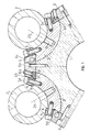
- each spindle receiving sleeve 2 has recesses 4 in adjacent areas, in the assembled state parallel to the edges of the concave slides 3, into which a strip 5 for tensioning and fastening the sleeve 2 by means of screws 5a on the associated concave slide 3 is provided.
- the recesses 4 have an essentially L-shape, the shorter side of the L-shaped receptacles 4, ie the base side 4a, coming into operative connection with the underside 5b of the clamping bar 5.
- the invention are flat pressure pieces 6 for attaching and holding the concave trained slide 3 provided on the body of the platform 1 with the aid of screws 6a (see Fig. 1).
- the pressure pieces 6 have recesses 7 on their underside for inserting an adjusting device 8 in the form of a plate.
- the setting devices 8 can be pressed against the respective longitudinal edges 3a of the associated concave slide 3.
- the adjusting plates 8 can be pressed against the concave slide 3 by screws 8a which can be actuated from the outside.
- the side surfaces 6b, 6c of the clamping pieces 6 and the longer surface 4b of the L-shaped recess 4 in the spindle receiving sleeve 2 are aligned parallel to one another in the assembled state and along the central longitudinal surface of the screws 5a of the clamping strips 5.
- the surfaces 6b, 6c and 4b serve as guide surfaces for adjusting the position of the clamping bar 5 during the assembly of the spindle receiving sleeves.
- a number of threaded bores 9 are provided along the central axis of the concave slide 3, which are used to receive screws 2a for fastening the spindle receiving sleeve 2 to the concave slide 3.
- the number of fixing screws 2a can be chosen freely, practical their number is determined by the length of the spindle receiving sleeve 2.
- the overall length for the recesses 4 on the spindle receiving sleeve 2 and the overall length for the corresponding clamping strips are also determined.
- the recesses 4 could also extend over the entire length of the spindle receiving sleeve 2 or a plurality of recesses 4 could also be provided.
Landscapes
- Engineering & Computer Science (AREA)
- Mechanical Engineering (AREA)
- Jigs For Machine Tools (AREA)
- Turning (AREA)
- Machine Tool Units (AREA)
Applications Claiming Priority (2)
| Application Number | Priority Date | Filing Date | Title |
|---|---|---|---|
| IT2207789 | 1989-10-20 | ||
| IT02207789A IT1236761B (it) | 1989-10-20 | 1989-10-20 | Dispositivo di bloccaggio per il fissaggio dei manicotti portamandrino sulla piattaforma portamandrini di una macchina utensile automatica. |
Publications (2)
| Publication Number | Publication Date |
|---|---|
| EP0423427A2 true EP0423427A2 (fr) | 1991-04-24 |
| EP0423427A3 EP0423427A3 (en) | 1992-01-08 |
Family
ID=11191137
Family Applications (1)
| Application Number | Title | Priority Date | Filing Date |
|---|---|---|---|
| EP19900111157 Withdrawn EP0423427A3 (en) | 1989-10-20 | 1990-06-13 | Clamping device for fixing the sleeve of a spindle onto an automatic machine-tool platform |
Country Status (3)
| Country | Link |
|---|---|
| US (1) | US5113729A (fr) |
| EP (1) | EP0423427A3 (fr) |
| IT (1) | IT1236761B (fr) |
Cited By (2)
| Publication number | Priority date | Publication date | Assignee | Title |
|---|---|---|---|---|
| EP0585690A1 (fr) * | 1992-09-03 | 1994-03-09 | INDEX-WERKE GMBH & CO. KG HAHN & TESSKY | Tour |
| WO2002007900A1 (fr) * | 2000-07-19 | 2002-01-31 | Peter Zimmer Keg | Dispositif d'application de colorant sur une nappe de tissu |
Family Cites Families (7)
| Publication number | Priority date | Publication date | Assignee | Title |
|---|---|---|---|---|
| FR554978A (fr) * | 1922-08-09 | 1923-06-20 | Marqcol | Monture pour outil rotatif tel que scie circulaire, meule et autres |
| US2115236A (en) * | 1932-12-19 | 1938-04-26 | Cincinnati Grinders Inc | Machine tool |
| DE1143689B (de) * | 1958-11-06 | 1963-02-14 | Schiess Ag | Fuehrungs- und Klemmvorrichtung fuer Traghuelsen im Spindelkasten von Fraes- und/oder Bohrwerken |
| DE1243946B (de) * | 1960-09-10 | 1967-07-06 | Schuette Fa Alfred H | Werkzeugschlitten fuer ein- oder mehrspindlige Drehbaenke |
| US4215961A (en) * | 1977-09-20 | 1980-08-05 | Maho Werkzeugmaschinenbau Babel & Co. | Locking mechanism for the mandrel collar on milling and drilling spindles |
| GB1603786A (en) * | 1978-05-24 | 1981-11-25 | White Bsa Tools Ltd | Tool slide principally for a multi-spindle machine tool |
| DE3340102C1 (de) * | 1983-11-05 | 1985-03-28 | Index-Werke Kg Hahn & Tessky, 7300 Esslingen | Vorrichtung zur Befestigung einer Werkzeugaufnahmehuelse auf einem Muldenschlitten einer Werkzeugmaschine |
-
1989
- 1989-10-20 IT IT02207789A patent/IT1236761B/it active IP Right Grant
-
1990
- 1990-06-13 EP EP19900111157 patent/EP0423427A3/de not_active Withdrawn
- 1990-07-23 US US07/557,404 patent/US5113729A/en not_active Expired - Fee Related
Cited By (2)
| Publication number | Priority date | Publication date | Assignee | Title |
|---|---|---|---|---|
| EP0585690A1 (fr) * | 1992-09-03 | 1994-03-09 | INDEX-WERKE GMBH & CO. KG HAHN & TESSKY | Tour |
| WO2002007900A1 (fr) * | 2000-07-19 | 2002-01-31 | Peter Zimmer Keg | Dispositif d'application de colorant sur une nappe de tissu |
Also Published As
| Publication number | Publication date |
|---|---|
| IT8922077A0 (it) | 1989-10-20 |
| US5113729A (en) | 1992-05-19 |
| EP0423427A3 (en) | 1992-01-08 |
| IT8922077A1 (it) | 1991-04-20 |
| IT1236761B (it) | 1993-04-02 |
Similar Documents
| Publication | Publication Date | Title |
|---|---|---|
| EP0328792B1 (fr) | Dispositif de serrage multiple | |
| EP1620219B1 (fr) | Outil de forage | |
| EP2759361A2 (fr) | Dispositif de serrage ou de préhension et mors de base destiné à être utilisé dans un dispositif de serrage ou de préhension | |
| WO1985004126A1 (fr) | Tour | |
| DE10057977A1 (de) | Spannfutter | |
| DE10333061B4 (de) | Bohrkopf | |
| CH662964A5 (de) | Verfahren zur bearbeitung eines werkstuecks in einer drehmaschine zwischen spitzen sowie spannvorrichtung zur durchfuehrung dieses verfahrens. | |
| EP3031556A1 (fr) | Porte-outil | |
| DE3532282C2 (fr) | ||
| EP0423426B1 (fr) | Porte-outil pour tours automatiques | |
| DE19613377B4 (de) | Werkzeugrevolver, insbesondere für Drehmaschinen | |
| EP0362753B1 (fr) | Dispositif de fixation | |
| DE102018007186B4 (de) | Spannbackensystem | |
| EP0379723B1 (fr) | Tour à usiner des gorges équipé d'outils | |
| EP0423427A2 (fr) | Dispositif de serrage pour fixer la douille d'une broche sur la plateforme d'une machine-outil automatique | |
| DE3400082A1 (de) | Verfahren zur bearbeitung eines werkstuecks in einer drehmaschine zwischen spitzen sowie spannvorrichtung zur durchfuehrung dieses verfahrens | |
| DE102016012169A1 (de) | Spannvorrichtung | |
| EP2101944B1 (fr) | Outil d'usinage à enlèvement de copeaux | |
| DE3716933C2 (de) | Werkstück-Zuführeinrichtung an einer Werkzeugmaschine, insbesondere Drehmaschine | |
| DE2257653C3 (de) | Bohrkopf | |
| DE4012468C2 (fr) | ||
| DE3312990C2 (de) | Ausdrehwerkzeug | |
| DE19951931B4 (de) | Fräswerkzeug, insbesondere Fräskopf zum Plan- und Eckfräsen | |
| EP0504995B1 (fr) | Mâchoires d'appointage par pincement | |
| DE102009044497B4 (de) | Spanneinrichtungssystem |
Legal Events
| Date | Code | Title | Description |
|---|---|---|---|
| PUAI | Public reference made under article 153(3) epc to a published international application that has entered the european phase |
Free format text: ORIGINAL CODE: 0009012 |
|
| AK | Designated contracting states |
Kind code of ref document: A2 Designated state(s): AT CH DE ES FR GB IT LI |
|
| PUAL | Search report despatched |
Free format text: ORIGINAL CODE: 0009013 |
|
| AK | Designated contracting states |
Kind code of ref document: A3 Designated state(s): AT CH DE ES FR GB IT LI |
|
| 17P | Request for examination filed |
Effective date: 19920617 |
|
| 17Q | First examination report despatched |
Effective date: 19920821 |
|
| STAA | Information on the status of an ep patent application or granted ep patent |
Free format text: STATUS: THE APPLICATION HAS BEEN WITHDRAWN |
|
| 18W | Application withdrawn |
Withdrawal date: 19930302 |