EP0423519A2 - Transporteur pour le transfert de pots de filature et utilisation du transporteur - Google Patents
Transporteur pour le transfert de pots de filature et utilisation du transporteur Download PDFInfo
- Publication number
- EP0423519A2 EP0423519A2 EP90118570A EP90118570A EP0423519A2 EP 0423519 A2 EP0423519 A2 EP 0423519A2 EP 90118570 A EP90118570 A EP 90118570A EP 90118570 A EP90118570 A EP 90118570A EP 0423519 A2 EP0423519 A2 EP 0423519A2
- Authority
- EP
- European Patent Office
- Prior art keywords
- feed rod
- cans
- rod
- transport
- driver
- Prior art date
- Legal status (The legal status is an assumption and is not a legal conclusion. Google has not performed a legal analysis and makes no representation as to the accuracy of the status listed.)
- Granted
Links
- 238000009987 spinning Methods 0.000 claims abstract description 12
- 238000002360 preparation method Methods 0.000 claims abstract description 4
- 239000000969 carrier Substances 0.000 claims description 9
- 239000000835 fiber Substances 0.000 description 6
- 239000000463 material Substances 0.000 description 5
- 238000000926 separation method Methods 0.000 description 4
- 229910000831 Steel Inorganic materials 0.000 description 3
- 239000010959 steel Substances 0.000 description 3
- 238000004140 cleaning Methods 0.000 description 2
- 230000000694 effects Effects 0.000 description 2
- 230000002349 favourable effect Effects 0.000 description 2
- 238000003860 storage Methods 0.000 description 2
- 239000004753 textile Substances 0.000 description 2
- 229910000975 Carbon steel Inorganic materials 0.000 description 1
- 206010017577 Gait disturbance Diseases 0.000 description 1
- 239000010962 carbon steel Substances 0.000 description 1
- 230000003670 easy-to-clean Effects 0.000 description 1
- 230000037431 insertion Effects 0.000 description 1
- 238000003780 insertion Methods 0.000 description 1
- 230000002265 prevention Effects 0.000 description 1
- 238000005096 rolling process Methods 0.000 description 1
- 238000003466 welding Methods 0.000 description 1
- 239000002023 wood Substances 0.000 description 1
Images
Classifications
-
- D—TEXTILES; PAPER
- D01—NATURAL OR MAN-MADE THREADS OR FIBRES; SPINNING
- D01H—SPINNING OR TWISTING
- D01H9/00—Arrangements for replacing or removing bobbins, cores, receptacles, or completed packages at paying-out or take-up stations ; Combination of spinning-winding machine
- D01H9/18—Arrangements for replacing or removing bobbins, cores, receptacles, or completed packages at paying-out or take-up stations ; Combination of spinning-winding machine for supplying bobbins, cores, receptacles, or completed packages to, or transporting from, paying-out or take-up stations ; Arrangements to prevent unwinding of roving from roving bobbins
- D01H9/185—Transporting cans
-
- B—PERFORMING OPERATIONS; TRANSPORTING
- B65—CONVEYING; PACKING; STORING; HANDLING THIN OR FILAMENTARY MATERIAL
- B65H—HANDLING THIN OR FILAMENTARY MATERIAL, e.g. SHEETS, WEBS, CABLES
- B65H67/00—Replacing or removing cores, receptacles, or completed packages at paying-out, winding, or depositing stations
- B65H67/04—Arrangements for removing completed take-up packages and or replacing by cores, formers, or empty receptacles at winding or depositing stations; Transferring material between adjacent full and empty take-up elements
- B65H67/0428—Arrangements for removing completed take-up packages and or replacing by cores, formers, or empty receptacles at winding or depositing stations; Transferring material between adjacent full and empty take-up elements for cans, boxes and other receptacles
-
- B—PERFORMING OPERATIONS; TRANSPORTING
- B65—CONVEYING; PACKING; STORING; HANDLING THIN OR FILAMENTARY MATERIAL
- B65G—TRANSPORT OR STORAGE DEVICES, e.g. CONVEYORS FOR LOADING OR TIPPING, SHOP CONVEYOR SYSTEMS OR PNEUMATIC TUBE CONVEYORS
- B65G25/00—Conveyors comprising a cyclically-moving, e.g. reciprocating, carrier or impeller which is disengaged from the load during the return part of its movement
- B65G25/04—Conveyors comprising a cyclically-moving, e.g. reciprocating, carrier or impeller which is disengaged from the load during the return part of its movement the carrier or impeller having identical forward and return paths of movement, e.g. reciprocating conveyors
- B65G25/08—Conveyors comprising a cyclically-moving, e.g. reciprocating, carrier or impeller which is disengaged from the load during the return part of its movement the carrier or impeller having identical forward and return paths of movement, e.g. reciprocating conveyors having impellers, e.g. pushers
- B65G25/12—Conveyors comprising a cyclically-moving, e.g. reciprocating, carrier or impeller which is disengaged from the load during the return part of its movement the carrier or impeller having identical forward and return paths of movement, e.g. reciprocating conveyors having impellers, e.g. pushers with impeller fixed to a reciprocating bar and the bar being rotated about its longitudinal axis on its return stroke
-
- B—PERFORMING OPERATIONS; TRANSPORTING
- B65—CONVEYING; PACKING; STORING; HANDLING THIN OR FILAMENTARY MATERIAL
- B65H—HANDLING THIN OR FILAMENTARY MATERIAL, e.g. SHEETS, WEBS, CABLES
- B65H2701/00—Handled material; Storage means
- B65H2701/30—Handled filamentary material
- B65H2701/31—Textiles threads or artificial strands of filaments
Definitions
- the invention relates to a transport path for the gradual sliding forwarding of cans in the spinning preparation or spinning mill with a push rod which can be moved back and forth in the transport direction and carriers attached to it for grasping the respective can during feed.
- slivers are transported to and from lines as well as flyers or spinning machines with the help of so-called spinning cans, or cans for short. After filling or empty, each jug must be replaced by a new, empty or filled jug. If necessary, the cans can be transported further using roller conveyors, overhead conveyors or conveyor belts.
- a can change and transport device for spinning preparation machines, in which the transport tracks are made of conveyor belts, is described in DE-AS 12 65 014.
- a corresponding device in which the conveyor lines are designed as roller conveyors is specified in DE-OS 38 09 282.
- DE-AS 19 64 857 it is also possible to transport the cans on slideways between guide rails with the aid of transport chains.
- roller conveyors, conveyor belts or transport chains either have to be sunk into the ground or appear as a step of approximately 200 to 300 mm in height. Either trenches must therefore be provided in the respective factory building, or a considerable risk of accidents due to stumbling or a block against rolling cross traffic must be accepted.
- a transport path of the type mentioned can be found in DE-OS 31 33 438.
- Known are provided on the feed rod pivotally mounted drivers, which are spread apart by a spring force against a stop connected to the rod from the rod. When the bar is moved back and forth in its longitudinal direction, the drivers either reach behind a can and push it further in the longitudinal direction of the bar, or they slide along the respective can against the spring force when it moves back.
- a disadvantage of the known device is that the Cans are only to be advanced in pairs, the feed rod being arranged between two rows of cans, and that the rows of cans require additional sliding guides on the outside of the bar facing away from the cans.
- the known device is so stiff due to the point of attack of the driver and by sliding both on the floor and on side guides that the cans - with a correspondingly strong drive of the feed rod - are quickly dented by the lateral attack of the driver.
- the known driver system must be combined with roller conveyors.
- the invention has for its object to provide a can conveyor with clock feed for a single row of cans, in which side guides of the cans are not required and which meets the accident prevention regulations and has such a low height that it can be accepted as a threshold .
- a straight push rod is mounted approximately in the middle between two slide rails, possibly carrying a single row of cans, that the carriers are in a single.
- Approximately radially with respect to the longitudinal axis of the push rod extending at a mutual distance of at most the can division are immovably attached to the push rod and that the push rod sum upright and put aside the drivers pivot about 90 ° around their longitudinal axis bar and at least a carrier distance, in particular plus twice the thickness of a can edge to be detected, is mounted so that it can be pushed back and forth in the transport direction.
- the invention is based on the finding that the can transporter having the push rod with carriers usually only has to be carried out at relatively large time intervals of, for example, 1/4 to 1/2 hour.
- the cans are therefore mostly stationary and can be moved relatively slowly if necessary.
- Such transport can be effected easily and with great precision with regard to the positioning of the individual can with the aid of the feed rod according to the invention.
- a fast forward movement of the can is also without disadvantages for the positioning accuracy within the scope of the invention.
- fiber coils cannot be formed on the moving parts of the transport path, because the moving parts, namely the feed rod, only perform reciprocating movements in the longitudinal direction or in the circumferential direction. Any adhering fibers are even automatically repelled by the back and forth movement. If fibers should nevertheless accumulate, the transport path, e.g. with the help of compressed air, easy to clean, because only the straight rod and its bearings are to be kept clean and no fiber coils can arise.
- an extraordinarily low overall height of the transport path is achieved by the invention because le above the floor diglich a - to be trained as a steel tube - rod, for example, 20 mm in diameter, longitudinally displaceable and pivotable about the longitudinal axis.
- the overall height can be limited to 25 to 35 mm.
- a threshold of this height on the factory floor is perceived by the staff as not significantly annoying when walking. The threshold can even be crossed by the vehicles used in a factory.
- Another advantage of the invention is that all that is required as a conveyor is a linearly reciprocating rod which is pivoted about its axis and the associated drives. Compared to chain drives, conveyor belts or even roller conveyors, relatively low investment and assembly costs are therefore incurred.
- the drivers are set up for a can feed and then reach from below into the usual hollow bottom space of the can, so that when the feed rod is moved forward, one of its drivers engages the inner lower edge of the can, which essentially forms a cylindrical continuation of the can wall. At least then, i.e. when the can is being fed, the rod lies on a line that runs through the longitudinal axis of the can (center line).
- This mutual assignment has the effect that the frictional force between the can and the bottom or the guide is not increased by the engagement of the driver, but rather is reduced. It is therefore unnecessary to facilitate feed by roller conveyors or the like, rather simple slide rails are sufficient as the conveying path of the cans.
- the feed rod extending over a predetermined transport path is provided as the transporter of the cans sliding on slide rails.
- the latter is a certain amount in its longitudinal direction, the rod stroke, e.g. of the order of 150 mm, can be pushed back and forth and can be pivoted back and forth by about 90 ° in the circumferential direction.
- a series of carriers which project substantially radially in a single plane are firmly attached to the rod.
- the mutual distance between adjacent carriers should at most be so large that an upright carrier, which grips a lower edge of the can from the side of the can, after one advance and a subsequent return movement of the rod (in the pivoted-down position) for a further advance under the next one Can be erected and with the new feed can grasp the other edge of the can from the inside.
- the cans are moved forwards or backwards step by step by means of the longitudinal and swiveling movement of the feed rod.
- the feed rod is first pivoted so that the drivers stand up and reach under the cans arranged above.
- the rod is moved forward in the respective forward direction by an amount up to the maximum stroke, for example by the aforementioned 150 mm.
- the rod is pivoted back 90 ° (about its longitudinal direction) so that the drivers can slide under the cans without touching them.
- the rod is then moved back in a fourth step with the carriers lowered by the previous stroke and pivoted again by 90 °, so that the carriers stand up again and the cans are to be pushed forward or moved on by the next stroke when the rod is moved forward.
- the cans should slide on two rail-like strips during forward transport, which are arranged on both sides of the feed rod with a sufficient distance for a stable stand.
- the slide rails should preferably consist of a plastic on which the material of the cans slides particularly well. If the slide rails on both sides of the bar do not directly adjoin the housing parts that may receive the bar, the intermediate area can be filled in order to obtain a sufficiently slip-resistant surface of the transport path. For example, wooden panels can be used for filling.
- the feed rod according to the invention is only to be stored in sliding guides which permit a back-and-forth movement and a pivoting by 90 °, a structural height of 25 to 35 mm can be easily maintained.
- the assembly can be carried out without difficulty even with slightly wavy, uneven floors.
- a crank drive is preferably provided which be a sinusoidal feed works. This ensures that the movement of the rod begins slowly at the dead center of the crank drive and stops slowly. So when starting, there are no blows to the cans. When braking, there is no need to fear that the cans will follow. The cans must therefore be positioned exactly.
- the number of drivers of the push rod is in itself arbitrary.
- the carrier distance may at most be equal to the pitch of the can if each can is to be grasped by a carrier during can transport.
- the driver division can also be made more or less smaller than the can division. It is advantageous if the can division is chosen to be an integer multiple of the carrier division (carrier distance).
- separate bearings are preferably provided for the push rod, namely for the pivoting movement on the one hand and for the longitudinal movement on the other hand. This makes it possible to reach any position in the longitudinal direction with any driver.
- the bearing division can also be selected independently of the distance between the drivers. Accordingly, there is the possibility of a pitch-independent advance of the cans to be transported.
- the separation of the longitudinal and pivot bearings of the rod is achieved in that the feed rod for the pivoting movement is accommodated in bearing blocks, while the bearing blocks for the longitudinal movement are slidably supported in a rail.
- the bearing blocks can also be relative to the rod, for example by random forces, be longitudinally displaceable.
- the position of the bearing blocks relatively fixed relative to the rod length, so that there is a strict separation of the longitudinal and swivel bearings of the rod.
- each bearing block is allowed to have a fixed position along the length of the rod, it can be advantageous to attach the drivers to the rod within each block.
- a slot running radially with respect to the rod is then provided in the respective bearing block, which allows the driver to pivot about 90 °.
- the side of the bearing block having the slot is bevelled so that the Shear angle between the driver and the bearing block bevel is greater than 90 °. A finger or the like that happens to come into this area is not sheared off, but pushed to the side.
- the arrangement of the driver within the - as described - slanted bearing block is particularly favorable, because if the driver is arranged anywhere outside the bearing blocks and if the bearing blocks move in the longitudinal direction of the bar, a relative position of the bearing block and driver can always occur which there is an increased risk of shear at the border between driver and bearing block.
- the invention is therefore preferably used in spinning cans, but can also bring considerable advantages in connection with other objects.
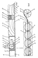
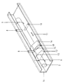
- FIG. 1 and 2 schematically illustrate a transport path, generally designated 1, for the sliding forwarding of cans 2.
- Driver 8 protrude from the feed rod 3 in a plane 7 that extends approximately radially with respect to the longitudinal axis 6 of the rod.
- the feed rod 3 is pivoted about the axis 6 about its axis 6 in the circumferential direction 9 to erect and set aside the driver 8 and at least the rod stroke H in the direction of its longitudinal axis 6 back and forth.
- the rod 3 can consist of steel tube, for example 20 mm in diameter.
- Each driver 8 can also be made of steel with a diameter of 8 mm, for example, and be immovably connected to the rod 3, for example by welding.
- the length L of the driver 8 is chosen so that the vertically erected driver 8 under the bottom of one 1 or 2 standing jug protrudes and takes the jug 2 by moving in the transport direction 11 by attacking the inner wall of the lower edge.
- the feed rod 3 can be received over its entire length or at individual locations in half bearings 10.
- the material expenditure for a suitable slide material becomes very considerable. If individual bearing blocks 12 designed as half-bearings 10 are used, the material expenditure is tolerable, but the storage stability cannot be felt as sufficient. However, a bearing that encompasses the entire rod cannot be used without further ado because the longitudinal movement of the driver 8 would then be impeded. If slots are made in the bearing accordingly, the drivers 8 can move longitudinally through the respective bearing, but they represent very dangerous shear points.
- the driver 8 is fastened to the rod 3 within the bearing block 12.
- the bearing block 12 has a radially extending with respect to the rod 3 slot 15, which is just large in the circumferential direction and in the radial direction with respect to the rod 3 that a substantially smooth pivoting of the driver 8 in the circumferential direction 9 (back and forth) can take place.
- the top 16 of the bearing block 12 having the slot 15 is chamfered in such a way that the shear angle between the driver 8 and the inclination of the top 16 is greater than 90 ° everywhere.
- the cans 2 to be moved further according to the invention are generally close to one another or with a predetermined mutual distance on the transport path 1. They slide on the slide rails 4 and are moved further in the respective transport direction 11 by the clock movement of the feed rod 3.
- a sliding plane 17 is defined by the upper edge of the slide rails 4, over which the erected drivers 8 project upwards. The driver 8 are for one Attack on the cans 2, but in the opposite direction (back movement) by pivoting about the longitudinal axis 6 in the dashed side position 18 (see FIGS. 1 and 3) lowered below the sliding plane 17.
- a cover 19 can be arranged at a distance a below the sliding plane 17 that does not hinder the advancement of the cans 2.
- a longitudinal slot 20 is provided in the cover 19, which slot should be present essentially over the entire length of the rod 3 and should be so wide that the driver 8 has no risk of accidents, ie at a distance can pivot past the edge 21 of the longitudinal slot 20 opposite the driver 8.
- a housing designated overall by 22, is provided for storing the feed rod 3, the upper side of which is located somewhat below the sliding plane 17. If the housing 22 does not reach the slide rail horizontally, the space can be closed by means of a plate, e.g. made of wood. The remaining part of the transport path 1 below the respective can 2 outside the slide rails 4 (with reference to the rod 3) can be raised to the level of the housing 22 with the aid of a plate 24, such that the transport path 1 as a whole is essentially practical is just.
- the slide rail 4 is made in the exemplary embodiment from a plastic on which the material of the cans 2 slides particularly well.
- the actual plastic profile 25 is preferably connected to a load-bearing carbon steel profile 26 at only one point in order to ensure automatic compensation of thermal changes in length. Only the C-profile 26 is screwed to the bottom 27 of the transport track 1, possibly with the insertion of a strip 28.
- a drive crank 29 is preferably provided as the drive of the feed rod 3 according to the invention, the crank rod 30 of which acts on the feed rod 3 via a crosshead 32 when rotated in the direction of the arrow 31. If one places the beginning and the end of the respective feed movement at the point at which the crank rod 30 lies in the plane of the axis 33 of the thrust crank 29, the movement of the feed rod 3 begins at a dead center and ends at a dead center of the crank mechanism.
- a drive of the rod 3 with the aid of a cylinder, a spindle or the like is also possible.
- An embodiment in which the mutual distance between the drivers corresponds to an integer divider of the can division is particularly desirable when cans are to be transferred from one transport path to another, which runs, for example, perpendicular to the first. This can happen if the driver of the feed rod of the one path pushes the can into the access area of the driver of the feed rod of the other path without the feed rods crossing each other.
Landscapes
- Engineering & Computer Science (AREA)
- Mechanical Engineering (AREA)
- Textile Engineering (AREA)
- Spinning Or Twisting Of Yarns (AREA)
- Spinning Methods And Devices For Manufacturing Artificial Fibers (AREA)
- Replacing, Conveying, And Pick-Finding For Filamentary Materials (AREA)
Applications Claiming Priority (2)
| Application Number | Priority Date | Filing Date | Title |
|---|---|---|---|
| DE3934816 | 1989-10-19 | ||
| DE3934816 | 1989-10-19 |
Publications (3)
| Publication Number | Publication Date |
|---|---|
| EP0423519A2 true EP0423519A2 (fr) | 1991-04-24 |
| EP0423519A3 EP0423519A3 (en) | 1991-09-18 |
| EP0423519B1 EP0423519B1 (fr) | 1994-11-30 |
Family
ID=6391746
Family Applications (1)
| Application Number | Title | Priority Date | Filing Date |
|---|---|---|---|
| EP90118570A Expired - Lifetime EP0423519B1 (fr) | 1989-10-19 | 1990-09-27 | Transporteur pour le transfert de pots de filature et utilisation du transporteur |
Country Status (4)
| Country | Link |
|---|---|
| US (1) | US5115631A (fr) |
| EP (1) | EP0423519B1 (fr) |
| DE (1) | DE59007846D1 (fr) |
| ES (1) | ES2065455T3 (fr) |
Cited By (5)
| Publication number | Priority date | Publication date | Assignee | Title |
|---|---|---|---|---|
| EP0612871A1 (fr) * | 1993-02-26 | 1994-08-31 | Rosink GmbH + Co. KG | Dispositif de transport |
| US5816381A (en) * | 1994-08-10 | 1998-10-06 | W. Schlafhorst Ag & Co. | Transport apparatus for textile packages, transport system and automatic can transport vehicle having the transport apparatus |
| EP0825284A3 (fr) * | 1996-08-16 | 1999-02-03 | Manfred Langen | Transporteur sans fin |
| KR100709311B1 (ko) * | 2000-06-28 | 2007-04-20 | 에스.씨. 존슨 앤드 선, 인코포레이티드 | 입자 포착 시스템 |
| CN108100505A (zh) * | 2017-12-08 | 2018-06-01 | 南通元创卓宇纺织品有限公司 | 一种可调节棉纺运输与卸料设备 |
Families Citing this family (4)
| Publication number | Priority date | Publication date | Assignee | Title |
|---|---|---|---|---|
| DE9210330U1 (de) * | 1992-08-01 | 1992-11-26 | Innovatex Unternehmensberatung GmbH, 4050 Mönchengladbach | Einrichtung zum Transport und Austausch von Spinnkannen |
| CN110318129B (zh) * | 2019-08-06 | 2024-12-03 | 湖北天门纺织机械股份有限公司 | 一种并条机自动抬杆装置 |
| ES2956740B2 (es) * | 2022-05-18 | 2024-04-29 | Trias Juan Rovira | Dispositivo de transporte de objetos |
| CN116253208A (zh) * | 2023-02-01 | 2023-06-13 | 安徽省无为天成纺织有限公司 | 一种纺线棒及针对该纺线棒的上料、辅助放线系统 |
Family Cites Families (12)
| Publication number | Priority date | Publication date | Assignee | Title |
|---|---|---|---|---|
| US3125782A (en) * | 1961-04-08 | 1964-03-24 | Automatic can replacing apparatus for -a drawing frame | |
| DE1265014B (de) * | 1963-01-12 | 1968-03-28 | Schubert & Salzer Maschinen | Kannenwechsel- und -transportvorrichtung fuer Spinnereivorbereitungsmaschinen |
| US3214799A (en) * | 1963-05-20 | 1965-11-02 | Gossett Machine Works Inc | Automatic can doffers for sliver processing machines |
| JPS5218928A (en) * | 1975-07-17 | 1977-02-12 | Hara Shokki Seisakusho Kk | Apparatus for trnsfering kence in spinning machine |
| US4089203A (en) * | 1976-04-07 | 1978-05-16 | Wallis Bernard J | Workpiece transfer mechanism |
| JPS5357674A (en) * | 1976-11-02 | 1978-05-25 | Yoshida Kogyo Kk | Element feeder |
| DE2821325A1 (de) * | 1978-05-16 | 1979-11-22 | Schlafhorst & Co W | Verfahren und vorrichtung zum fuellen rotierender faserbandkannen |
| DE3133438C2 (de) * | 1981-08-24 | 1983-11-03 | Heberlein Hispano S.A., 1214 Vernier-Genève | Verfahren und Vorrichtung zum automatischen Wechsen gefüllter Kannen gegen leere Kannen an einer Doppelkopfstrecke |
| EP0082938A1 (fr) * | 1981-12-22 | 1983-07-06 | Maschinenfabrik Rieter Ag | Dispositif pour déplacer des pots de machine de préparation à la filature |
| JPS5974865A (ja) * | 1982-10-23 | 1984-04-27 | Toyoda Autom Loom Works Ltd | 紡機におけるケンス管理装置 |
| IT1210039B (it) * | 1982-12-29 | 1989-09-06 | Savio Spa | Trasportatore a passo di tubetti er macchine tessili. |
| DE3809282A1 (de) * | 1988-03-19 | 1989-09-28 | Klaus Hoffmann | Vorrichtung zum zu- und abfuehren von kannen |
-
1990
- 1990-09-27 ES ES90118570T patent/ES2065455T3/es not_active Expired - Lifetime
- 1990-09-27 DE DE59007846T patent/DE59007846D1/de not_active Expired - Fee Related
- 1990-09-27 EP EP90118570A patent/EP0423519B1/fr not_active Expired - Lifetime
- 1990-10-02 US US07/591,942 patent/US5115631A/en not_active Expired - Fee Related
Cited By (8)
| Publication number | Priority date | Publication date | Assignee | Title |
|---|---|---|---|---|
| EP0612871A1 (fr) * | 1993-02-26 | 1994-08-31 | Rosink GmbH + Co. KG | Dispositif de transport |
| DE4305916A1 (de) * | 1993-02-26 | 1994-09-01 | Rosink Gmbh & Co Kg | Transportvorrichtung |
| US5816381A (en) * | 1994-08-10 | 1998-10-06 | W. Schlafhorst Ag & Co. | Transport apparatus for textile packages, transport system and automatic can transport vehicle having the transport apparatus |
| DE4428247B4 (de) * | 1994-08-10 | 2004-04-22 | Saurer Gmbh & Co. Kg | Transportvorrichtung für textile Packungen |
| EP0825284A3 (fr) * | 1996-08-16 | 1999-02-03 | Manfred Langen | Transporteur sans fin |
| US5881861A (en) * | 1996-08-16 | 1999-03-16 | Langen; Manfred | Circulating conveyor |
| KR100709311B1 (ko) * | 2000-06-28 | 2007-04-20 | 에스.씨. 존슨 앤드 선, 인코포레이티드 | 입자 포착 시스템 |
| CN108100505A (zh) * | 2017-12-08 | 2018-06-01 | 南通元创卓宇纺织品有限公司 | 一种可调节棉纺运输与卸料设备 |
Also Published As
| Publication number | Publication date |
|---|---|
| EP0423519A3 (en) | 1991-09-18 |
| US5115631A (en) | 1992-05-26 |
| ES2065455T3 (es) | 1995-02-16 |
| DE59007846D1 (de) | 1995-01-12 |
| EP0423519B1 (fr) | 1994-11-30 |
Similar Documents
| Publication | Publication Date | Title |
|---|---|---|
| AT506221B1 (de) | Verfahren und transportvorrichtung zum positionieren von ladehilfsmitteln vor deren übergabe in ein regalfach | |
| EP0407703B1 (fr) | Procédé et dispositif pour stocker et déstocker des caissons contenant des matériaux en forme de bâton ou de plaque dans un magasin à rayonnage | |
| DE2543621C2 (de) | Kannenwechseleinrichtung | |
| EP1638866A1 (fr) | Procede et dispositif pour manipuler des auxiliaires de chargement | |
| AT510537A1 (de) | Verfahren zum einlagern von waren sowie vorrichtung dazu | |
| EP0574851A1 (fr) | Paroi de séparation constituée d'éléments déplaçables | |
| DE3504491A1 (de) | Vorrichtung zum anlegen von bogen | |
| DE9103197U1 (de) | Regalbediengerät für Hochregallager | |
| WO2007036250A1 (fr) | Systeme de stockage a rotation horizontale | |
| EP1038819A1 (fr) | Dispositif de triage et d'accumulation sélective d'objets plats | |
| EP0423519B1 (fr) | Transporteur pour le transfert de pots de filature et utilisation du transporteur | |
| EP1832529A2 (fr) | Transstockeur avec un élement de stockage intermédiaire dans un magasin a rayonnage comportant des tiroirs montés dans les compartiments de rayonnage | |
| DE2915095C2 (de) | Fördereinrichtung, insbesondere für Hängeförderung | |
| EP0968938A1 (fr) | Etagère inclinée pour la préparation de commandes à partir des unités de stockage | |
| DE3035338A1 (de) | Lagergestell fuer auf paletten abgestellte bierfaesser, flaschenkaesten u.dgl. | |
| DE4428247A1 (de) | Transportvorrichtung für textile Packungen | |
| DE4025647A1 (de) | Transportbahn zum weiterleiten von kannen | |
| DE3710916A1 (de) | Vorrichtung zur fuehrung von paletten auf einer rollenbahn | |
| DE19720102A1 (de) | Vorrichtung zum Führen von Werkstücken | |
| DE4142790C2 (de) | Kopstransporteinrichtung in einem Spulautomaten | |
| EP0737642A2 (fr) | Machine de frisage | |
| EP0983949B1 (fr) | Méthode et dispositif pour l'alimentation de profilés creux vers une machine à plier dans la fabrication de vitres isolantes | |
| DE3917891C2 (fr) | ||
| DD262221A5 (de) | Kassettenbewegungswerk, insb. zum bewegen von in kassetten untergebrachten stabstahlguetern | |
| DE4113092C2 (de) | Zapfenschlitten-Überführungsvorrichtung an einer Ringspinnmaschine |
Legal Events
| Date | Code | Title | Description |
|---|---|---|---|
| PUAI | Public reference made under article 153(3) epc to a published international application that has entered the european phase |
Free format text: ORIGINAL CODE: 0009012 |
|
| AK | Designated contracting states |
Kind code of ref document: A2 Designated state(s): CH DE ES FR GB IT LI |
|
| PUAL | Search report despatched |
Free format text: ORIGINAL CODE: 0009013 |
|
| AK | Designated contracting states |
Kind code of ref document: A3 Designated state(s): CH DE ES FR GB IT LI |
|
| 17P | Request for examination filed |
Effective date: 19910814 |
|
| 17Q | First examination report despatched |
Effective date: 19930803 |
|
| GRAA | (expected) grant |
Free format text: ORIGINAL CODE: 0009210 |
|
| AK | Designated contracting states |
Kind code of ref document: B1 Designated state(s): CH DE ES FR GB IT LI |
|
| REF | Corresponds to: |
Ref document number: 59007846 Country of ref document: DE Date of ref document: 19950112 |
|
| ITF | It: translation for a ep patent filed | ||
| REG | Reference to a national code |
Ref country code: ES Ref legal event code: FG2A Ref document number: 2065455 Country of ref document: ES Kind code of ref document: T3 |
|
| GBT | Gb: translation of ep patent filed (gb section 77(6)(a)/1977) |
Effective date: 19950202 |
|
| ET | Fr: translation filed | ||
| PGFP | Annual fee paid to national office [announced via postgrant information from national office to epo] |
Ref country code: DE Payment date: 19950719 Year of fee payment: 6 |
|
| PGFP | Annual fee paid to national office [announced via postgrant information from national office to epo] |
Ref country code: FR Payment date: 19950904 Year of fee payment: 6 |
|
| PGFP | Annual fee paid to national office [announced via postgrant information from national office to epo] |
Ref country code: ES Payment date: 19950919 Year of fee payment: 6 |
|
| PLBE | No opposition filed within time limit |
Free format text: ORIGINAL CODE: 0009261 |
|
| STAA | Information on the status of an ep patent application or granted ep patent |
Free format text: STATUS: NO OPPOSITION FILED WITHIN TIME LIMIT |
|
| PGFP | Annual fee paid to national office [announced via postgrant information from national office to epo] |
Ref country code: CH Payment date: 19951117 Year of fee payment: 6 |
|
| 26N | No opposition filed | ||
| PG25 | Lapsed in a contracting state [announced via postgrant information from national office to epo] |
Ref country code: ES Free format text: LAPSE BECAUSE OF THE APPLICANT RENOUNCES Effective date: 19960928 |
|
| PG25 | Lapsed in a contracting state [announced via postgrant information from national office to epo] |
Ref country code: LI Effective date: 19960930 Ref country code: FR Effective date: 19960930 Ref country code: CH Effective date: 19960930 |
|
| GBPC | Gb: european patent ceased through non-payment of renewal fee |
Effective date: 19960927 |
|
| REG | Reference to a national code |
Ref country code: CH Ref legal event code: PL |
|
| PG25 | Lapsed in a contracting state [announced via postgrant information from national office to epo] |
Ref country code: DE Effective date: 19970603 |
|
| REG | Reference to a national code |
Ref country code: FR Ref legal event code: ST |
|
| REG | Reference to a national code |
Ref country code: FR Ref legal event code: ST |
|
| REG | Reference to a national code |
Ref country code: GB Ref legal event code: 728V |
|
| REG | Reference to a national code |
Ref country code: ES Ref legal event code: FD2A Effective date: 19991007 |
|
| PGFP | Annual fee paid to national office [announced via postgrant information from national office to epo] |
Ref country code: GB Payment date: 20001011 Year of fee payment: 11 |
|
| REG | Reference to a national code |
Ref country code: GB Ref legal event code: 732E Ref country code: GB Ref legal event code: 728Y |
|
| PG25 | Lapsed in a contracting state [announced via postgrant information from national office to epo] |
Ref country code: GB Free format text: LAPSE BECAUSE OF NON-PAYMENT OF DUE FEES Effective date: 20010927 |
|
| REG | Reference to a national code |
Ref country code: GB Ref legal event code: IF02 |
|
| GBPC | Gb: european patent ceased through non-payment of renewal fee |
Effective date: 20010927 |
|
| PG25 | Lapsed in a contracting state [announced via postgrant information from national office to epo] |
Ref country code: IT Free format text: LAPSE BECAUSE OF NON-PAYMENT OF DUE FEES;WARNING: LAPSES OF ITALIAN PATENTS WITH EFFECTIVE DATE BEFORE 2007 MAY HAVE OCCURRED AT ANY TIME BEFORE 2007. THE CORRECT EFFECTIVE DATE MAY BE DIFFERENT FROM THE ONE RECORDED. Effective date: 20050927 |