EP0423578A2 - Sicherungsgehäuse - Google Patents
Sicherungsgehäuse Download PDFInfo
- Publication number
- EP0423578A2 EP0423578A2 EP90119230A EP90119230A EP0423578A2 EP 0423578 A2 EP0423578 A2 EP 0423578A2 EP 90119230 A EP90119230 A EP 90119230A EP 90119230 A EP90119230 A EP 90119230A EP 0423578 A2 EP0423578 A2 EP 0423578A2
- Authority
- EP
- European Patent Office
- Prior art keywords
- insulating part
- fuse
- electrically conductive
- base
- screw thread
- Prior art date
- Legal status (The legal status is an assumption and is not a legal conclusion. Google has not performed a legal analysis and makes no representation as to the accuracy of the status listed.)
- Granted
Links
Images


Classifications
-
- H—ELECTRICITY
- H01—ELECTRIC ELEMENTS
- H01H—ELECTRIC SWITCHES; RELAYS; SELECTORS; EMERGENCY PROTECTIVE DEVICES
- H01H85/00—Protective devices in which the current flows through a part of fusible material and this current is interrupted by displacement of the fusible material when this current becomes excessive
- H01H85/02—Details
- H01H85/30—Means for indicating condition of fuse structurally associated with the fuse
-
- H—ELECTRICITY
- H01—ELECTRIC ELEMENTS
- H01H—ELECTRIC SWITCHES; RELAYS; SELECTORS; EMERGENCY PROTECTIVE DEVICES
- H01H85/00—Protective devices in which the current flows through a part of fusible material and this current is interrupted by displacement of the fusible material when this current becomes excessive
- H01H85/54—Protective devices wherein the fuse is carried, held, or retained by an intermediate or auxiliary part removable from the base, or used as sectionalisers
- H01H85/62—Protective devices wherein the fuse is carried, held, or retained by an intermediate or auxiliary part removable from the base, or used as sectionalisers the intermediate or auxiliary part being adapted for screwing into the base
Definitions
- the invention relates to a fuse housing according to the preamble of claim 1.
- Fuses which serve to protect electrical line networks, are generally accommodated in a housing which is formed from a head made of electrically insulating material and a metal sleeve which is partially surrounded by the head.
- the fuse is brought into contact with a connecting element located in a base by screwing the head with the metal sleeve and the fuse located therein into the base.
- the head is approximately pot-shaped and has a central through opening in its pot bottom, which is closed with a glass pane and a spring clip holding the glass pane.
- the glass pane allows a view of the inside of the head towards the fuse plate on the front of the fuse so that you can see whether the fuse has melted or not.
- the head has three parts.
- the object of the invention is to provide fuse housings of the type mentioned at the outset, which are of simplified construction and can be assembled in a simplified manner.
- the base of the pot can be designed like a lens or magnifying glass at least in a central region, as a result of which the securing plate is visible in an enlarged manner, so that the response of the securing device can be assessed more easily.
- a wall thickness which is thinner than the remaining area of the insulating part can be provided in a central area. This also provides an optimal view of the safety plate. Because of a somewhat simplified tool, this version with the thinner wall thickness can be somewhat cheaper than the version with the lens-like or magnifying glass-like thickening.
- the inside of the head is provided with latching means which engage with latching means on the sleeve for the firm connection of the sleeve and the pot.
- Another attachment of the electrically conductive element to the bottom of the pot can be done in that at least one knob is formed on the inside of the bottom of the pot, which in an electrically adapted opening in the engages conductive element and is fixed therein by plastic deformation.
- This definition of the electrically conductive element within the pot is easier insofar as the production of a latching is no longer necessary.
- the knob or knobs could also be formed on the inner surface of the cylindrical part of the fuse housing instead of on the inside of the pot base.
- a further embodiment of the invention in particular the fastening of the electrically conductive part within the insulating part, can mean that the electrically conductive element is held non-positively in the insulating part against the inner surface of the cylindrical wall of the insulating part by resilient tongues.
- the electrically conductive part is simply inserted into the interior of the insulating part for the purpose of assembly and is then virtually clamped therein.
- the electrically conductive part can be designed as a metal sleeve known per se, which is partially surrounded by the insulating part.
- the insulating part with a screw thread on its outer surface, so that the insulating part itself can be inserted and screwed into the internal thread of the base.
- the electrically conductive element will either be designed as a U-shaped, resilient strip conductor, the legs of which extend through a longitudinal slot in the insulating part in the region of the screw thread and outside the envelope cylinder surface formed by the core diameter of the screw thread are located; in the case of a sleeve, resilient tongues can be punched out and bent out on the cylindrical region of the sleeve, which in the same way as the legs of the resilient strip conductor pass through a longitudinal slot in the insulating part and are also located outside the envelope cylinder surface formed by the core diameter of the screw thread.
- an electrically conductive connection to the external thread on the base is formed by means of the sections projecting beyond the core diameter.
- a further advantageous embodiment of the invention can be that two diametrically opposed, on a plane passing through the central axis of the head are formed on the outer wall of the head. This makes it easier to turn the head.
- the configuration according to the invention is therefore, compared to the prior art, much simpler due to the smaller number of individual parts and, moreover, also easier to use, and it is also easier to see whether the fuse has responded or not.
- FIG. 2 There is shown a head 10, which has a cup-shaped or cup-shaped cross-section, with a bowl bottom 11 and a bowl wall 12. With the bowl wall 12, the head 10 partially comprises a metal sleeve 13, which in the area the inner surface of the cup base 11 also has a base 14, which contacts a connection contact piece 16 on a fusible link 17, shown in dashed lines and engaging inside the metal sleeve 13 and thus the head 10. In the bottom 14 of the metal sleeve 13, a central bore 15 is made, the inner diameter of which Diameter of the fuse plate corresponds to the fuse 17.
- the metal sleeve 13 has at its end opposite the pot bottom 11 on its outer surface lugs 18 and 19, with which the metal sleeve 17 can engage like a bayonet lock in a recess, not shown, on a base in which the fuse 17 is to be inserted.
- the central bore 15 also corresponds to the diameter of the depression, so that the depression 20 with the lens-like protrusion 21 and the central bore 15 are aligned with one another.
- Two projections 22 and 23, which have an elongated shape, are formed on the inner surface of the cup base or pot base 11.
- appropriately designed elongated holes 26 and 27 are introduced, which are arranged symmetrically to the central bore 15, so that the projections 22 and 23 pass through the elongated holes 26 and 27 in the assembled state.
- the projections 22 and 23 are plastically deformed so that the metal sleeve is fixed in the interior of the head 12.
- locking elements can also be provided, behind which corresponding locking elements on the metal sleeve 13 (not shown) engage for a positive connection between the head 10 and the metal sleeve 13.
- the fuse housing consists of a pot-shaped insulating part 30 which has a pot base 31 which receives a metal sleeve 32.
- the insulating part 30 completely encloses the metal sleeve 32. It has an external thread section 34 at its end region opposite the pot base 31, the thread turns of which are designed such that they can be inserted or screwed into an internal thread on a base for receiving a fuse.
- the insulating part 30 each has a longitudinal slot 35 and 36, which longitudinal slots 35 and 36 are arranged diametrically opposite one another.
- longitudinal slots 35 and 36 are arranged diametrically opposite one another.
- the metal sleeve 32 is provided with a bottom 33 which has a central bore 34, the diameter of which corresponds to the diameter of the central bore 15 of FIG. 2.
- the sleeve has outwardly bent contact fingers 37 and 38 which are bent back towards their free end, so that the contact fingers 37 and 38 form a kind of contact belly, the maximum diameter corresponds approximately to the outer diameter of the threaded section. In any case, the maximum diameter of the two contact fingers 37 and 38 must be significantly larger than the core diameter of the threaded section 34.
- the insulating part 30 is the same as the head 10, the equality being emphasized with the same reference numbers for elements having the same effect.
- the insulating part 30 consists in its entirety of clear, transparent material into which the metal sleeve is inserted in the same way as in the embodiment according to FIGS. 1 and 2.
- the metal sleeve 13 is inserted in the same way as in the embodiment according to FIGS. 1 and 2.
- FIG. 2 it would also be the possibility in the embodiment according to FIG. 2 to inject the metal sleeve 13 into the head 10, so that a spray connection is achieved between the two parts.
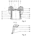
- FIG. 5 shows a further embodiment of the invention.
- the fuse housing is formed by a pot-like insulating part 50 with a pot base 51, in which two approximately L-shaped contact elements 52 and 53 arranged opposite one another are inserted.
- FIG. 6 shows such a contact element 52. It has a first leg 54, which has a bore 55, and a second leg 56, which is bent slightly outwards approximately in its center at a kink line 57, that is to say counter to the direction of the leg 54 . At the free end there is a nose 58 which projects radially outwards.
- This contact piece or contact element is inserted into the interior of the insulating part 50 in such a way that the bore 55 receives a pin 59 formed on the bottom 51 of the insulating part 50.
- the electrically conductive contact piece 52 is fastened to the insulating part 50 by plastic deformation of this pin, which passes through the bore 55.
- the insulating part 50 has at its end opposite the bottom diametrically opposite slots 60 and 61, the circumferential dimensions of which correspond to the width of the leg 56, so that the area between the kink 57 and the free end of the leg 56 fits through this slot, so that the nose 58 projects beyond the outer surface of the cylindrical section 62 of the insulating part 50, so that there two opposing lugs are formed which can be inserted like a bayonet lock into a corresponding receiving space on a base for receiving the securing element.
- the leg 56 is guided in the circumferential direction by side edges of the slots 60 and 61.
- a circular depression is formed in the outer surface of the bottom 51 of the insulating body 50, so that an area 64 with a relatively thin wall thickness is formed, the diameter of which corresponds to the diameter of the securing plate, so that the securing plate is visible from the outside.
- the nose 59 and the bore 55 must of course be dimensioned such that the electrically conductive contact piece 16 of the fuse 17 always abuts the legs 54. Accordingly, the bore 55 and thus also the nose or the projection 59 must be arranged relatively far outward, as seen from the center line.
- the leg 56 is adapted to the inner surface of the cylindrical wall region 62 of the insulating part 50, so that it is convexly curved outwards. But this does not have to be the case; if the two contact pieces 52 and 53 are narrower, then the legs 56 can also be flat in themselves.
- the head 11 and the insulating parts 30 and 50 On the outer surface - diametrically opposite one another - the head 11 and the insulating parts 30 and 50 have two ears 24 and 25 lying in one plane, which protrude beyond the pot bases 11, 31 and 51 in the axial direction, in the axial direction essentially over the whole Length of the wall 12 of the head 10 and the insulating parts 30 and 50 extend and protrude radially, so that two handles are formed with which the head 10 and the insulating parts 30 and 50 and thus the metal sleeve 13 and the sleeve 32 and the contact pieces 52 and 53 can be rotated.
- the side surfaces of the ears 25 and 26 are provided with a corrugation 26 running in the axial direction in order to achieve better handling.
- the material of the head 10 and the insulating parts 30 and 50 is electrically insulating material which is clearly transparent, so that openings which have to be closed with a glass pane are no longer required.
- the head 10 and the insulating parts 30 and 50 essentially from plastic which is not clearly transparent and the base 11, 31 and 51 from clear plastic. The technical possibility for this exists, as required.
Landscapes
- Fuses (AREA)
- Cookers (AREA)
Abstract
Description
- Die Erfindung betrifft ein Sicherungsgehäuse gemäß dem Oberbegriff des Anspruches 1.
- Schmelzsicherungen, die zur Absicherung von elektrischen Leitungsnetzen dienen, sind in aller Regel in einem Gehäuse aufgenommen, das aus einem Kopf aus elektrisch isolierendem Material und einer von dem Kopf teilweise umgebenen Metallhülse gebildet ist. Mittels des Kopfes und der meist mit einem Gewinde versehenen Metallhülse wird die Sicherung in Kontaktierung mit einem in einem Sockel befindlichen Anschlußelement dadurch gebracht, daß man den Kopf mit der Metallhülse und der darin befindlichen Sicherung in den Sockel einschraubt. Der Kopf ist angenähert topfförmig ausgebildet und besitzt in seinem Topfboden eine zentrale Durchgangsöffnung, die mit einer Glasscheibe und einer die Glasscheibe halternden Springfeder verschlossen ist. Die Glasscheibe gestattet einen Einblick ins Innere des Kopfes hin zu dem Sicherungsplättchen an der Stirnseite der Sicherung, damit man erkennen kann, ob die Sicherung geschmolzen ist oder nicht. Der Kopf hat damit drei Teile.
- Aufgabe der Erfindung ist es, Sicherungsgehäuse der eingangs genannten Art zu schaffen, der vereinfacht aufgebaut und vereinfacht montierbar ist.
- Diese Aufgabe wird erfindungsgemäß dadurch gelöst durch die kennzeichnenden Merkmale des Anspruches 1.
- Damit kann man die Springfeder und die Glasscheibe einsparen, so daß die Herstellung und die Lagerhaltung eines solchen Kopfes erheblich vereinfacht sind.
- In besonders vorteilhafter Ausgestaltung kann der Topfboden mindestens in einem zentralen Bereich linsen- oder lupenartig ausgebildet sein, wodurch das Sicherungsplättchen vergrößert sichtbar wird, so daß das Ansprechen der Sicherung leichter beurteilt werden kann.
- Anstatt einer linsen- oder lupenartigen Verdickung kann in einem zentralen Bereich eine gegenüber dem übrigen Bereich des Isolierteils dünnere Wandstärke vorgesehen werden. Dadurch ist auch eine optimale Sicht auf das Sicherungsplättchen erzielt. Wegen eines etwas vereinfachten Werkzeuges kann diese Ausführung mit der dünneren Wandstärke etwas günstiger sein als die Ausführung mit der linsen- oder lupenartigen Verdickung.
- Im Inneren ist der Kopf in weiterer Ausgestaltung der Erfindung mit Rastmitteln versehen, in die Rastmittel an der Hülse zur festen Verbindung von Hülse und Topf eingreifen.
- Eine andere Befestigung des elektrisch leitenden Elementes am Topfboden kann dadurch erfolgen, daß an der Innenseite des Topfbodens wenigstens eine Noppe angeformt ist, die in eine daran angepaßte Öffnung im elektrisch leitenden Element eingreift und darin durch plastische Verformung fixiert ist. Diese Festlegung des elektrisch leitenden Elements innerhalb des Topfes ist insoweit einfacher, als die Herstellung einer Verrastung nicht mehr erforderlich wird. Selbstverständlich könnte die Noppe bzw. könnten Noppen anstatt an der Innenseite des Topfbodens auch an der Innenfläche des zylindrischen Teiles des Sicherungsgehäuses angeformt sein.
- Eine weitere Ausgestaltung der Erfindung, insbesondere der Befestigung des elektrisch leitenden Teiles innerhalb des Isolierteiles kann dahingehen, daß das elektrisch leitende Element mittel sich gegen die Innenfläche der zylindrischen Wandung des Isolierteils anliegender federnder Zungen kraftschlüssig im Isolierteil festgehalten ist. Zu diesem Zweck wird zwecks Montage das elektrisch leitende Teil einfach ins Innere des Isolierteils eingesetzt und ist dann darin quasi festgeklemmt.
- Das elektrisch leitende Teil kann als an sich bekannte Metallhülse ausgebildet sein, die teilweise vom Isolierteil umfaßt ist.
- Es besteht darüberhinaus auch die Möglichkeit, das Isolierteil an seiner Außenfläche mit einem Schraubgewinde zu versehen, so daß das Isolierteil selbst in das Innengewinde des Sockels eingesetzt und eingeschraubt werden kann.
- In diesem Fall wird das elektrisch leitende Element entweder als U-förmig gebogener federnder Streifenleiter ausgebildet sein, dessen Schenkel im Bereich des Schraubgewindes je einen Längsschlitz im Isolierteil durchgreifen und sich außerhalb der durch den Kerndurchmesser des Schraubgewindes gebildeten Hüllzylinderfläche befinden; im Falle einer Hülse können an dem zylindrischen Bereich der Hülse federnde Zungen nach außen ausgestanzt und ausgebogen werden, die in gleicher Weise wie die Schenkel der federnden Streifenleiter je einen Längsschlitz im Isolierteil durchgreifen und sich ebenfalls außerhalb der durch den Kerndurchmesser des Schraubgewindes gebildeten Hüllzylinderfläche befinden. In beiden Fällen, also sowohl beim elektrisch leitenden Streifenleiter als auch bei der Hülse wird mittels der den Kerndurchmesser überragenden Abschnitten beim Einschrauben eine elektrisch leitende Verbindung zu dem Außengewinde am Sockel gebildet.
- Selbstverständlich besteht auch die Möglichkeit, das Isolierteil nicht mit einem Schraubgewinde zu versehen, sondern mittels der in ähnlicher Weise wie bei der Ausführung mit dem Schraubgewinde die Längsschlitze durchgreifenden Fingerelemente eine bajonettverschlußartige Befestigung zu erzielen, wobei an den Fingern entsprechende Vorsprünge vorgesehen sind, die hinter entsprechende Rücksprünge am Sockel greifen.
- Eine weitere vorteilhafte Ausgestaltung der Erfindung kann dahin gehen, daß an der Außenwandung des Kopfes zwei sich diametral gegenüberliegende, in einer durch die Mittelachse des Kopfes hindurchgehenden Ebene angeformt sind. Hierdurch kann der Kopf besser verdreht werden. Bei den bekannten Köpfen ist an der Außenseite eine Art Riffelung mit einigen wenigen Vorsprüngen vorhanden.
- Die erfindungsgemäße Ausgestaltung ist daher im Vergleich zum Stand der Technik schon wegen der geringeren Anzahl an Einzelteilen erheblich einfacher aufgebaut und darüberhinaus auch leichter zu bedienen, und außerdem ist besser erkennbar, ob die Sicherung angesprochen hat oder nicht.
- Anhand der Zeichnung, in der einige Ausführungsbeispiele der Erfindung dargestellt sind, sollen weitere vorteilhafte Ausgestaltungen und Verbesserungen der Erfindung näher erläutert und beschrieben werden.
- Es zeigen:
- Figur 1 eine Ansicht einer ersten Ausgestaltung eines Sicherungsgehäuses von unten,
- Figur 2 eine Schnittansicht gemäß Schnittlinie II-II der Figur 1,
- Figur 3 eine Aufsicht von oben auf den Kopf,
- Figur 4 eine Schnittansicht durch eine weitere Ausführungsform der Erfindung,
- Figur 5 eine dritte Ausführungsform der Erfindung und
- Figur 6 eine perspektivische Ansicht eines elektrisch leitenden Elements für das Sicherungsgehäuse gemäß Figur 5.
- Es sei Bezug genommen auf die Figur 2. Dort ist ein Kopf 10 dargestellt, der einen napf- oder topfförmigen Querschnitt aufweist, mit einem Napfboden 11 und einer Napfwand 12. Mit der Napfwand 12 umfaßt der Kopf 10 teilweise eine Metallhülse 13, die im Bereich der Innenfläche des Napfbodens 11 ebenfalls einen Boden 14 aufweist, der mit einem Anschlußkontaktstück 16 an einer strichliert dargestellten, ins Innere der Metallhülse 13 und damit des Kopfes 10 eingreifenden Schmelzsicherung 17 kontaktiert. Im Bode 14 der Metallhülse 13 ist eine Zentralbohrung 15 eingebracht, deren Innendurchmesser dem Durchmesser des Sicherungsplättchens der Schmelzsicherung 17 entspricht. Die Metallhülse 13 besitzt an ihrem dem Topfboden 11 entgegengesetzten Ende auf ihrer Außenfläche Nasen 18 und 19, mit denen die Metallhülse 17 bajonettverschlußartig in eine nicht näher dargestellte Ausnehmung an einem Sockel, in den die Sicherung 17 eingesetzt werden soll, eingreifen können. An der Innenfläche des Topfbodens 11 im zentralen Bereich befindet sich eine Vertiefung 20 und an der Außenfläche des Topfbodens 11 im Bereich der Vertiefung 20 ist der Topfboden mit einer linsenartigen Vorwölbung 21 versehen, wodurch sich eine lupenartige Form im mittleren (zentralen) Bereich des Topfbodens 11 bildet.
- Die Zentralbohrung 15 entspricht außerdem dem Durchmesser der Vertiefung, so daß die Vertiefung 20 mit der linsenartigen Vorwölbung 21 und die Zentralbohrung 15 miteinander fluchten.
- An der Innenfläche des Napfbodens oder Topfbodens 11 sind zwei Vorsprünge 22 und 23 angeformt, die eine langgestreckte Form aufweisen. In dem Boden 14 der Metallhülse 14 sind entsprechend ausgebildete Langlöcher 26 und 27 eingebracht, die symmetrisch zu der Zentralbohrung 15 angeordnet sind, so daß die Vorsprünge 22 und 23 im montierten Zustand die Langlöcher 26 und 27 durchgreifen. Nach der Montage werden die Vorsprünge 22 und 23 plastisch verformt, so daß die Metallhülse im Inneren des Kopfes 12 fixiert ist.
- An der Innenfläche des Topfbodens 11 können auch Rastelemente vorgesehen sein, hinter die nicht mehr dargestellte, entsprechende Rastelemente an der Metallhülse 13 zur formschlüssigen Verbindung zwischen Kopf 10 und Metallhülse 13 eingreifen.
- Es sei nun Bezug genommen auf die Figur 4. Das Sicherungsgehäuse besteht aus einem topfförmigen Isolierteil 30, welches einen Topfboden 31 aufweist, der eine Metallhülse 32 aufnimmt. Das Isolierteil 30 umfaßt die Metallhülse 32 vollständig. Sie besitzt an ihrem dem Topfboden 31 entgegengesetzten Endbereich einen Außengewindeabschnitt 34, dessen Gewindegänge so ausgebildet sind, daß sie in ein Innengewinde an einem Sockel zur Aufnahme einer Schmelzsicherung eingesetzt bzw. eingeschraubt werden können. Im Gewindeabschnitt 34 besitzt das Isolierteil 30 je einen Längsschlitz 35 und 36, welche Längsschlitze 35 und 36 sich diametral gegenüberliegend angeordnet sind. Selbstverständlich besteht auch die Möglichkeit, mehr als zwei Längsschlitze vorzusehen; diese müßten dann lediglich gleichmäßig am Umfang verteilt in das Isolierteil 30 eingebracht werden. Die Metallhülse 32 ist ähnlich wie das Isolierteil 30 mit einem Boden 33 versehen, der eine Zentralbohrung 34 aufweist, deren Durchmesser dem Durchmesser der Zentralbohrung 15 der Figur 2 entspricht. An dem dem Boden 33 entgegengesetzten Ende im Bereich der Schlitze 35 und 36 besitzt die Hülse nach außen ausgebogene Kontaktfinger 37 und 38, die zu ihrem freien Ende wieder zurückgebogen sind, so daß die Kontaktfinger 37 und 38 eine Art Kontaktbauch bilden, wobei der maximale Durchmesser etwa dem Außendurchmesser des Gewindeabschnittes entspricht. In jedem Fall muß der maximale Durchmesser der beiden Kontaktfinger 37 und 38 deutlich größer sein als der Kerndurchmesser des Gewindeabschnittes 34.
- Im übrigen ist das Isolierteil 30 gleich dem Kopf 10, wobei mit gleichen Bezugsziffern für gleichwirkende Elemente die Gleichheit betont wird.
- Das Isolierteil 30 besteht in seiner Gesamtheit aus klar durchsichtigem Material, in das die Metallhülse in gleicher Weise wie bei der Ausführung nach den Figuren 1 und 2 eingesetzt ist. Selbstverständlich bestünde auch die Möglichkeit bei der Ausführung nach Figur 2, die Metallhülse 13 in den Kopf 10 einzuspritzen, so daß eine Spritzverbindung zwischen den beiden Teilen erzielt ist.
- Die Figur 5 zeigt eine weitere Ausgestaltung der Erfindung. Das Sicherungsgehäuse ist gebildet durch ein topfartiges Isolierteil 50 mit einem Topfboden 51, in den zwei sich gegenüberliegend angeordnete etwa L-förmige Kontaktelemente 52 und 53 eingesetzt sind.
- Die Figur 6 zeigt ein derartiges Kontaktelement 52. Es besitzt einen ersten Schenkel 54, der eine Bohrung 55 aufweist, sowie einen zweiten Schenkel 56, der etwa in seiner Mitte bei einer Knicklinie 57 leicht nach außen, also entgegen der Richtung des Schenkels 54 aufgebogen ist. Am freien Ende befindet sich eine Nase 58, die radial nach außen vorspringt.
- Dieses Kontaktstück oder Kontaktelement wird ins Innere des Isolierteils 50 eingesetzt und zwar derart, daß die Bohrung 55 einen am Boden 51 des Isolierteils 50 angeformten Zapfen 59 aufnimmt. Durch plastische Verformung dieses Zapfens, welcher die Bohrung 55 durchgreift, wird das elektrisch leitende Kontaktstück 52 am Isolierteil 50 befestigt. Das Isolierteil 50 besitzt an seinem dem Boden entgegengesetzt liegenden Ende sich diametral gegenüberliegende Schlitze 60 und 61, deren Umfangsabmessungen der Breite des Schenkels 56 entsprechen, so daß der Bereich zwischen der Abknickung 57 und dem freien Ende des Schenkels 56 durch diesen Schlitz hindurchpaßt, so daß die Nase 58 die Außenfläche des zylindrischen Abschnittes 62 des Isolierteils 50 überragt, so daß dort zwei sich gegenüberliegende Nasen gebildet sind, die bajonettverschlußartig in einen entsprechenden Aufnahmeraum an einem Sockel zur Aufnahme des Sicherungselementes eingesetzt werden können. Die Führung des Schenkels 56 in Umfangsrichtung erfolgt durch Seitenkanten der Schlitze 60 und 61.
- Die freien Enden der Schenkel 54 der beiden elektrisch leitenden Kontaktstücke 52 und 53 enden in einem solchen Abstand voneinander, daß in jedem Fall das Sicherungsplättchen der strichliert dargestellten Sicherung 17 frei bleibt. In der Außenfläche des Bodens 51 des Isolierkörpers 50 ist eine kreisförmige Vertiefung eingeformt, so daß ein Bereich 64 mit relativ dünner Wandstärke gebildet ist, dessen Durchmesser dem Durchmesser des Sicherungsplättchens entspricht, so daß das Sicherungsplättchen von außen sichtbar ist.
- Nachzutragen ist noch, daß natürlich die Nase 59 und die Bohrung 55 so bemessen sein müssen, daß das elektrisch leitende Kontaktstück 16 der Sicherung 17 immer an den Schenkeln 54 anliegt. Demgemäß muß die Bohrung 55 und damit auch die Nase bzw. der Vorsprung 59 relativ weit außen, von der Mittellinie aus gesehen, angeordnet sein.
- Der Schenkel 56 ist, wie aus Figur 6 ersichtlich, der Innenfläche des zylindrischen Wandbereiches 62 des Isolierteils 50 angepaßt, so daß er nach außen konvex gebogen ist. Dies muß aber nicht sein; wenn die beiden Kontaktstücke 52 und 53 schmaler ausgebildet sind, dann können die Schenkel 56 auch in sich flach ausgebildet sein.
- An der Außenfläche - sich diametral gegenüberliegend - besitzen der Kopf 11 und die Isolierteile 30 und 50 zwei in einer Ebene liegende Ohren 24 und 25, die die Topfböden 11, 31 und 51 in axialer Richtung überragen, in axialer Richtung weiterhin im wesentlichen über die gesamte Länge der Wandung 12 des Kopfes 10 und der Isolierteile 30 und 50 verlaufen und radial vorstehen, so daß zwei Handgriffe gebildet sind, mit denen der Kopf 10 und die Isolierteile 30 und 50 und damit die Metallhülse 13 sowie die Hulse 32 und die Kontaktstücke 52 und 53 verdreht werden können. Die Seitenflächen der Ohren 25 und 26 sind mit einer in achsialer Richtung verlaufenden Riffelung 26 versehen, um eine bessere Handhabbarkeit zu erzielen. Das Material des Kopfes 10 und der Isolierteile 30 une 50 ist elektrisch isolierendes Material, welches klar durchsichtig ist, so daß Durchbrüche, die mit einer Glasscheibe verschlossen werden müssen, nicht mehr erforderlich sind. Es besteht natürlich auch die Möglichkeit, den Kopf 10 und die Isolierteile 30 und 50 im wesentlichen aus nicht klar durchsichtigem Kunststoff und den Boden 11, 31 und 51 aus klar durchsichtigem Kunststoff herzustellen. Die technische Möglichkeit hierzu besteht, nach Bedarf.
- Selbstverständlich können noch viele Ausführungen in den Schutzumfang der Erfindung fallen, insbesondere solche Ausführungen, bei denen andere elektrisch leitende Teile in ein Isolierteil aus klar durchsichtigem Kunststoff eingesetzt sind. Beispielsweise könnte anstatt zweier L-förmiger Kontaktstücke wie die Kontaktstücke 52 und 53 auch ein U-förmiges Teil eingesetzt werden. Darüberhinaus könnte die Hülse in der in Figur 2 dargestellten Weise ausgebildet sein, allerdings ohne Boden 14, und anstatt des Bodens 14 sind lediglich zwei oder drei ra dial nach innen vorstehende Kontaktfahnen vorgesehen. Auch besteht die Möglichkeit, die Fixierung der Hülse 13 so vorzunehmen, daß ein aufgespreizter Finger sich an der Innenfläche des Isolierteiles, beispielsweise des Isolierteiles 50 verhakt. Auch könnte das Isolierteil nur im Bereich des Bodens aus klar durchsichtigem Material bestehen, im übrigen Bereich aber aus undurchsichtigem.
Claims (6)
Applications Claiming Priority (4)
| Application Number | Priority Date | Filing Date | Title |
|---|---|---|---|
| DE19893934048 DE3934048C2 (de) | 1989-10-12 | 1989-10-12 | Sicherungsgehäuse |
| DE3934048 | 1989-10-12 | ||
| DE3940754 | 1989-12-09 | ||
| DE19893940754 DE3940754C2 (de) | 1989-10-12 | 1989-12-09 | Sicherungsgehäuse |
Publications (3)
| Publication Number | Publication Date |
|---|---|
| EP0423578A2 true EP0423578A2 (de) | 1991-04-24 |
| EP0423578A3 EP0423578A3 (en) | 1992-04-22 |
| EP0423578B1 EP0423578B1 (de) | 1995-08-30 |
Family
ID=25886031
Family Applications (1)
| Application Number | Title | Priority Date | Filing Date |
|---|---|---|---|
| EP19900119230 Expired - Lifetime EP0423578B1 (de) | 1989-10-12 | 1990-10-06 | Sicherungsgehäuse |
Country Status (3)
| Country | Link |
|---|---|
| EP (1) | EP0423578B1 (de) |
| DE (3) | DE3934048C2 (de) |
| DK (1) | DK0423578T3 (de) |
Families Citing this family (2)
| Publication number | Priority date | Publication date | Assignee | Title |
|---|---|---|---|---|
| EP1464544B1 (de) | 2003-04-03 | 2010-09-15 | Delphi Technologies, Inc. | Gehäuse mit Stromleiterschiene für eine Trennvorrichtung |
| DE102004011863A1 (de) * | 2003-04-03 | 2004-10-14 | Dynamit Nobel Ais Gmbh Automotive Ignition Systems | Gehäuse mit Stromleiterschiene für ein Trennsystem |
Family Cites Families (13)
| Publication number | Priority date | Publication date | Assignee | Title |
|---|---|---|---|---|
| DE1987221U (de) * | 1968-06-12 | Robert Schmidt K.G., 5956 Grevenbrück | Schraubkappe zur lösbaren Halterung eines Schmelzeinsatzes im Sockel einer elektrischen Sicherung | |
| DE700927C (de) * | 1938-12-24 | 1941-01-04 | Siemens Schuckertwerke Akt Ges | Verfahren zur Herstellung eines aus einem durchsic B. Glas, bestehenden Stoepselkopfes |
| US2386060A (en) * | 1942-10-29 | 1945-10-02 | Gen Electric | Fuse unit |
| AT163794B (de) * | 1948-05-14 | 1949-08-10 | Wolfgang Pluskal | Stöpselkopf für Patronensicherungen |
| DE958405C (de) * | 1954-01-16 | 1957-02-21 | Standard Elek K Ag | Sicherungshalter fuer Kennmeldersicherungen |
| DE1000914B (de) * | 1954-03-11 | 1957-01-17 | Efen Elektrotech Fab | Einbau- oder Aufbausicherungselement |
| DE1299757B (de) * | 1965-07-15 | 1969-07-24 | Siemens Ag | Schraubkappe fuer D-Sicherungssockel |
| DE1563585A1 (de) * | 1966-12-20 | 1970-05-27 | Aloys Mennekes Fa | Schraubkappe fuer Sicherungselemente |
| DE1588940C3 (de) * | 1967-03-29 | 1974-06-27 | Wickmann-Werke Ag, 5810 Witten | Sicherungshalter |
| DE2033529A1 (de) * | 1970-07-07 | 1972-01-20 | Gruener E | Schraubkappe S |
| DE2648670A1 (de) * | 1976-10-27 | 1978-05-03 | Geyer Gmbh & Co Christian | Sicherungs-lastschalter |
| DE8303747U1 (de) * | 1983-02-10 | 1984-04-26 | Siemens AG, 1000 Berlin und 8000 München | Schraubkappe für elektrische Schraubsicherungen |
| SU1621099A1 (ru) * | 1988-10-31 | 1991-01-15 | Всесоюзный научно-исследовательский, проектно-конструкторский и технологический институт низковольтного аппаратостроения | Плавкий предохранитель |
-
1989
- 1989-10-12 DE DE19893934048 patent/DE3934048C2/de not_active Expired - Fee Related
- 1989-12-09 DE DE19893940754 patent/DE3940754C2/de not_active Expired - Fee Related
-
1990
- 1990-10-06 DK DK90119230T patent/DK0423578T3/da active
- 1990-10-06 EP EP19900119230 patent/EP0423578B1/de not_active Expired - Lifetime
- 1990-10-06 DE DE59009575T patent/DE59009575D1/de not_active Expired - Fee Related
Also Published As
| Publication number | Publication date |
|---|---|
| DE3934048A1 (de) | 1991-04-25 |
| DE3940754C2 (de) | 1995-04-13 |
| EP0423578B1 (de) | 1995-08-30 |
| DE3940754A1 (de) | 1991-06-27 |
| DE3934048C2 (de) | 1995-07-13 |
| DK0423578T3 (da) | 1995-12-18 |
| EP0423578A3 (en) | 1992-04-22 |
| DE59009575D1 (de) | 1995-10-05 |
Similar Documents
| Publication | Publication Date | Title |
|---|---|---|
| EP1275173B1 (de) | Stecker mit einer hülse | |
| DE2262345A1 (de) | Lampenfassungseinrichtung | |
| DE3912189A1 (de) | Schutzleiterverbindung | |
| EP0199119B1 (de) | Elektromagnetisches Relais | |
| DE4428699B4 (de) | Elektrische Verbindungsanordnung | |
| DE1934795A1 (de) | Schutzrohrankerkontakt | |
| DE3816909C2 (de) | ||
| EP0423578B1 (de) | Sicherungsgehäuse | |
| EP0660459B1 (de) | Vielfach-Flachstecker | |
| DE69015243T2 (de) | Anschlussvorrichtung. | |
| DE2618317C2 (de) | Adapter zur Verbindung elektromagnetischer Schaltgeräte mit gedruckten Leiterplatten | |
| DE3408432A1 (de) | Fuer eine elektrische steckkontaktvorrichtung vorgesehenes kontaktstueck | |
| DE4031167C2 (de) | Elektrische Leuchte | |
| DE3014495C2 (de) | ||
| DE2947474C2 (de) | ||
| DE3031800C2 (de) | Elastisches Kontaktglied einer Buchse für einen Stiftstecker | |
| DE102016107818B4 (de) | Drosselanordnung mit einem Einsatz | |
| AT393185B (de) | Lampenfassung | |
| EP0418496A1 (de) | Elektrisches Installationsgerät, insbesondere Schutzkontaktsteckdose | |
| DE4120754C2 (de) | ||
| DE3643593C3 (de) | Elektrische Schraubklemme | |
| DE2852418C2 (de) | Kunststoff-Meßwerkträgerrahmen | |
| EP0176843B1 (de) | Passstück für ein elektrisches Installationsgerät | |
| DE69203285T2 (de) | Zum Gebrauch als Einsatz in eine Stromschiene vorgesehene Kontaktvorrichtung. | |
| DE69107049T2 (de) | Befestigungssockel für eine Antenne, insbesondere für eine Teleskopantenne. |
Legal Events
| Date | Code | Title | Description |
|---|---|---|---|
| PUAI | Public reference made under article 153(3) epc to a published international application that has entered the european phase |
Free format text: ORIGINAL CODE: 0009012 |
|
| AK | Designated contracting states |
Kind code of ref document: A2 Designated state(s): CH DE DK LI NL SE |
|
| PUAL | Search report despatched |
Free format text: ORIGINAL CODE: 0009013 |
|
| AK | Designated contracting states |
Kind code of ref document: A3 Designated state(s): CH DE DK LI NL SE |
|
| 17P | Request for examination filed |
Effective date: 19920826 |
|
| 17Q | First examination report despatched |
Effective date: 19940422 |
|
| GRAA | (expected) grant |
Free format text: ORIGINAL CODE: 0009210 |
|
| AK | Designated contracting states |
Kind code of ref document: B1 Designated state(s): CH DE DK LI NL SE |
|
| REF | Corresponds to: |
Ref document number: 59009575 Country of ref document: DE Date of ref document: 19951005 |
|
| REG | Reference to a national code |
Ref country code: DK Ref legal event code: T3 |
|
| PLBE | No opposition filed within time limit |
Free format text: ORIGINAL CODE: 0009261 |
|
| STAA | Information on the status of an ep patent application or granted ep patent |
Free format text: STATUS: NO OPPOSITION FILED WITHIN TIME LIMIT |
|
| 26N | No opposition filed | ||
| NLS | Nl: assignments of ep-patents |
Owner name: ABB COMPONENTEN B.V. |
|
| PGFP | Annual fee paid to national office [announced via postgrant information from national office to epo] |
Ref country code: DK Payment date: 20030808 Year of fee payment: 14 |
|
| PGFP | Annual fee paid to national office [announced via postgrant information from national office to epo] |
Ref country code: DE Payment date: 20030908 Year of fee payment: 14 |
|
| PGFP | Annual fee paid to national office [announced via postgrant information from national office to epo] |
Ref country code: CH Payment date: 20030909 Year of fee payment: 14 |
|
| PGFP | Annual fee paid to national office [announced via postgrant information from national office to epo] |
Ref country code: SE Payment date: 20030912 Year of fee payment: 14 |
|
| PG25 | Lapsed in a contracting state [announced via postgrant information from national office to epo] |
Ref country code: SE Free format text: LAPSE BECAUSE OF NON-PAYMENT OF DUE FEES Effective date: 20041007 |
|
| PG25 | Lapsed in a contracting state [announced via postgrant information from national office to epo] |
Ref country code: LI Free format text: LAPSE BECAUSE OF NON-PAYMENT OF DUE FEES Effective date: 20041031 Ref country code: CH Free format text: LAPSE BECAUSE OF NON-PAYMENT OF DUE FEES Effective date: 20041031 |
|
| PG25 | Lapsed in a contracting state [announced via postgrant information from national office to epo] |
Ref country code: DK Free format text: LAPSE BECAUSE OF NON-PAYMENT OF DUE FEES Effective date: 20041101 |
|
| PG25 | Lapsed in a contracting state [announced via postgrant information from national office to epo] |
Ref country code: DE Free format text: LAPSE BECAUSE OF NON-PAYMENT OF DUE FEES Effective date: 20050503 |
|
| EUG | Se: european patent has lapsed | ||
| REG | Reference to a national code |
Ref country code: DK Ref legal event code: EBP |
|
| REG | Reference to a national code |
Ref country code: CH Ref legal event code: PL |
|
| PGFP | Annual fee paid to national office [announced via postgrant information from national office to epo] |
Ref country code: NL Payment date: 20091016 Year of fee payment: 20 |
|
| REG | Reference to a national code |
Ref country code: NL Ref legal event code: V4 Effective date: 20101006 |
|
| PG25 | Lapsed in a contracting state [announced via postgrant information from national office to epo] |
Ref country code: NL Free format text: LAPSE BECAUSE OF EXPIRATION OF PROTECTION Effective date: 20101006 |