EP0423652A2 - Appareil vidéo pour deux sources de programme vidéo - Google Patents
Appareil vidéo pour deux sources de programme vidéo Download PDFInfo
- Publication number
- EP0423652A2 EP0423652A2 EP90119632A EP90119632A EP0423652A2 EP 0423652 A2 EP0423652 A2 EP 0423652A2 EP 90119632 A EP90119632 A EP 90119632A EP 90119632 A EP90119632 A EP 90119632A EP 0423652 A2 EP0423652 A2 EP 0423652A2
- Authority
- EP
- European Patent Office
- Prior art keywords
- television program
- video
- program source
- field
- recording
- Prior art date
- Legal status (The legal status is an assumption and is not a legal conclusion. Google has not performed a legal analysis and makes no representation as to the accuracy of the status listed.)
- Withdrawn
Links
Images

Classifications
-
- H—ELECTRICITY
- H04—ELECTRIC COMMUNICATION TECHNIQUE
- H04N—PICTORIAL COMMUNICATION, e.g. TELEVISION
- H04N9/00—Details of colour television systems
- H04N9/79—Processing of colour television signals in connection with recording
- H04N9/80—Transformation of the television signal for recording, e.g. modulation, frequency changing; Inverse transformation for playback
- H04N9/802—Transformation of the television signal for recording, e.g. modulation, frequency changing; Inverse transformation for playback involving processing of the sound signal
-
- H—ELECTRICITY
- H04—ELECTRIC COMMUNICATION TECHNIQUE
- H04N—PICTORIAL COMMUNICATION, e.g. TELEVISION
- H04N5/00—Details of television systems
- H04N5/76—Television signal recording
- H04N5/91—Television signal processing therefor
- H04N5/92—Transformation of the television signal for recording, e.g. modulation, frequency changing; Inverse transformation for playback
- H04N5/9201—Transformation of the television signal for recording, e.g. modulation, frequency changing; Inverse transformation for playback involving the multiplexing of an additional signal and the video signal
- H04N5/9205—Transformation of the television signal for recording, e.g. modulation, frequency changing; Inverse transformation for playback involving the multiplexing of an additional signal and the video signal the additional signal being at least another television signal
Definitions
- the invention relates to video devices according to the preambles of claims 1 and 9.
- video devices which can record and reproduce a television program source, ie an image source and a plurality of audio channels, on magnetic tapes.
- a television program source ie an image source and a plurality of audio channels
- video devices work with 50 or 60 fields per second and have their own reception and demodulation device in order to be able to record television program programs even when none TV receiver or its reception and demodulation device is available.
- the picture and sound signal in the underlying TV standard ie again with 50 or 60 fields per second, are fed to a television or monitor.
- the invention has for its object to develop a video device according to the preamble of claim 1 such that two television program sources can be recorded simultaneously on a recording medium without significant loss of picture quality.
- the invention has for its object to develop a video device according to the preamble of claim 9 such that two television program sources recorded with a video device according to claim 1 can be reproduced individually without loss of picture quality.
- two television program sources can be recorded simultaneously without the need for two video devices or two recording media.
- recording material is no longer required for recording two television program sources, as was previously the case for recording one television program source.
- one of the two television program sources can optionally be reproduced.
- both television program sources can be reproduced simultaneously on different monitors or television sets.
- the invention makes use of the knowledge that the eye is relatively insensitive to vertical loss of resolution.
- the viewer of a television picture consisting of two successive fields with a total of 625 lines, one field forming the odd lines and one field forming the even lines, can therefore not see any horizontal loss of resolution if the television picture is formed from two identical fields.
- the image quality of the recording is reduced only to the image quality of a feature film.
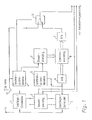
- FIG. 1 shows a block diagram of a recording device for a video device according to the invention.
- the antenna connector 11 of the receiver / demodulator 1, the connector for external video sources, such as. B. a video camera, the switch 12 and the recording device not shown below correspond to the structure of a video device according to the prior art.
- a receiver / demodulator 2 For the recording method according to the invention for recording two video channels on a tape, each of which has an image and a mono or stereo sound source, a receiver / demodulator 2, a field memory 6, 8, 9, two synchronization detectors 4, 6, a switching device 10, a control device 7, and a tone selection device 3 is required.
- the field memory is composed of an A / D converter 6, a D / A converter 9 and a digital storage device 8.
- the inputs of the receiver / demodulators 1, 2, which can be individually tuned, are connected to the same antenna connection 11. Signals appear at their outputs like they 3A and 3B. These signals have 50 or 60 fields per second. A vertical pulse occurs in each vertical blanking interval between two fields and, depending on the TV standard, a large number of line synchronizing pulses occur during a field. The vertical pulses and the line synchronizing pulses are not shown in FIG. 3.
- the signal according to FIG. 3A is fed to the synchronization detector 4 and the switching device 10, the signal according to FIG. 3B to the synchronization detector 5 and the A / D converter 6 of the field memory.
- the synchronization detectors 4, 5 pass on the vertical and line synchronization pulses of the two television program sources to the control device 7 of the field memory 6, 8, 9.
- the field characteristic pulses of the first television program source are also forwarded to the switching device 10 by the synchronization detector 4.
- the storage device 6, 8, 9 can store a complete field.
- the analog field is converted by the memory device 6, 8, 9 by means of the analog / digital converter 6 analog / digital, and after the memory device 8 by means of the digital / analog converter 9 again converted digital / analog.
- the control device 7 feeds the storage device 8 after each vertical pulse in the signal according to FIG. 3B write pulses corresponding to the line synchronizing pulses in the signal according to FIG. 3B and after each vertical pulse according to FIG. 3A read or output pulses corresponding to the line synchronizing pulses in the signal according to FIG. 3A.
- This causes every second field of the second video channel to be in the field cher 6, 8, 9 stored and simultaneously passed to the switching device 10 with each field of the first television program source.
- the switching device 10 is controlled in this way by means of the vertical pulses of the first television program source. That it inserts a field of the second television program source in the signal of FIG. 3B instead of every second field of the first television program source. This results in the signal curve according to FIG. 3C at the output of the switching device 10.
- This signal which has the same vertical and line synchronizing pulses as the signal according to FIG. 3A or 3B, is passed on to the recording device of the video device and recorded.
- the switching device 10 can be equipped with clamping stages for each input channel. If the user of the video device wants to record only one television program source, the switching device 10 can be kept constantly in the upper position according to FIG. 1.
- the sound selection device 3 is supplied by the receiver / demodulator 1, 2 with the respective sound signal from the television image source 1 and 2, which in each case consists of two channels.
- the sound channels of the first television program source are passed on to the subsequent recording device by means of the tone selection device 3.
- the tone selection device 3 When recording two television program sources, only one sound channel of a television program source is switched through from the sound channels of the two television program sources by means of the tone selection device 3 to the subsequent recording device.
- the user of the video device can use an input device, not shown, to set the tone dialing device 3 in such a way that that this passes on the desired sound channels.
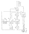
- Fig. 2 shows a block diagram of a playback device for a video device according to the invention. 3C and is applied to the inputs of an A / D converter 53 and a synchronization detector 52 and to a first input of the switching device 56. Furthermore, the audio signal consisting of two channels is applied to the audio selection device 55.
- the field memory 51, 53, 54 of the reproducing device is constructed like the field memory 6, 8, 9 of the recording device, i. H. that the fields to be stored are converted analog / digital / analog and the digital memory has at least the capacity corresponding to one field.
- the signal according to FIG. 3C again contains vertical and line synchronizing pulses, not shown, like the signals from FIGS. 3A and 3B.
- the synchronization detector 52 supplies the vertical and line synchronization pulses to the control device 50.
- a selection device 57 By means of a selection device 57, the user can set whether a first or a second television program source recorded with a recording device according to FIG. 1 or a television program source recorded with a standard method is to be reproduced.
- the selection device 57 sets the control device 50 in accordance with the desired operating mode. If standard reproduction is to be carried out, the control device 50 controls the changeover device 56 in such a way that the changeover switch is constantly held in the upper position according to FIG. 2.
- the control device 50 controls the storage device 51 in accordance with the vertical and line synchronization signals of the signal according to FIG. 3C in such a way that every second field is stored from the signal according to FIG. 3C. Since the fields of the first and second channels alternate, either all recorded fields of the first or second television program source are therefore stored in accordance with the setting of the selector 57, the fields of the television program source to be reproduced being stored in the device according to the invention.
- the field memory 51, 53, 54 is then read out in accordance with the vertical and line synchronization signals of the signal according to FIG. 3C. i.e. the stored field of the television program source to be reproduced is then applied to the second input of the switching device 56 when the field of the television program source not to be reproduced is present at the first input of the switching device 56.
- the switching device 56 is controlled by the control device 50 in accordance with the vertical pulses in such a way that it stores the fields of the television program source to be played back first in accordance with the upstream playback device and then the same field as it came from the playback device in the field memory 51, 53, 54, switches through.
- a sequence of fields according to FIG. 3D or FIG. 3E, which has 50 or 60 fields per second, thus arises at the output of the switching device 56, two successive fields being identical.
- the output signal of the switching device 50 according to FIG. 3D or 3E and the output signal of the tone selection device 55 are an output device such. B. an impedance converter circuit or an output socket.
- the sound selection device 55 is controlled by the control device 50 in such a way that it switches through both sound channels during a standard reproduction and through the sound channel associated with the reproduced television program source during a reproduction by means of the reproduction device according to the invention.
- the recording device and the playback device according to the invention can be used in a video recorder, an optical disc player or another video device for video recording or video playback if this device has two audio channels for stereo audio playback in standard operation. Furthermore, in the case of video devices which can record and / or reproduce a plurality of sound channels, a plurality of sound channels of each television picture source can of course be recorded.
- the recording device and the playback device according to the invention are arranged in a video device, the field memory, the switching device, the tone dialing device and the synchronization detectors can be used both for the recording device according to the invention and for the playback device according to the invention with suitable connection of the individual components.
- the two television program sources recorded simultaneously could also be reproduced simultaneously on two different monitors or two different monitor groups (hotel TV).
- the storage device of the playback device would have to be controlled in such a way that it successively stores the fields of both Stores video channels and the switching device is equipped with two toggle switches.
- the video device according to the second exemplary embodiment could also have two playback devices according to the invention according to FIG. 2 for this purpose.
- the switching device or the entire reproduction device could also be shifted into the monitors.
- the choice between the two video channels can only be made on the monitor.
- the recording device and the playback device according to the invention could also be used in a television transmission between the transmitter and receiver.
- the transmitter would have to work according to the principle shown in FIG. 1 and the receiver according to the principle shown in FIG. 2.
- the transmission effort and the transmission costs could then be reduced accordingly.
- Video device for recording a first and a second television program source on a recording medium, with a recording device for recording a television program source on a recording medium and with a recording device which alternately supplies the recording device with a field of the first and a field of the second television program source and continuously a sound channel of each television program source ( Fig. 1).
Landscapes
- Engineering & Computer Science (AREA)
- Multimedia (AREA)
- Signal Processing (AREA)
- Television Signal Processing For Recording (AREA)
Applications Claiming Priority (2)
| Application Number | Priority Date | Filing Date | Title |
|---|---|---|---|
| DE3934635 | 1989-10-17 | ||
| DE19893934635 DE3934635C1 (fr) | 1989-10-17 | 1989-10-17 |
Publications (2)
| Publication Number | Publication Date |
|---|---|
| EP0423652A2 true EP0423652A2 (fr) | 1991-04-24 |
| EP0423652A3 EP0423652A3 (en) | 1992-06-17 |
Family
ID=6391649
Family Applications (1)
| Application Number | Title | Priority Date | Filing Date |
|---|---|---|---|
| EP19900119632 Withdrawn EP0423652A3 (en) | 1989-10-17 | 1990-10-12 | Video device for two television programme sources |
Country Status (3)
| Country | Link |
|---|---|
| EP (1) | EP0423652A3 (fr) |
| JP (1) | JPH03208481A (fr) |
| DE (1) | DE3934635C1 (fr) |
Cited By (4)
| Publication number | Priority date | Publication date | Assignee | Title |
|---|---|---|---|---|
| GB2262202A (en) * | 1991-11-26 | 1993-06-09 | Gold Star Co | Recording two video signals onto a single recording medium |
| WO1994016524A1 (fr) * | 1993-01-11 | 1994-07-21 | Bre.In. Brevetti Internazionali S.P.A. | Systeme de composition/decomposition de signaux video pour permettre la transmission/reception et l'enregistrement/lecture simultanes de deux emissions de television |
| FR2713863A1 (fr) * | 1993-12-13 | 1995-06-16 | France Etat Armement | Procédé et dispositif d'enregistrement de l'image vidéo d'au moins deux objets et procédé et dispositif de visualisation de l'image vidéo de ces objets. |
| GB2308257A (en) * | 1994-12-12 | 1997-06-18 | Jacob Ezra | Twin channel video recording |
Families Citing this family (1)
| Publication number | Priority date | Publication date | Assignee | Title |
|---|---|---|---|---|
| KR930009699B1 (ko) * | 1990-09-19 | 1993-10-08 | 삼성전자 주식회사 | 영상 녹/재생 시스템의 더블 기록 재생회로 |
Family Cites Families (16)
| Publication number | Priority date | Publication date | Assignee | Title |
|---|---|---|---|---|
| US3395248A (en) * | 1963-10-19 | 1968-07-30 | Japan Broadcasting Corp | Slow motion reproduction of transversely recorded television signals |
| DE1816041B2 (de) * | 1968-12-20 | 1971-03-25 | Telefunken Patentverwertungsgesell schaft mbH 790OUIm | Magnetbandgeraet zur aufzeichnung und oder wiedergabe von fernsehsignalen |
| US3686436A (en) * | 1969-12-30 | 1972-08-22 | Iit Res Inst | Multiple video signal transducing system and method |
| ATA871375A (de) * | 1975-11-14 | 1976-06-15 | Eumig | System zur speicherung und wiedergabe von fernsehsignalen mehrerer signalquellen |
| JPS5637779A (en) * | 1979-09-05 | 1981-04-11 | Sony Corp | Television picture receiver |
| DE3216320A1 (de) * | 1982-05-03 | 1983-11-10 | Grundig E.M.V. Elektro-Mechanische Versuchsanstalt Max Grundig & Co KG, 8510 Fürth | Verfahren zur aufzeichnung und wiedergabe von fernsehsignalen |
| DE3234846C2 (de) * | 1982-09-21 | 1984-12-13 | Carl Werner 2000 Hamburg Neumann | Videomagnetbandgerät |
| JPS60113301A (ja) * | 1983-11-25 | 1985-06-19 | Victor Co Of Japan Ltd | 記録再生装置 |
| JPH0815332B2 (ja) * | 1985-04-18 | 1996-02-14 | 三菱電機株式会社 | 磁気記録再生装置 |
| DE3744951C2 (en) * | 1986-01-31 | 1992-04-02 | Canon K.K., Tokio/Tokyo, Jp | Magnetic video disc recording and playback system |
| US4774597A (en) * | 1986-07-28 | 1988-09-27 | Eastman Kodak Company | Quadrature head dual channel VCR |
| JPS6339284A (ja) * | 1986-08-04 | 1988-02-19 | Mitsubishi Electric Corp | 磁気記録再生装置 |
| US4758901A (en) * | 1986-10-28 | 1988-07-19 | Eastman Kodak Company | Continuous audio recording in a skip-field video recorder |
| US4847690A (en) * | 1987-02-19 | 1989-07-11 | Isix, Inc. | Interleaved video system, method and apparatus |
| JPS6444688A (en) * | 1987-08-13 | 1989-02-17 | Sharp Kk | Recording and reproducing device |
| US5050010A (en) * | 1987-12-15 | 1991-09-17 | Goldstar Co., Ltd. | Dual video signal simultaneous recording apparatus for a VCR |
-
1989
- 1989-10-17 DE DE19893934635 patent/DE3934635C1/de not_active Revoked
-
1990
- 1990-10-12 EP EP19900119632 patent/EP0423652A3/de not_active Withdrawn
- 1990-10-16 JP JP2277605A patent/JPH03208481A/ja active Pending
Cited By (6)
| Publication number | Priority date | Publication date | Assignee | Title |
|---|---|---|---|---|
| GB2262202A (en) * | 1991-11-26 | 1993-06-09 | Gold Star Co | Recording two video signals onto a single recording medium |
| GB2262202B (en) * | 1991-11-26 | 1995-08-02 | Gold Star Co | Video cassette recorder |
| WO1994016524A1 (fr) * | 1993-01-11 | 1994-07-21 | Bre.In. Brevetti Internazionali S.P.A. | Systeme de composition/decomposition de signaux video pour permettre la transmission/reception et l'enregistrement/lecture simultanes de deux emissions de television |
| FR2713863A1 (fr) * | 1993-12-13 | 1995-06-16 | France Etat Armement | Procédé et dispositif d'enregistrement de l'image vidéo d'au moins deux objets et procédé et dispositif de visualisation de l'image vidéo de ces objets. |
| GB2308257A (en) * | 1994-12-12 | 1997-06-18 | Jacob Ezra | Twin channel video recording |
| GB2308257B (en) * | 1994-12-12 | 1999-03-24 | Jacob Ezra | Method and apparatus for recording over a prerecorded video signal |
Also Published As
| Publication number | Publication date |
|---|---|
| DE3934635C1 (fr) | 1991-02-21 |
| JPH03208481A (ja) | 1991-09-11 |
| EP0423652A3 (en) | 1992-06-17 |
Similar Documents
| Publication | Publication Date | Title |
|---|---|---|
| DE3623719C2 (fr) | ||
| DE3885815T2 (de) | Digital-Signal-Übertragungseinrichtung. | |
| DE3401678C2 (de) | Betrachtungsgerät für die Zusammenstellung von Videobildern | |
| AT395666B (de) | Verfahren zur verarbeitung von videodaten in einem aufzeichnungs- und/oder wiedergabegeraet | |
| EP0737405B1 (fr) | Procede et dispositif d'enregistrement et de restitution d'images video stereoscopiques | |
| DE2334079A1 (de) | Magnetisches aufzeichnungs- und abtastgeraet fuer videosignale | |
| DE3305090A1 (de) | Fernsteuersystem | |
| DE3232872C2 (de) | Vorrichtung zum Aufzeichnen und Wiedergeben von digitalen zeitmultiplexierten Ton- und Videosignalen | |
| EP0306704B1 (fr) | Circuit pour récepteur de télévision permettant la commutation entre chaînes de télévision sans perturbation | |
| DE3017658A1 (de) | Bildwiedergabegeraet | |
| DE2637642B2 (de) | Einrichtung zur kompensation von signalfehlern in einem aufnahme/wiedergabegeraet fuer videosignale | |
| DE2849180C2 (fr) | ||
| DE3311602C2 (de) | Digitale Signalaufzeichnungs- und -Wiedergabevorrichtung | |
| DE3623576A1 (de) | Verfahren und vorrichtung zur elektronischen uebertragung und/oder aufzeichnung sowie anschliessenden wiedergabe von stereoskopischen fernsehbildern | |
| DE69422974T2 (de) | System und methode zur wiedergabe von mehreren digitalen videoprogrammen | |
| DE2627465C2 (de) | Schaltungsanordnung zum Aufzeichnen bzw. Wiedergeben von Bildsignale und Tonsignale umfassenden Fernsehsignalen auf/von einem Aufzeichnungsträger | |
| DE3442040A1 (de) | Magnetisches videowiedergabegeraet | |
| EP0423652A2 (fr) | Appareil vidéo pour deux sources de programme vidéo | |
| DE68923477T2 (de) | Gerät und Verfahren zur Magnetbandaufzeichung/-wiedergabe für digitale Videosignale und zugehörige digitale Tonsignale. | |
| DE3034716C2 (de) | Magnetband mit Schrägspuraufzeichnung zeitlich komprimierter Ton- und Bildinformationssignalteile sowie Aufnahme- und Wiedergabevorrichtung hierfür | |
| DE69222265T2 (de) | Telekonferenzsystem | |
| DE2923120C2 (de) | Magnetisches Aufzeichnungs- und Wiedergabeverfahren für Ton- und Bildsignale | |
| DE69225257T2 (de) | Aufzeichnungsgerät und Aufzeichnungs-/Wiedergabesystem | |
| DE69934839T2 (de) | Videoproduktionssystem mit progressiver Abtastung und magnetisches Aufzeichnungs-/ Wiedergabegerät mit Zeilensprung. | |
| DE8912334U1 (de) | Videogerät für zwei Fernsehprogrammquellen |
Legal Events
| Date | Code | Title | Description |
|---|---|---|---|
| PUAI | Public reference made under article 153(3) epc to a published international application that has entered the european phase |
Free format text: ORIGINAL CODE: 0009012 |
|
| AK | Designated contracting states |
Kind code of ref document: A2 Designated state(s): BE FR GB IT LU NL |
|
| PUAL | Search report despatched |
Free format text: ORIGINAL CODE: 0009013 |
|
| AK | Designated contracting states |
Kind code of ref document: A3 Designated state(s): BE FR GB IT LU NL |
|
| STAA | Information on the status of an ep patent application or granted ep patent |
Free format text: STATUS: THE APPLICATION IS DEEMED TO BE WITHDRAWN |
|
| 18D | Application deemed to be withdrawn |
Effective date: 19921218 |