EP0423667A1 - Mikrowellen-Bandfilter in Kammleitungsform - Google Patents
Mikrowellen-Bandfilter in Kammleitungsform Download PDFInfo
- Publication number
- EP0423667A1 EP0423667A1 EP90119681A EP90119681A EP0423667A1 EP 0423667 A1 EP0423667 A1 EP 0423667A1 EP 90119681 A EP90119681 A EP 90119681A EP 90119681 A EP90119681 A EP 90119681A EP 0423667 A1 EP0423667 A1 EP 0423667A1
- Authority
- EP
- European Patent Office
- Prior art keywords
- line
- filter
- low impedance
- band filter
- comb
- Prior art date
- Legal status (The legal status is an assumption and is not a legal conclusion. Google has not performed a legal analysis and makes no representation as to the accuracy of the status listed.)
- Withdrawn
Links
- 230000008878 coupling Effects 0.000 claims description 4
- 238000010168 coupling process Methods 0.000 claims description 4
- 238000005859 coupling reaction Methods 0.000 claims description 4
- 238000003466 welding Methods 0.000 claims description 3
- 238000005516 engineering process Methods 0.000 description 4
- 230000010354 integration Effects 0.000 description 3
- 238000004519 manufacturing process Methods 0.000 description 3
- 238000000034 method Methods 0.000 description 3
- 239000003990 capacitor Substances 0.000 description 2
- 230000006978 adaptation Effects 0.000 description 1
- 230000000712 assembly Effects 0.000 description 1
- 238000000429 assembly Methods 0.000 description 1
- 239000000470 constituent Substances 0.000 description 1
- 238000010586 diagram Methods 0.000 description 1
- 235000021183 entrée Nutrition 0.000 description 1
- 238000001914 filtration Methods 0.000 description 1
- 238000003780 insertion Methods 0.000 description 1
- 230000037431 insertion Effects 0.000 description 1
- 239000002184 metal Substances 0.000 description 1
- 230000004048 modification Effects 0.000 description 1
- 238000012986 modification Methods 0.000 description 1
- 210000000056 organ Anatomy 0.000 description 1
- 230000003071 parasitic effect Effects 0.000 description 1
- 230000035945 sensitivity Effects 0.000 description 1
- 230000017105 transposition Effects 0.000 description 1
Images

Classifications
-
- H—ELECTRICITY
- H01—ELECTRIC ELEMENTS
- H01P—WAVEGUIDES; RESONATORS, LINES, OR OTHER DEVICES OF THE WAVEGUIDE TYPE
- H01P1/00—Auxiliary devices
- H01P1/20—Frequency-selective devices, e.g. filters
- H01P1/201—Filters for transverse electromagnetic waves
- H01P1/205—Comb or interdigital filters; Cascaded coaxial cavities
Definitions
- the present invention relates to a band filter for microwave frequencies, this band filter being of the comb filter or "COMB-LINE" type.
- the comb filter or "Comb-Line” is the distributed constant filter which offers the best compromise, for a reduced bulk, between insertion losses and parasitic responses.
- This type of filter has the disadvantage of having a band frozen once and for all according to its particular physical realization.
- it is generally necessary to have two bandwidths (in general 36 and 72 MHz), which means that two types of comb filters of radically dimensions must be provided. different.
- the use of comb filters is strongly desired, because of the reduced dimensions of this kind of filter, necessary for the integration of the frequency transpositions used in C and KU bands.
- the invention aims to remedy this drawback.
- a band filter for microwave of the comb filter type comprising several portions of parallel line of equal lengths, each having a first end short-circuited to ground along a first line perpendicular to the direction of said portions of line, characterized in that these line portions each have their second end, free, connected to ground by a tuning capacity, coupling capacities constituting respectively the input and output members of this filter, and in this that said filter comprises a low impedance common line which connects the first ends of these line portions along a second line parallel to the first such that the edge farthest from said common line with respect to the first line is at a determined distance from this one.
- the filter represented in FIG. 2 is derived from the conventional comb filter of FIG. 1 by interposing, at the ground feet of the five fingers 1 to 5 of this filter, a common line 9 at low impedance between these fingers 1 to 5 and the mass.
- the line 9 has a width L substantially equal to that of the filter, and a length l of the same order of magnitude as the width of each of the fingers 1 to 5.
- This line 9 is, in this embodiment, reported by welding on the ground feet of the five fingers 1 to 5. It is then observed that the pass band of the comb filter, which was for example (in the case of FIG. 1) of the order of 15 to 17 MHz, passes (in the case of Figure 2) at about 36 Megahertz. It is observed that with this new filter (FIG. 2), the performance of adaptation to the accesses is preserved, a readjustment of the frequency tuning capacities 6 being however necessary due to the decrease in the characteristic impedance of the fingers 1 to 5.
- FIG. 3 shows a filter produced in the same way as that of FIG. 2, but this time interposing a low-impedance line 10 of the same width L but of length l ′ double that of, 9, of this FIG. 2 We then observe that the bandwidth of this other new filter is even wider, reaching around 72 Megahertz.
- FIG. 4 A very convenient embodiment of a filter with the same performance as that of FIG. 2 is shown in FIG. 4: it is simply produced by welding together, at a distance l from the mass, on the side of the "feet of mass "of the fingers 1 to 5, a tinned wire 11 parallel to the ground plane, the wire 11 replacing, from the electrical point of view, the metal strip 9 of FIG. 2.
- FIG. 5 shows that it is possible to simply produce a filter of the same performance as that of FIG. 3 by relating this same wire 11 to the distance l ′ with respect to the mass.
- FIGS. 6 and 7 respectively show an embodiment of the filters according to FIGS. 2 and 3, by total integration of the low impedance lines 9 and 10 into the structure of the filter, without discontinuities, the assemblies (1 to 5 and 9 ) and (1 to 5 and 10) each being made of a single block.
- This type of filter lends itself as well to production by ribbon lines, by tri-plate technology, as by integrated technology (possible application in MMIC).
- the attached tapes 9, 10 can be welded, screwed, or thermocompressed.
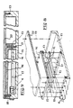
- FIGS. 8 and 9 show a practical embodiment in tri-plate technology.
- a box 15 is conventionally provided both for this comb filter and for the remaining part of the circuit (such as for example a Group Propagation Time Corrector).
- the comb filter itself is closed by a screwed cover 16 (screws 17 and 18), while a cover 20 closes, thanks to the screws 18 and 19, the housing itself 15.
- the filter which has just been described allows: - the choice of the location of a specific band; - easy modification of bandwidth during the life of the product; - to achieve the best compromise, for very wide bandwidths, between the sensitivity of the couplings, linked to the positioning accuracy of two fingers, and the physical production of the line at low impedance (for a maximum capacity value).
- MMIC application is especially interesting for the realization of integrated filters (from 500 MHz to 3 GHz in bandwidth), for future integrations between 3 and 20 GHz.
Landscapes
- Physics & Mathematics (AREA)
- Electromagnetism (AREA)
- Control Of Motors That Do Not Use Commutators (AREA)
- Filters And Equalizers (AREA)
Applications Claiming Priority (2)
| Application Number | Priority Date | Filing Date | Title |
|---|---|---|---|
| FR8913785 | 1989-10-20 | ||
| FR8913785A FR2653597B1 (fr) | 1989-10-20 | 1989-10-20 | Filtre de bande pour hyperfrequences du type filtre en peigne. |
Publications (1)
| Publication Number | Publication Date |
|---|---|
| EP0423667A1 true EP0423667A1 (de) | 1991-04-24 |
Family
ID=9386626
Family Applications (1)
| Application Number | Title | Priority Date | Filing Date |
|---|---|---|---|
| EP90119681A Withdrawn EP0423667A1 (de) | 1989-10-20 | 1990-10-15 | Mikrowellen-Bandfilter in Kammleitungsform |
Country Status (3)
| Country | Link |
|---|---|
| EP (1) | EP0423667A1 (de) |
| JP (1) | JPH03145301A (de) |
| FR (1) | FR2653597B1 (de) |
Cited By (2)
| Publication number | Priority date | Publication date | Assignee | Title |
|---|---|---|---|---|
| US6597265B2 (en) * | 2000-11-14 | 2003-07-22 | Paratek Microwave, Inc. | Hybrid resonator microstrip line filters |
| US6686817B2 (en) * | 2000-12-12 | 2004-02-03 | Paratek Microwave, Inc. | Electronic tunable filters with dielectric varactors |
Families Citing this family (2)
| Publication number | Priority date | Publication date | Assignee | Title |
|---|---|---|---|---|
| FR2777156B1 (fr) | 1998-04-09 | 2000-06-30 | Fabrice Ponsin | Nouvel ensemble support/litiere pour animal domestique, jetable par fraction |
| CN102386466A (zh) * | 2011-08-24 | 2012-03-21 | 成都赛纳赛德科技有限公司 | 可调梳形滤波器 |
Citations (4)
| Publication number | Priority date | Publication date | Assignee | Title |
|---|---|---|---|---|
| GB627870A (en) * | 1945-11-08 | 1949-08-17 | Hazeltine Corp | Wave-signal filter system |
| DE1297719B (de) * | 1967-01-12 | 1969-06-19 | Stassfurt Fernsehgeraete | Abstimmbare Leitungskreise fuer hochfrequente elektrische Schwingungen in Streifenleitertechnik |
| GB1299327A (en) * | 1971-05-26 | 1972-12-13 | Microwave Dev Lab Inc | Semi-lumped comb line filter |
| US4721931A (en) * | 1986-05-02 | 1988-01-26 | Murata Manufacturing Co., Ltd. | Stripline filter |
-
1989
- 1989-10-20 FR FR8913785A patent/FR2653597B1/fr not_active Expired - Lifetime
-
1990
- 1990-10-15 EP EP90119681A patent/EP0423667A1/de not_active Withdrawn
- 1990-10-18 JP JP28053890A patent/JPH03145301A/ja active Pending
Patent Citations (4)
| Publication number | Priority date | Publication date | Assignee | Title |
|---|---|---|---|---|
| GB627870A (en) * | 1945-11-08 | 1949-08-17 | Hazeltine Corp | Wave-signal filter system |
| DE1297719B (de) * | 1967-01-12 | 1969-06-19 | Stassfurt Fernsehgeraete | Abstimmbare Leitungskreise fuer hochfrequente elektrische Schwingungen in Streifenleitertechnik |
| GB1299327A (en) * | 1971-05-26 | 1972-12-13 | Microwave Dev Lab Inc | Semi-lumped comb line filter |
| US4721931A (en) * | 1986-05-02 | 1988-01-26 | Murata Manufacturing Co., Ltd. | Stripline filter |
Non-Patent Citations (2)
| Title |
|---|
| MICROWAVE JOURNAL. vol. 22, no. 12, décembre 1979, DEDHAM US pages 60 - 61; J.A.G.MALHERBE: "AN ETCHED DIGITAL ELLIPTIC FILTER" * |
| QST AMATEUR RADIO. vol. 52, no. 12, décembre 1968, NEWINGTON US pages 44 - 45; R.E.FISHER: "Combline V.H.F. bandpass filters" * |
Cited By (2)
| Publication number | Priority date | Publication date | Assignee | Title |
|---|---|---|---|---|
| US6597265B2 (en) * | 2000-11-14 | 2003-07-22 | Paratek Microwave, Inc. | Hybrid resonator microstrip line filters |
| US6686817B2 (en) * | 2000-12-12 | 2004-02-03 | Paratek Microwave, Inc. | Electronic tunable filters with dielectric varactors |
Also Published As
| Publication number | Publication date |
|---|---|
| FR2653597B1 (fr) | 1992-01-24 |
| FR2653597A1 (fr) | 1991-04-26 |
| JPH03145301A (ja) | 1991-06-20 |
Similar Documents
| Publication | Publication Date | Title |
|---|---|---|
| EP0047203B1 (de) | Über eine grosse Bandbreite abstimmbares Mikrowellenfilter mit einem dielektrischen Resonator | |
| FR2578104A1 (fr) | Filtre passe-bande pour hyperfrequences | |
| FR2467488A1 (fr) | Dispositif combinateur/diviseur micro-ondes a trois voies, adapte pour des resistances d'isolement externes | |
| EP0343585A1 (de) | Mikrowellen-Multiplexfilter | |
| EP0423667A1 (de) | Mikrowellen-Bandfilter in Kammleitungsform | |
| EP0281773A1 (de) | Abstimmbares Mikrowellenfilter | |
| EP0069651B1 (de) | Resonatorenfilter mit einem einstellbaren Dämpfungspol | |
| FR2509535A1 (fr) | Filtre hyperfrequence comportant des troncons de lignes couples et des moyens de reglage | |
| FR2509928A1 (fr) | Reseau de transformation d'impedance pour filtre d'ondes acoustiques de surface | |
| EP0101369A1 (de) | Banddurchlassfilter mit dielektrischen Resonatoren, mit negativer Kupplung zwischen Resonatoren | |
| EP0296929B1 (de) | Symmetrische Mikrowellenübertragungsleitung mit zwei koplanären Leitern | |
| EP0487396A1 (de) | Passives Bandpassfilter | |
| EP0738022A1 (de) | Bandpasshohlraumfilter mit Kammleitungsstruktur und Radiohöhenmesser mit einem derartigen Eingangsfilter | |
| EP0625823A1 (de) | Hyperfrequenz-Halbleiteranordnung mit Stabilisierungsmitteln | |
| EP0326498B1 (de) | Resonanzschaltung und Filter mit dergleichen | |
| EP0064458A1 (de) | Bandpassfilter, ausgeführt in Rechteckhohlleitertechnik, mit hoher Selektivität | |
| EP0346806B1 (de) | Bandpassfilter mit dielektrischen Resonatoren | |
| EP0045242A1 (de) | In Hohlleitertechnik ausgeführtes Bandpassfilter für Mikrowellen | |
| EP0983616B1 (de) | Verfahren und vorrichtung zum verbinden zweier millimeterelemente | |
| EP0430136A1 (de) | Bandsperrfilter für Mikrowellenhohlleiter | |
| EP0373028A1 (de) | Passives Bandpassfilter | |
| EP0066326A1 (de) | Gleichspannungsversorgungsvorrichtung aktiver Hochfrequenzelemente | |
| EP0337825B1 (de) | Mikrowellensperrfilter in Mikrostreifenausführung | |
| EP0018261A1 (de) | Breitbandwellenleiter mit zwei Polarisationsrichtungen | |
| EP1568098B1 (de) | Breitband-mikrowellenbandtrenneinrichtung |
Legal Events
| Date | Code | Title | Description |
|---|---|---|---|
| PUAI | Public reference made under article 153(3) epc to a published international application that has entered the european phase |
Free format text: ORIGINAL CODE: 0009012 |
|
| AK | Designated contracting states |
Kind code of ref document: A1 Designated state(s): CH DE ES FR GB IT LI NL SE |
|
| 17P | Request for examination filed |
Effective date: 19911014 |
|
| RAP1 | Party data changed (applicant data changed or rights of an application transferred) |
Owner name: ALCATEL N.V. Owner name: ALCATEL TELSPACE |
|
| 17Q | First examination report despatched |
Effective date: 19931005 |
|
| STAA | Information on the status of an ep patent application or granted ep patent |
Free format text: STATUS: THE APPLICATION IS DEEMED TO BE WITHDRAWN |
|
| 18D | Application deemed to be withdrawn |
Effective date: 19940216 |