EP0423760A2 - Lecteur de bande à inversion automatique - Google Patents
Lecteur de bande à inversion automatique Download PDFInfo
- Publication number
- EP0423760A2 EP0423760A2 EP90119917A EP90119917A EP0423760A2 EP 0423760 A2 EP0423760 A2 EP 0423760A2 EP 90119917 A EP90119917 A EP 90119917A EP 90119917 A EP90119917 A EP 90119917A EP 0423760 A2 EP0423760 A2 EP 0423760A2
- Authority
- EP
- European Patent Office
- Prior art keywords
- mode
- play
- gear
- lever
- motor
- Prior art date
- Legal status (The legal status is an assumption and is not a legal conclusion. Google has not performed a legal analysis and makes no representation as to the accuracy of the status listed.)
- Granted
Links
Images










Classifications
-
- G—PHYSICS
- G11—INFORMATION STORAGE
- G11B—INFORMATION STORAGE BASED ON RELATIVE MOVEMENT BETWEEN RECORD CARRIER AND TRANSDUCER
- G11B15/00—Driving, starting or stopping record carriers of filamentary or web form; Driving both such record carriers and heads; Guiding such record carriers or containers therefor; Control thereof; Control of operating function
- G11B15/18—Driving; Starting; Stopping; Arrangements for control or regulation thereof
- G11B15/44—Speed-changing arrangements; Reversing arrangements; Drive transfer means therefor
- G11B15/442—Control thereof
-
- G—PHYSICS
- G11—INFORMATION STORAGE
- G11B—INFORMATION STORAGE BASED ON RELATIVE MOVEMENT BETWEEN RECORD CARRIER AND TRANSDUCER
- G11B15/00—Driving, starting or stopping record carriers of filamentary or web form; Driving both such record carriers and heads; Guiding such record carriers or containers therefor; Control thereof; Control of operating function
- G11B15/18—Driving; Starting; Stopping; Arrangements for control or regulation thereof
- G11B15/26—Driving record carriers by members acting directly or indirectly thereon
- G11B15/28—Driving record carriers by members acting directly or indirectly thereon through rollers driving by frictional contact with the record carrier, e.g. capstan; Multiple arrangements of capstans or drums coupled to means for controlling the speed of the drive; Multiple capstan systems alternately engageable with record carrier to provide reversal
- G11B15/29—Driving record carriers by members acting directly or indirectly thereon through rollers driving by frictional contact with the record carrier, e.g. capstan; Multiple arrangements of capstans or drums coupled to means for controlling the speed of the drive; Multiple capstan systems alternately engageable with record carrier to provide reversal through pinch-rollers or tape rolls
Definitions
- the present invention relates to auto reverse type tape players and more particularly to an auto reverse type tape player capable of performing endless play using a battery as a power supply.
- An auto reverse type tape player is capable of selectively switching between a one-cycle mode where a tape driving motor is stopped after one cycle of forward play and reverse play, and an endless mode where the above-mentioned cycle is repeated without stopping the motor.
- a conventional auto reverse type tape player has a switch for setting the endless mode and when the user desires to repeat forward play and reverse play, he operates the above-mentioned switch to set the endless mode.
- This auto reverse type tape player includes: cam means rotating from a start position to an operation mode setting position via a mode selection position using a motor as a drive source; lever means engaged with the cam means and moving according to the rotation of the cam means, thereby switching among operation modes of a tape; drive means for moving the lever means to change a positional relation between the cam means and the lever means; selection position detecting means for detecting the cam means in the mode selection position by determining that elapsed time after start of movement of the cam means attains a preset reference time; and control means responsive to a detection signal from the selection position detecting means for controlling movement of the drive means based on an inputted operation mode signal.
- the time required for the cam means to rotate from the start position to the mode selection position by the motor under the reference voltage is calculated and this time is set as the reference time.
- problems as described below are involved.
- the voltage supplied to the motor changes according to change in the battery capacity. Consequently, the rotation speed of the motor also changes.
- the conventional tape player detects that the cam means is in the mode selection position, by determining that the elapsed time after start of movement of the cam means attains the preset reference time.
- the rotation speed of the motor changes, the time required for the cam means to attain the mode selection position also changes.
- the conventional tape player does not have a good precision for detection of the mode selection position and involves irregularity in timing for changing the positional relation between the cam means and the lever means.
- an auto reverse type tape player having first and second oscillation mechanisms is also known.
- the first oscillation mechanism includes a play gear engaging with motor drive gear means
- the second oscillation mechanism includes a fast forwarding gear engaging with the motor drive gear means.
- the first oscillation mechanism is provided to be movable among a forward play position enabling the play gear to engage with take-up reel gear means, a reverse play position enabling the play gear to engage with feed reel gear means, and an intermediate position not causing engagement of the play gear with the take-up reel gear means or the feed reel gear means.
- the second oscillation mechanism is provided to be movable among a fast forwarding position enabling the fast forwarding gear to engage with the take-up reel gear means, a rewinding position enabling the fast forwarding gear to engage with the feed reel gear means, and an intermediate position not causing engagement of the fast forwarding gear with the take-up reel gear means or the feed reel gear means.
- Each of the above-described first and second oscillation mechanisms operates by rotation force of the motor drive gear means and thus at the time of switching from the stop mode to the play mode for example, not only the first oscillation mechanism but also the second oscillation mechanism operates.
- the first oscillation mechanism reaches the forward play position or the reverse play position to set the components in the play mode before the second oscillation mechanism reaches the fast forwarding position.
- the second oscillation mechanism reaches the fast forwarding position before the first oscillation mechanism reaches the forward play position due to deviation in timing, the fast forwarding mode is temporarily set and particularly in the following situation, a considerable problem occurs.
- the take-up reel support is locked to apply an excessive load to the motor. In this case, switching of modes cannot be performed smoothly and it is feared that switching of modes cannot be made.
- An object of the present invention is to provide an auto reverse type tape player capable of easily setting an endless mode without requiring a special switch for endless mode setting.
- Another object of the present invention is to provide an auto reverse type tape player capable of accurately detecting a mode selection position and performing play mode switching operation reliably and stably.
- Still another object of the present invention is to provide an auto reverse type tape player which can prevent change to fast forwarding during mode switching operation and can perform switching of modes smoothly.
- An auto reverse type tape player is capable of selectively switching between a one-cycle mode where upon completion of one cycle of forward play and reverse play, a tape driving motor is stopped, and an endless mode where the above-mentioned cycle is repeated without stopping the motor.
- This auto reverse type tape player includes: a play button for starting forward play or reverse play; means for determining whether the play button is reoperated within a prescribed period after the play button is operated first; and means for setting the endless mode or canceling the setting in response to the detection of reoperation of play button by the determining means.
- a conventional auto reverse type tape player is provided with a special switch for endless mode setting.
- the endless mode can be set by operating the play button and thus operability is improved.
- the structure of the operation portion can be simplified.
- the present invention can be advantageously applied to an auto reverse type tape player such as a headphone stereo cassette tape player which needs to have a smaller size, a lighter weight and a smaller thickness.
- An auto reverse type tape player includes a motor, cam means, lever means, drive means, reference time storing means, reference time correcting means, selection position detecting means, and control means.
- the cam means rotates from a start position to an operation mode setting position via a mode selection position using the motor as a drive source.
- the lever means engages with the cam member and moves according to rotation of the cam means to switch operation modes of a tape.
- the drive means moves the lever means to change a positional relation between the cam means and the lever means when the cam means is in the mode selection position.
- the reference time storing means stores in advance a reference time required for the cam means to reach the mode selection position from the start position.
- the reference time correcting means corrects the reference time according to a change in rotation speed of the motor.
- the selection position detecting means detects the cam means in the mode selection position by determining that elapsed time after start of movement of the cam means attains the corrected reference time.
- the control means responds to a detection signal from the selection position detecting means and controls movement of the drive means based on an inputted operation mode signal.
- the reference time is corrected successively according to the change in the rotation speed of the motor and thus the mode selection position can be always detected accurately and the positional relation between the cam means and the lever means can be changed with good timing.
- mode selecting operation can be performed reliably and stably.
- An auto reverse type tape player includes: a drive mechanism including a reversible motor rotating in forward and reverse directions, take-up reel gear means for rotating a take-up reel support, feed reel gear means for rotating a feed reel support, motor drive gear means provided to rotate by a driving force of the motor, a first oscillation mechanism, a second oscillation mechanism, a mode switching mechanism, and an engaging mechanism.
- the first oscillation mechanism includes a play gear engaging with the motor drive gear means.
- the first oscillation mechanism is movable among a forward play position enabling the play gear to engage with the take-up reel gear means, a reverse play position enabling the play gear to engage with the feed reel gear means, and an intermediate position not causing engagement of the play gear with the take-up reel gear means or the feed reel gear means.
- the second oscillation mechanism includes a fast forwarding gear engaging with the motor drive gear means.
- the second oscillation mechanism is movable among a fast forwarding position enabling the fast forwarding gear to engage with the take-up reel gear means, a rewinding position enabling the fast forwarding gear to engage with the feed reel gear means, and an intermediate position not causing engagement of the fast forwarding gear with the take-up reel gear means or the feed reel gear means.
- the mode switching mechanism is movable by a driving force of the drive mechanism among a first position corresponding to a stop mode, a second position corresponding to a play mode, a third position corresponding to a fast forwarding mode, and a fourth position corresponding to a rewinding mode.
- the mode switching mechanism When the mode switching mechanism is in the second position, the play gear is brought to the forward play position or the reverse play position by forward rotation of the motor.
- the mode switching mechanism When the mode switching mechanism is in the third position, the mode switching mechanism brings the fast forwarding gear to the fast forwarding position by the forward rotation of the motor.
- the mode switching mechanism is in the fourth direction, it brings the fast forwarding gear to the rewinding position.
- the engaging mechanism is movable by the driving force of the drive mechanism.
- the engaging mechanism engages with the second oscillation mechanism at the time of switching between the stop mode and the play mode, so as to temporarily stop operation of the second oscillation mechanism.
- the second oscillation mechanism Since movement of the second oscillation mechanism to the fast forwarding position is stopped at the time of switching between the stop mode and the play mode, the second oscillation mechanism is reliably prevented from being in the fast forwarding state independent of the state of the tape. Accordingly, the tape player is not brought into a state making it impossible to switch modes, and thus it is possible to avoid overload to the motor and any problems caused thereby.
- a headphone stereo cassette tape player according to an embodiment of the present invention will be hereinafter described in detail with reference to the drawings.
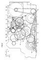
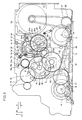
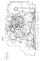
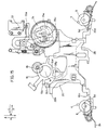
- Figs. 1 to 7 are plan views representing respective modes of a tape running mechanism of the headphone stereo cassette tape player in the embodiment of the present invention
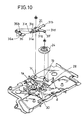
- Figs. 8 to 11 are perspective views showing assembling of the above-mentioned tape running mechanism.
- a main chassis 1 includes a take-up reel support and a feed reel support on the tape cassette loading side (i.e., the front surface of the chassis 1) and those reel supports have respective reel shafts projecting on the rear surface of the chassis 1, with their ends having a take-up gear 2 and a feed gear 3, respectively.
- a forward side (hereinafter referred to simply as FWD) capstan shaft 4 and a reverse side (hereinafter referred to simply as REV) capstan shaft 5 project on the front surface of the main chassis 1, and an FWD flywheel 6 and an REV flywheel 7 are attached to the ends of the capstan shafts 4 and 5 projecting on the rear surface.
- the flywheels 6 and 7 have pulleys 6a and 7a, and the FWD flywheel 6 further has a gear 6b.
- An FWD pinch roller 8 and an REV pinch roller 9 are disposed on the front surface of the main chassis 1, and further a sub chassis 11 having a magnetic head 10 is disposed on the front surface.
- the two pinch rollers 8, 9 are supported rotatably at ends of pinch levers 8a, 9a on one side, and the other ends of the pinch levers 8a, 9a are supported rotatably on shafts 8b, 9b, so that the pinch rollers 8, 9 are constantly maintained at positions separated from the capstan shafts 4, 5 by means of springs 8c, 9c, respectively.
- the sub chassis 11 has one end supported rotatably on the shaft 8b and it maintains the magnetic head 10 constantly at a position separated from a tape surface by means of a spring (not shown).
- the main chassis 1 supports rotatably an FWD idler gear 12, an REV idler gear 13, and an REV idler coupling gear 14.
- the FWD idler gear 12 engages with the take-up gear 2
- the REV idler gear 13 engages with the feed gear 3 and the REV idler coupling gear 14.
- a play gear shown in Fig. 12 lever 15 is supported rotatably around a shaft 1a on the main chassis 1, and a play gear 16 is supported rotatably on a shaft 15a at a suitable position of the play gear lever 15.
- the play gear lever 15 has a position where the play gear 16 is selectively engaged with the FWD idler gear 12 and the REV idler coupling gear 14 by rotation around the shaft 1a, and a neutral position where the play gear 16 is not engaged with either of the gears.
- the play gear lever 15 and the play gear 16 etc. constitute a first oscillating mechanism.
- a fast forwarding gear lever 17 is supported rotatably around the shaft 1a on the main chassis 1 and it supports rotatably fast forwarding gears 18a, 18b of the same diameter on both sides of its free end by means of a shaft 18.
- the fast forwarding gear lever 17 has a fast forwarding (FF) position enabling the gear 18a to engage with the FWD idler gear 12, and a rewinding (REW) position enabling the gear 18a to engage with the REV idler gear 13, and a neutral position not causing the gear 18a to engage with either gear.
- the fast forwarding gear lever 17 together with the fast forwarding gears 18a, 18b etc. constitutes a second oscillating mechanism.
- a slip gear 19 (as shown in Figs. 1 and 11) is a two-stage gear supported rotatably around the shaft 1a on the main chassis 1.
- a gear 19a of a larger diameter engages with the other fast forwarding gear 18b, and a gear 19b of a smaller diameter engages with the play gear 16.
- the REV idler gear 13 and the REV idler coupling gear 14 are supported by using a gear presser plate 20 (as shown in Fig. 8).
- the gear presser plate 20 is attached to the main chassis 1, although it is not shown for the purpose of simplification in figures except for Figs. 8 to 11.
- a drive transmission gear 21 and a drive conversion gear 22 are supported rotatably on the main chassis 1.
- the drive transmission gear 21 engages with the gear 6b and a gear 22a of a larger diameter of the drive conversion gear 22.
- the drive conversion gear 22 is a two-stage gear and the other gear 22b of a smaller diameter engages with a large-diameter gear 19a of a slip gear 19.
- a cam drive gear 23 is a two-stage gear supported rotatably on the main chassis 1, and it has a large-diameter gear 23a engaging with the large-diameter gear 19a of the slip gear 19, and a small-diameter gear 23b engaging with a gear of a PAD cam 24 to be described afterwards.
- the PAD cam 24 (shown in Figs. 1, 10 and 12) is supported rotatably around the shaft 1b on the main chassis 1.
- the PAD cam 24 has a gear 24a on its outer circumference, and a cam member 24b and lock portions 24c, 24d are formed on one surface of the cam 24, while a groove cam member 24e is formed on the other surface thereof.
- the gear 24a of the PAD cam 24 has non-toothed portions 24f, 24g at suitable positions.
- a motor 25 is attached to the main chassis 1. It is a brushless or coreless motor rotatable in forward and reverse directions.
- a belt 27 is placed between a motor pulley 25a and an intermediate pulley 26, as well as between the motor pulley 25a and pulleys 6a, 7a of the flywheels 6, 7.
- a sub operation lever 28 (as shown in Fig. 9) is provided movably in the directions of the arrows A, B within the ranges of elongate holes 28a, 28b in which shafts 1c, 1d provided on the gear presser plate 20 and the main chassis 1 are inserted, respectively, and the lever 28 is constantly actuated in the direction of the arrow B by means of a spring 29.
- the sub operation lever 28 has a pin 28c at a suitable position and this pin 28c is brought into contact with the cam member 24e of the PAD cam 24, whereby the lever 28 moves in the directions of the arrows A, B by means of the cam member 24e when the PAD cam 24 is rotated (as shown in Fig. 12).
- the sub operation lever 28 has a projecting pressing portion 28f, which contacts a contact portion 11a of the sub chassis 11. According to the movement of the sub operation lever 28 in the direction of the arrow A, the sub chassis 11 advances in opposition to the spring, causing the magnetic head 10 to contact the tape surface.
- the sub operation lever 28 has a switch operating portion 28h and when the lever 28 moves in the direction of the arrow A, a play mode detection switch (not shown) is turned on by means of the switch operating portion 28h.
- a pinch roller operation lever 30 (as shown in Figs. 9 and 12) has bending portions 30a, 30b inserted in openings 28d, 28e, respectively, whereby the lever 30 moves together with the sub operation lever 28 in the directions of the arrows A, B and is movable in the directions of the arrows C, D in the ranges of the openings 28d, 28e.
- the pinch roller operation lever 30 has pinch roller operating portions 30c, 30d.
- the play gear lever 15 has right and left projecting contact portions 15b, 15c, an almost pentagonal hole 15d, and a slit 15e continuous with the hole 15d.
- the pinch roller operation lever 30 has a bending portion 30f to be opposite to the contact portion 15b when the lever 30 moves in the direction of the arrow D, and a bending portion 30g to be opposite to the contact portion 15c when the lever 30 moves in the direction of the arrow C.
- the sub operation lever 28 has a bending portion 28g which is inserted movably in the hole 15d of the play gear lever 15.
- the bending portion 28g is fitted in the slit 15e continuous with the hole 15d, whereby the play gear lever 15 is returned to the neutral position and is maintained in the neutral position.
- the play gear lever 15 includes a projecting portion 15h having switch operating portions 15f, 15g.
- an FWD/REV detection switch (not shown) is operated by means of the switch operating portion 15f, and when the lever 15 rotates counterclockwise, the FWD/REV detection switch is operated by means of the switch operating portion 15g.
- the fast forwarding gear lever 17 has a projecting contact portion 17c to be opposite to the bending portion 30f of the pinch roller operation lever 30.
- the fast forwarding gear lever 17 is prevented from rotating counterclockwise from the neutral position, as a result of contact between the bending portion 30f and the contact portion 17c.
- the fast forwarding gear 18a is prevented from engaging with the FWD idler gear 12.
- a solenoid lever 31 (as shown in Figs. 1, 10 and 12) is supported rotatably around the shaft 1c and it has arms 31a to 31d extending in four directions.
- the solenoid lever 31 has a bent form including a portion having the arms 31a to 31c and a portion having the arm 31d with those portions being located at a prescribed angle from each other around the shaft 1c.
- a spring 31 is disposed between the arm 31a and the main chassis 1 to actuate the lever 31 constantly clockwise around the shaft 1c.
- the arm 31b is connected to an iron core 33a of the solenoid 33 mounted on the main chassis 1.
- the solenoid 33 is of a self-holding type. When the solenoid 33 is in a non-conducting state, it absorbs and holds the iron core 33a by means of an incorporated permanent magnet in opposition to the actuating force of the spring 32. When the solenoid 33 is in a conducting state, it generates a magnetic force opposite to the absorbing direction of the permanent magnet and a resultant force of the magnetic force and the actuating force of the spring 32 overcomes the absorbing force of the permanent magnet to rotate the solenoid lever 31 clockwise and thus the iron core 33a is separated from the permanent magnet. When the iron core 33a is separated from the permanent magnet at a prescribed distance, the permanent magnet does not absorb the iron core 33a if the conduction of the solenoid 33 is stopped.
- the arm 31c cooperates with a fast forwarding engaging lever 34 (as shown in Figs. 1, 2 and 3).
- the fast forwarding engaging lever 34 is supported rotatably around the shaft le on the main chassis 1, and it has an engaging portion 34a at one end and a bending portion 34b at the other end.
- the fast forwarding engaging lever 34 supports a torsion spring 35.
- the bending portion 34b, and a projecting portion 31e at the top end of the arm 31c of the solenoid lever 31 are located between both ends of the torsion spring 35, whereby the fast forwarding engaging lever 34 rotates together with the solenoid lever 31 by means of the torsion spring 35.
- the engaging portion 34a engages with and disengages from a left portion 17a of a T-shaped top end of the fast forwarding gear lever 17 by rotation of the fast forwarding engaging lever 34.
- a right portion 17b of the T-shaped top end prevents the engaging portion 34a of the fast forwarding engaging lever 34 from entering a right side portion in the figure of the fast forwarding gear lever 17.
- the arm 31d of the solenoid lever 31 has a projecting pin 31f, which is associated with the cam member 24b and lock portions 24c, 24d of the PAD cam 24.
- a selection lever 36 (as shown in Figs. 10 and 12) is supported rotatably around the shaft 1c in the same manner as in the case of the solenoid lever 31, and the selection lever 36 is actuated constantly clockwise around the shaft 1c by means of a spring 37 provided between a spring engaging portion 36a and the arm 31a of the solenoid lever 31.
- the selection lever 36 has a projecting pin 36b at a suitable position.
- the pin 36b is inserted movably in an almost parallelogram hole 31g formed in the solenoid lever 31, and the pin 36b is pressed against the left edge of the hole 31g by the actuating force of the spring 37.
- the solenoid lever 31 and the selection lever 36 can be rotated together around the shaft 1c by means of the spring 37.
- the selection lever 36 has another pin 36c on the surface opposite to the surface including the above-mentioned pin 36b.
- the pin 36c is inserted movably in a guide hole 30e formed in the pinch roller operation lever 30, causing the pinch roller operation lever 30 to move in the directions of the arrows C, D by rotation of the selection lever 36.
- the above-mentioned PAD cam 24, motor 25, solenoid lever 31, solenoid 33, selection lever 36 and so on constitute a driving mechanism for switching modes in the respective components.
- the fast forwarding engaging lever 34, torsion spring 35 and so on constitute an engaging mechanism for engaging the fast forwarding gear lever 17 to prevent the counterclockwise rotation of the lever 17, namely, the movement thereof to the FF position.
- the above-mentioned sub operation lever 28, pinch roller operation lever 30 and so on constitute a mode selection mechanism operated by the above-mentioned driving mechanism to select any mode such as a play mode, a fast forwarding mode, or a rewinding mode.
- Figs. 12 to 16 are explanatory views showing operations of the PAD cam 24 and other components.
- Fig. 17 is a schematic plan view showing an arrangement of a printed circuit board, a motor and the PAD cam etc.
- Fig. 18 is a cross sectional view taken along A-A of Fig. 17.
- a main frame 38, together with the main chassis 1, a cabinet 40 etc. constitute an outer shape of the main body of the player
- a printed circuit board 39 is formed integrally with a control circuit board portion 39a and a drive board portion 39b by one plate by means of a narrow coupling portion 39c, with necessary electric components 39d being mounted on front and rear surfaces of the control circuit board portion 39a.
- the control circuit board portion 39a and the driving board portion 39b of the printed circuit board 39 are located at different levels by making use of flection of coupling portion 39c.
- the reason for this arrangement is as follows.
- the maximum height of the electric component 39d mounted on the control circuit board portion 39a is different from the heights of the motor 25 and solenoid 33 mounted on the driving board portion 39b and, if the two board portions 39a and 39b are located at the same level, the thickness of the main body of the player would be increased.
- the board portions 39a and 39b are mounted at the different levels, whereby the main body of the player can be made thin.
- the PAD cam 24 according to the embodiment is located near the motor 25 and solenoid 33, which makes it possible to further reduce the outer shape of the main body of the player. The reason for this is described below.
- the PAD cam was located in a position show by the reference character 24 (as shown in Fig. 17) and accordingly, it would be necessary to remove the portion 39e surrounded by the chain line in the printed circuit board 39 to ensure the space for the cam.
- an insufficient space for the electric component 39d would be compensated for by an external portion of the control circuit board portion 39a (on the side opposite to the tape running mechanism), causing an increase of the main frame 39 and accordingly an increase of the size of the main body of the player.
- the PAD cam 24 is located in proximity to the motor 25 and solenoid 33, which makes it possible to solve the above-mentioned problem and to reduce the size of the main body of the player.
- the reference characters 2a denote the take-up reel support
- the reference characters 3a denote the feed reel support
- Fig. 19 is a block diagram showing a control system of the above-described tape player.
- the control system includes a control circuit 41 formed mainly by a microcomputer, a play switch 42, a fast forwarding (FF) switch 43, a rewinding (REW) switch 44, and a stop switch 45.
- the switches 42 to 45 are operated by a play button, an FF button, an REW button and a stop button, respectively.
- the control system further includes: an initial switch 46 which is turned on when an ejection button for ejecting the tape cassette is operated, when a headphone or earphone jack is detached from the main body of the player, or when a battery supply is removed from the main body of the player; a play mode detection switch 47 which detects a play mode by movement of the sub operation lever 28; an FWD/REV detection switch 48 which detects an FWD/REV condition by movement of the play gear lever 15; a motor voltage detector 49 which detects voltage supplied to the motor 25; and a rotation detector 50 which detects rotation of the FWD idler gear 12.
- the rotation detector 50 is formed for example by a photo-coupler.
- a surface of the FWD idler gear 12 has a black-and-white striped pattern as known in the prior art, and when the idler gear 12 rotates, the rotation detector 50 generates pulses periodically.
- the control system further includes a solenoid drive circuit 51, and a motor drive circuit 52.
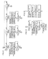
- Control and signal processing of the respective components by the control circuit 41 will be described in the following description of operation of the player with reference to flow charts of Figs. 20 to 25.
- the stop mode includes three modes, namely, the first stop mode (as shown in Fig. 3) changed from the play mode, the second stop mode (as shown in Fig. 1) changed from the FF mode, and the third stop mode (as shown in Fig. 2) changed from the REW mode.
- Fig. 12 represents an operation condition common to each of the stop modes since the fast forwarding gear lever 17 and the fast forwarding engaging lever 34 are not shown.
- the components are in the following states.
- the sub chassis 11 and the sub operation lever 28 are moved in the direction of the arrow B and the pinch roller operation lever 30 is moved in the direction of the arrow D.
- the play gear lever 15 maintains the play gear 16 in the neutral position and the fast forwarding gear lever 17 maintains the fast forwarding gear 18a in the neutral position with the left portion 17a of the lever 17 being engaged with the engaging portion 34a of the fast forwarding engaging lever 34.
- the non-toothed portion 24f of the PAD cam 24 is opposed to the small-diameter gear 23b of the cam drive gear 23 and the pin 31f of the solenoid lever 31 is engaged with the lock portion 24c of the cam 24.
- the FWD and REV pinch rollers 8, 9 are separated from the capstan shafts 4, 5.
- the control circuit 41 determines the turn-on of the play switch 42 and stores the setting of the play mode in memory. At the same time, the control circuit 41 reads a control program of the play mode from the memory and performs the following control operation.
- control circuit 41 determines the turn-on of the play switch 42 in step S1 of the flow chart of Fig. 20, the control circuit 41 supplies a signal to the motor drive circuit 52 in step S2 to drive the motor 25 counterclockwise and to start counting for time T1.
- the above-mentioned time T1 is a very short time which is predetermined based on time required for at least the engaging portion 34a to disengage from the left portion 17a from the start of drive of the motor 25.
- step S3 the processing flow proceeds to step S4, in which a signal is supplied to the motor drive circuit 52 to reverse the rotation of the motor 25, namely, to rotate the motor 25 clockwise, and a signal is supplied to the solenoid drive circuit 51 to conduct the solenoid 33 with a single pulse and to start operation thereof, and counting for time T2 is started.
- the solenoid 33 generates a magnetic force instantaneously by the conduction with the single pulse. Then, a resultant force of the magnetic force and the actuating force of the spring 32 overcomes the absorbing force of the internal permanent magnet of the solenoid 33 to rotate the solenoid lever 31 clockwise around the shaft 1c and to project the iron core 33a. Although the conduction of the solenoid 33 is effected instantaneously, the solenoid lever 31 is kept rotated clockwise by the actuating force of the spring 32.
- the state immediately after the start of operation of the solenoid 33 is shown in Figs. 4 and 13.
- the solenoid lever 31 rotates clockwise to move the pin 31f away from the lock portion 24c of the PAD cam 24 and to rotate the fast forwarding engaging lever 34 counterclockwise around the shaft le through the torsion spring 35, thereby returning it to the initial position. Since the fast forwarding engaging lever 34 is returned to the initial position, when the fast forwarding gear lever 17 rotates counterclockwise around the shaft 15a according to the clockwise rotation of the motor 25, the fast forwarding engaging lever 34 engages with the fast forwarding gear lever 17, whereby the fast forwarding gear 18a is prevented from engaging with the FWD idler gear 12 and thus the FF condition is prevented from being set.
- the selection lever 36 rotates clockwise around the shaft 1c together with the solenoid lever 31 through the spring 37, whereby the pin 36c pushes a wall surface of the guide hole 30e of the pinch roller operation lever 30 to move the pinch roller operation lever 30 in the direction of the arrow C.
- the clockwise rotation force of the motor 25 is transmitted to the cam drive gear 23 through the belt 27, the gear 6b of the FWD flywheel 6, the drive transmission gear 21, the drive conversion gear 22, and the slip gear 19, and the clockwise rotation of the cam drive gear 23 causes the PAD cam 24 engaged with the small-diameter gear 23b to rotate counterclockwise.
- the control circuit 41 detects, in step S4, a voltage V1 supplied from the motor voltage detector 49 to the motor 25 immediately after the conduction of the solenoid 33 with the single pulse, reads out a reference voltage V2 stored in the memory, and subtracts the supplied voltage V1 from the reference voltage V2 to obtain a value ⁇ V. Then, the control circuit 41 multiplies the value AV by a constant h to obtain a time deficiency t1 and the time deficiency t1 is added to the reference time t so that the value obtained by the addition is used as the above-mentioned time T2.
- the reference voltage V2 is preset higher than the voltage supplied to the motor 25, and the reference time V2 is set to time required for the PAD cam 24 to reach the position in Fig. 14 from the position in Fig. 13 when the above-mentioned reference voltage V2 is supplied to the motor 25.
- the rotation speed and the supplied voltage of the motor 25 are in a proportional relation. If the supplied voltage V1 is lower than the reference voltage V2, the PAD cam 24 could not reach the position shown in Figs. 5 and 14 from the position shown in Figs. 4 and 13 in the above-mentioned reference time t and consequently a value necessary for obtaining the time deficiency t1 based on the above-mentioned difference ⁇ V of voltages is calculated in advance as the constant h.
- control circuit 41 makes correction for the time T2 in step S5 and when it is determined in step S6 that the time T2 has passed, the control circuit 41 reads the FWD play or the REV play as the previous play mode stored in the memory in step S7.
- step S8 a signal is supplied to the solenoid drive circuit 51 in step S8, so that the solenoid 33 is conducted with a single pulse.
- the cassette tape player includes: the PAD cam 24 rotated by the motor 25 as the drive source; the solenoid lever (lever member) 31 which is operated by the cam 24 to switch modes and is capable of changing the positional relation with the PAD cam 24 in a mode selection position in the rotation course of the PAD cam 24; the solenoid (drive means) 33 which moves the solenoid lever 31 to change the positional relation between the PAD cam 24 and the solenoid lever 31; and the motor voltage detector 49 which detects a change in the rotation speed of the motor 24 by a change in the supplied voltage.
- control circuit 41 includes: selection position detecting means for making correction for the preset time based on the detected by the motor voltage detector 49 and providing a mode selection position detecting signal when the elapsed time after the start of operation of the PAD cam 24 attains the time obtained by the correction; and control means for operating the solenoid 33 when the mode selection detecting signal is inputted from the selection position detecting means and a signal (FWD play signal) based on a play mode switching instruction is inputted.
- the solenoid lever 31 rotates clockwise in the same manner as described above to cause the pin 31f to contact and slide over a cam surface 24b3 of the cam member 24 which continues rotating counterclockwise.
- the selection lever 36 is also rotated clockwise and the pin 36c pushes a wall surface of the guide hole 36e of the pinch roller operation lever 30, causing the operation lever 30 to move in the direction of the arrow C.
- the fast forwarding engaging lever 34 also receives the counterclockwise rotation force around the shaft 1e and is kept engaged with the fast forwarding lever 17.
- the PAD cam 24 starts to rotate the solenoid lever 31 counterclockwise through the pin 31f pressed against a cam surface 24b4 of the cam member 24b.
- the selection lever 36 rotates counterclockwise according to the movement of the solenoid lever 31, without moving the pinch roller operation lever 30 in the direction of the arrow D.
- the pinch roller operation lever 30 is in the state moved in the direction of the arrow C.
- the permanent magnet contained in the solenoid 33 absorbs the iron core 33a.
- the clockwise rotation force is applied to the fast forwarding engaging lever 34, the fast forwarding engaging lever 34 does not rotate clockwise since it is engaged with the fast forwarding lever 17, and the above-mentioned rotation force is absorbed by the torsion spring 35.
- the sub operation lever 28 and the pinch roller operation lever 30 continue to move in the direction of the arrow A and the sub operation lever 28 presses the contact portion 11a (as shown in Fig. 1) by means of its pressing portion 28f to rotate the sub chassis 11 counterclockwise around the shaft 8b, whereby the magnetic head 10 advances in the direction of the arrow A and contacts the tape surface, not shown.
- the pinch roller operation lever 30 presses the contact portion c by means of the bending portion 30g to rotate the play gear lever 15 counterclockwise around the shaft 1a and to engage the play gear 16 with the FWD idler gear 12.
- the pinch roller operation lever 30 presses the spring 8d by means of the pinch roller operating portion 30c to rotate the pinch lever 8a counterclockwise around the shaft 8b, so that the FWD pinch roller 8 is pressed against the FWD capstan shaft 4 with the magnetic tape being put therebetween.
- the play mode detection switch 47 is turned on and the FWD/REV detection switch 48 is turned to the FWD play side by means of the switch operating portion 15f of the play gear lever 15.
- the control circuit 41 stores the FWD play.
- the tape running mechanism is set in the FWD play mode and is in the condition as shown in Figs. 6 and 16.
- the play gear 16 engages with the FWD idler gear 12
- the lock portion 24d Of the PAD cam 24 engages with the pin 31 of the solenoid lever 31 and the counterclockwise rotation of the PAD cam 24 is stopped with the non-toothed portion 24g being opposed to the small-diameter gear 23b of the cam drive gear 23.
- the control circuit 41 operates the reproduction circuit in step S9 so that music information recorded in the magnetic tape is read and reproduced by the magnetic head 10.
- the user can enjoy listening to the reproduced sound by means of earphones or headphones.
- the FWD play namely, the FWD reproduction is performed.
- the control circuit 41 performs the same control operation as in the above-described steps S1 to S7 and the tape running mechanism is also operated in the same manner.
- step S7 When it is determined in step S7 that the previous play mode is the REV mode, the mode switches to the REV mode.
- the switching to the REV mode is effected by continuing the counterclockwise rotation of the PAD cam 24 without conducting the solenoid 33 in the position shown in Figs. 5 and 14, as in the FWD mode.
- the cam member 24e of the PAD cam 24 pushes the pin 28c of the sub operation lever 28 to move the sub operation lever 28 in the direction of the arrow A together with the pinch roller operation lever 30, whereby the bending portion 28g and the pin 36c of the selection lever 36 are moved away from the slit 35e and the guide hole 30e, respectively.
- the pressing portion 28f rotates the sub chassis 11 counterclockwise around the shaft 8b by means of the contact portion 11a (as shown in Fig. 1), causing the magnetic head 10 to be in contact with the tape surface.
- the pinch roller operating portion 30d rotates the pinch lever 9a around the shaft 9b by means of the operation spring 9d, whereby the REV pinch lever 9 is pressed against the REV capstan shaft 5 with the tape being put therebetween. Further, the bending portion 30f contacts the contact portion 15b of the play gear lever 15 to rotate the play gear lever 15 clockwise around the shaft 1a, whereby the play gear 16 engages with the REV idler coupling gear 14 (as shown in Fig. 1).
- the PAD cam stops with the pin 31f being engaged with the lock portion 24d, and the non-toothed portion 24g being opposite to the small-diameter gear 23b of the cam drive gear 23.
- the REV play mode shown in Figs. 7 and 15 is set.
- the play mode detection switch 47 is on as in the case of the FWD mode, and the FWD/REV detection switch 48 is set to the REV play side by means of the switch operating portion 15f of the play gear lever 15.
- the control circuit 41 stores the REV play in the memory.
- the tape running mechanism is switched to the REV play mode and is in the state as shown in Figs. 7 and 15.
- the play gear 16 engages with the REV idler coupling gear 14
- the counterclockwise rotation of the PAD cam 24 is stopped by the engagement of the pin 31f of the solenoid lever 31 with the lock portion 24d and the non toothed portion 24g is opposed to the small-diameter gear 23b of the cam drive gear 23.
- the control circuit 41 operates the reproduction circuit in step S9 so that the music information recorded in the magnetic tape is read and reproduced by means of the magnetic head 10.
- the user can enjoy listening to the reproduced sound by means of earphones or headphones.
- the REV play namely, the REV reproduction is performed.
- the control circuit 41 determines the turn-on of the stop switch 45 and reads a corresponding control program from the memory, and it performs control operation as shown in the flow chart of Fig. 22.
- control circuit 41 determines the turn-on of the stop switch 45 in step S10 in Fig. 21, it determines by means of the play mode detection switch 47 in step S11 of Fig. 22 whether the mode presently selected is the play mode or not.
- the solenoid 33 is conducted with a single pulse and counting for time T3 is started.
- the solenoid 33 generates instantaneously a magnetic force as a result of the conduction with the single pulse. Consequently, as described previously, the solenoid lever 31 rotates clockwise around the shaft 1c to disengage the pin 31f from the lock portion 24d of the PAD cam 24 and to rotate the fast forwarding engaging lever 34 counterclockwise around the shaft le by means of the torsion spring 35. By the counterclockwise rotation of the fast forwarding engaging lever 34, the fast forwarding engaging lever 34 returns to the initial position enabling engagement with the fast forwarding gear lever 17.
- the selection lever 36 also rotates clockwise together with the solenoid lever 31, causing the pin 36c to be opposite to the guide hole 30e of the pinch roller operation lever 30.
- the pin 31f comes out of the lock portion 24d and presses against a cam surface 24b5 of the cam member 24b to rotate the PAD cam 24 counterclockwise and to engage the gear 24a with the small-diameter gear 23b of the cam drive gear 23.
- the PAD cam 24 rotates by the clockwise rotation force of the cam drive gear 23 and the pin 31f slides on a cam surface 24b6 of the cam member 24b.
- the cam member 24e pushes the pin 28c to move the sub operation lever 28 in the direction of the arrow B.
- the sub chassis 11 rotates clockwise around the shaft 8b to separate the magnetic head 10 from the magnetic tape.
- the bending portion 28g contacts an oblique edge of the hole 15d of the play gear lever 15 to rotate the lever 15 clockwise around the shaft 1a, causing the play gear 16 to return to the neutral position.
- the stopped state of the fast forwarding gear lever 17 by means of the bending portion 30f is canceled but since the left portion 17a engages with the engaging portion 34a of the fast forwarding engaging lever 34, the fast forwarding gear 18a is maintained in the neutral position.
- the pinch roller operating portion 30c is separated from the spring 8d and the FWD pinch roller 8 is separated from the FWD capstan 4 by the actuating force of the spring 8c, with the guide hole 30e being opposite to the pin 36c.
- the control circuit 41 stores the FWD mode as the present play mode.
- the above-mentioned time T3 will be described hereinafter.
- the time T3 is set based on the time until the tape running mechanism switches to the state shown in Figs. 3 and 12 after the conduction of the solenoid 33 in step S12, and this time T3 is used as a value for controlling the timing for turning off the motor 25. Consequently, correction processing is performed with respect to the time T3 based on the voltage applied to the motor 25 in the same manner as described previously in connection with the time T2, whereby the motor 25 can be turned off reliably in the state shown in Figs. 3 and 12. Such correction processing is performed in step S13.
- the control circuit 41 determines in step S14 that the time T3 has passed, it supplies a signal to the motor drive circuit in step S15 to stop the motor 25.
- the mode switches from the FWD play mode to the first stop mode.
- the control circuit 41 determines the turn-on of the switch 45 and controls the respective components according to a prescribed control program. Since the control operation is the same as in the case of the above-described case of "FWD play mode - first stop mode", the description thereof is not repeated.
- the control circuit 41 determines the turn-on of the FF switch 43 and stores the setting of the FF mode in the memory. At the same time, the control circuit 41 reads a control program of the FF mode from the memory and performs control operation as shown in the flow chart of Fig. 20.
- control circuit 41 determines the turn-on of the FF switch 43 in step S1
- the control circuit 41 supplies a signal to the motor drive circuit 52 in step S16 to rotate the motor 25 counterclockwise and to start counting for the time T1.
- step S16 is the same as that in step S2 and the operation of the tape running mechanism in this case is also the same as described previously. Accordingly, when the elapse of the time T1 is determined in step S17, the fast forwarding gear lever 17 rotates clockwise around the shaft 1a as shown in Fig. 3, and the fast forwarding engaging lever 34 cancels the engagement between the engaging portion 34a and the left portion 17a and is rotated clockwise around the shaft 1e by means of the torsion spring 35.
- the control circuit 41 supplies a signal to the motor drive circuit 52, so that the motor 25 rotates reversely, namely, clockwise. Then, the clockwise rotation force of the motor 25 is transmitted to the slip gear 19 through the motor pulley 25a, belt 27, pulley 6a, gear 6b, drive transmission gear 21 and drive conversion gear 22, and by the counterclockwise rotation of the slip gear 19, the fast forwarding gear lever 17 which engages the fast forwarding gear 18b with the large-diameter gear 19a rotates counterclockwise around the shaft 1a.
- the fast forwarding gear 18a on the same shaft as for the fast forwarding gear 18b is engaged with the FWD idler gear 12. After the engagement, the fast forwarding gear 18a rotates clockwise around the shaft 18 and the rotation force thereof is transmitted to the take-up gear 2 through the FWD idler gear 12.
- the control circuit 41 stores the setting of the stop mode by the turn-on of the stop switch 45 in the memory and reads a corresponding program from the memory to perform control operation.
- control circuit 41 determines in step S11 in Fig. 22 whether the present mode is the play mode or not. In this case, the sub operation lever 28 is kept away in the direction of the arrow B and the play mode detection switch 47 is off. Thus, the control circuit 41 determines that the mode is not the play mode, and supplies immediately a signal to the motor drive circuit 52 in step S15 to stop the motor 25.
- the only difference from the FF mode is that the motor 25 stops.
- the state of Fig. 1 represents the FF mode and also the second stop mode.
- the control circuit 41 determines the turn-on of the REW switch 44 and stores the setting of the REW mode in the memory. At the same time, the control circuit 41 reads out a control program of the REW mode from the memory and performs control operation as shown in the flow chart of Fig. 20.
- control circuit 41 After the determination of the turn-on of the REW switch 44 in step S1, the control circuit 41 supplies a signal to the motor drive circuit 52 in step S21 to rotate the motor counterclockwise.
- FIG. 2 This state is shown in Fig. 2, in which the feed reel support rotates counterclockwise, namely, in the tape take-up direction at high speed and the magnetic tape of the tape cassette runs at high speed in the rewinding direction.
- control circuit 41 When the stop switch 45 is turned on by depressing the stop button in the REW mode, the control circuit 41 stores the setting of the stop mode by the turn-on of the stop switch 45 in the memory and reads out a corresponding program from the memory to perform control operation.
- the control circuit 44 determines in step S11 in Fig. 22 whether the present mode is the play mode or not. In this case, the sub operation lever 28 is kept away in the direction of the arrow B and the play mode detection switch 47 is off. Thus, the control circuit 41 determines that the present mode is not the play mode and supplies immediately a signal to the motor drive circuit 52 in step S15 to stop the motor 25.
- the difference from the REW mode is that the motor 25 stops, and the state of the respective components of the tape running mechanism is the same as in Fig. 2.
- the state of Fig. 2 represents the REW mode and the third stop mode.
- the control circuit 41 stores in the memory the setting of the FF mode by the turn-on of the FF switch 43 and reads out a corresponding program from the memory to perform control operation.
- control circuit 41 determines the turn-on of the FF switch 43 in step S10 where the FWD or REV play mode is currently set, the control circuit 41 performs control at first to return the mode to the first stop mode. More specifically, as shown in Fig. 21, the same control operation as in steps S12 to S14 in Fig. 22 described above in detail in the case of "FWD play mode ⁇ first stop mode". Needless to say, the operation of the tape running mechanism at this time is the same as described above.
- control circuit 41 determines the elapse of the time T3
- the state of the respective components of the tape running mechanism is switched to the state shown in Figs. 3 and 12.
- the control circuit 41 performs the same control operation as in steps S16 to S18 in Fig. 20 described previously in the case of "first stop mode ⁇ FF mode".
- the tape running mechanism is switched to the FF mode shown in Fig. 1, and the magnetic tape of the tape cassette runs in the FF direction, at high speed.
- the mode switches from the FWD or REV play mode to the FF mode.
- control circuit 41 When the REW switch 44 is turned on by depressing the REW button in the FWD or REV play mode, the control circuit 41 stores in the memory the setting of the REW mode by the turn-on of the REW switch 44 and reads out a corresponding program from the memory to perform control operation.
- control circuit 41 After the control circuit 41 determines the turn-on of the REW switch 44 in step S10 where the FWD or REV play mode is currently set, the control circuit 41 performs control at first to return the mode to the first stop mode. More specifically, as shown in Fig. 21, the control circuit 41 performs the same control operation as in steps S12 to S14 in Fig. 22 described above in detail in the case of "FWD play mode ⁇ first stop mode". The operation of the tape running mechanism during this control is also the same.
- control circuit 41 determines the elapse of the time T3
- the state of the respective components of the tape running mechanism is changed to the state shown in Figs. 3 and 12.
- the control circuit 41 performs the same control operation as in step S21 in Fig. 20 described previously in the case of "first stop mode ⁇ REW mode".
- the tape running mechanism is switched to the REW mode shown in Fig. 2, in which the magnetic tape of the tape cassette runs at high speed in the rewinding direction.
- the mode switches from the FWD or REV play mode to the REW mode.
- the control circuit 41 stores in the memory the setting of the play mode by the turn-on of the play switch 42 and reads out a corresponding program from the memory to perform control operation.
- control circuit 41 determines the turn-on of the play switch 42 in step S20 or S23 where the FF or REW mode is currently set, it performs the same control operation as in steps S2 to S9 in Fig. 20 described above in detail in the case of "first stop mode ⁇ FWD play mode". During this control operation, the operation of the tape running mechanism is the same as described above, and then the mode switches to the play mode. Whether the play mode to be set is the FWD play mode or the REV play mode is determined by the previous play mode stored in the memory of the control circuit 41.
- step S2 When the motor 25 is rotated counterclockwise in step S2, the fast forwarding gear 18a engages with the REV idler gear 13 as shown in Fig. 2 at the time of switching from the REW mode to the play mode and consequently, the feed reel support is rotated in the rewinding direction even after the depression of the play button.
- the counterclockwise rotation of the motor 25 is limited only for the time T1 which is very short as described above and therefore there is no practical problem.
- the control circuit 41 stores in the memory the setting of the REW mode by the turn-on of the REW switch 44 and reads out a corresponding program from the memory to perform control operation.
- the rotating direction of the motor 25 is switched from the clockwise direction to the counterclockwise direction as shown in step S21. Consequently, the rotating direction of the slip gear 19 also changes from the counterclockwise direction to the clockwise direction and the fast forwarding gear lever 17 rotates clockwise around the shaft 1a from the position shown in Fig. 1.
- the fast forwarding gear 18a which has been engaged with the FWD idler gear 12 is separated from the FWD idler gear 12 and is engaged with the REV idler gear 13 and the state as shown in Fig. 2 is set.
- the rotation of the slip gear 19 is transmitted to the feed gear 3 through the fast forwarding gears 18b, 18a and REV idler gear 13, and the feed reel support rotates in the rewinding direction, whereby the REW mode is applied.
- the control circuit 41 When the FF switch 43 is turned on by depressing the FF button in the REW mode, the control circuit 41 stores in the memory the setting of the FF mode by the turn-on of FF switch 43 and reads out a corresponding program from the memory to perform control operation.
- the control circuit 41 determines the turn-on of the FF switch 43 in step S23 where the REW mode is currently set, the control circuit 41 switches the rotating direction of the motor 25 from the counterclockwise direction to the clockwise direction as shown in step S18. Then, the rotating direction of the slip gear 19 also changes from the clockwise direction to the counterclockwise direction and the fast forwarding gear lever 17 rotates counterclockwise around the shaft 1a from the position shown in Fig. 2.
- the fast forwarding gear 18a which has been engaged with the REV idler gear 13 is separated from the REV idler gear 13 and is engaged with the FWD idler gear 12 and thus the state shown in Fig. 1 is set.
- the control circuit 41 stores in the memory the setting of the play direction switching mode by the turn-on of the play switch 42 and reads out a corresponding program from the memory to perform control operation.
- control circuit 41 After the determination of the turn-on of the play switch 42 in step S10 where the FWD play mode is currently set, the control circuit 41 performs control at first to return the mode to the first stop mode. More specifically, it performs the same control operation as in steps S12 to S14 in Fig. 22 described in detail in the case of "FWD play mode ⁇ first stop mode", as shown in Fig. 21. The operation of the tape running mechanism during this control is also the same as described above.
- control circuit 41 determines the elapse of the time T3
- the state of the respective components of the tape running mechanism is changed to the state shown in Figs. 3 and 12.
- the control circuit 41 performs the same control operation as in steps S2 to S6 in Fig. 20 described in connection with the case of "first stop mode ⁇ FWD play mode".
- the tape running mechanism is switched to the FWD/REV selection position shown in Figs. 5 and 14.
- the previous play mode stored in the memory is read in step S7 so that the same play mode is set.
- the control program is executed so that the present play mode is different from the previous play mode.
- control circuit 41 determines the elapse of the time T2, it reads out the previous play mode (the FWD play mode in this case) and makes determination based on the previous play mode thus read, so that the REV play mode is set.
- the tape running mechanism operates to be switched from the FWD/REV selection position shown in Figs. 5 and 14 to the REV play mode shown in Figs. 7 and as described in detail in the case of "first stop mode ⁇ REV play mode", whereby REV play is performed.
- the mode switches from the FWD play mode to the REV play mode.
- the control circuit 41 stores in rhe memory the setting of the play direction switching mode by the turn-on of the play switch 42 and reads out a corresponding program from the memory to perform control operation.
- control circuit 41 determines the turn-on of the play switch 42 in step S10 where the REV play mode is set, the control circuit 41 performs the same control operation as described above in the case of "FWD play mode ⁇ REV play mode" and after the mode of the tape running mechanism is temporarily switched to the first stop mode shown in Figs. 3 and 12, the position of the tape running mechanism is changed to the FWD/REW selection position shown in Figs. 5 and 14.
- control circuit 41 determines the elapse of the time T2, it reads out the previous play mode (the REV play mode in this case) and makes determination based on this mode. As a result, the control circuit 41 sets the FWD play mode opposite to the REV play mode and performs control operation shown in step S8 in Fig. 20.
- the tape running mechanism operates to be switched to the FWD play mode shown in Figs. 6 and 14 from the FWD/REV selection position as described in detail in the case of "first stop mode ⁇ FWD play mode", so that FWD play is performed.
- the mode switches from the REV play mode to the FWD play mode.
- a rotation detector 50 used for the tape end detection is a well-known detector including a black-and-white striped pattern on the surface of the FWD idler gear 12 rotating in either of the FWD, REV play modes, a light emitting portion emitting light to the surface of the idler gear 12, and a light receiving portion receiving light reflected on the white stripes. While the FWD idler gear 12 is rotating, reflection of light on the white stripes and absorption of light on the black stripes are repeated and the light receiving portion generates a pulse each time it receives the reflected light. When the light receiving portion does not periodically generate a pulse, the control circuit 41 determines that the rotation is stopped, that is, the magnetic tape stops running and attains a tape end.
- the rotation force of the motor 25 is not transmitted to the FWD idler gear 12 in the REV play mode but when the magnetic tape is drawn from take-up reel of the tape cassette, the take-up reel, take-up reel support engaged therewith, and take-up gear 2 rotate.
- the FWD idler gear 12 engaged with the gear 2 also rotates.
- the tape end detection is also effected in the FF mode and the REW mode, and by the detection of a tape end, the FF mode and the REW mode change to the second stop mode and the third stop mode, respectively.
- the one-cycle mode is a mode in which the play mode is terminated by the tape end detection in REV play, while the endless mode is a mode in which FWD play and REV play are repeated many times until turn-on of the stop switch 45.
- the one-cycle mode is automatically set when the play switch 42 is turned on by depressing the play button. More specifically, the control circuit 41 determines the turn-on of the play switch 42 and stores the setting of the play mode in the memory. At the same time, the control circuit 41 sets the one-cycle mode as shown in Fig. 24 and performs control operation to execute play in the one-cycle mode when the play switch 42 is not turned on again in a prescribed period after the above-mentioned turn-on of the play switch 42. If the play switch 42 is turned on again in the prescribed period, play in the endless mode described afterwards is executed.
- the above-mentioned prescribed period is set to a suitable period within the time required from the first turn-on of the play switch 42 to turn-on of the play mode detection switch 42.
- the control portion 41 repeats the determination as to whether the magnetic tape comes to a tape end or not by the signal from the rotation detector 50 and when it determines that the magnetic tape comes to the tape end, it determines whether the present mode is the one-cycle mode or not. Since the one-cycle mode is set in this case, the control circuit 40 subsequently determines whether the present play mode is the REV play mode or not. If it determines that the present mode is the REV play mode, it performs control to return the mode to the stop mode. If it determines that the present mode is not the REV play mode, it performs control to switch the respective components of the tape running mechanism ro the REV play mode. Thus, the play in the one-cycle mode is stopped by detection of a tape end in REV play.
- the stop control by the tape end detection in the REV play mode is performed in the following manner.
- the same control as in steps S11 to S14 in Fig. 22 is performed to switch the state of the tape running mechanism from the state in the REV play mode shown in Figs. 7 and 15 to the state in the first stop mode shown in Figs. 3 and 12. Then, the same control as in steps S2 to S9 in Fig. 20 is performed to temporarily switch the state of the tape running mechanism to the state in the FWD play mode shown in Figs. 6 and 16. After that, the same control as in steps S11 to S15 in Fig. 22 is performed to change the state of the tape running mechanism to the state in the first stop mode shown in Figs. 3 and 12, whereby the running is stopped.
- the reason for switching the tape running mechanism to the stop mode after the temporary switching to the FWD play mode is that it is easy to use the tape player in that manner because the FWD play mode always starts when the player is used next time. More specifically stated, if the REV play mode is directly switched to the stop mode, the memory of the control circuit 41 stores the previous REV play mode and when the play button is depressed next to start play, the REV play mode would be started and a tape end would be detected immediately or in a short time to switch the mode to the stop mode.
- the mode is temporarily switched to the FWD play mode and the FWD/REV detection switch 48 is operated so that the FWD play mode is stored as the previous mode in the memory of the control circuit 41, and then the mode is returned to the stop mode.
- the endless mode is set.
- the above-described operation continues until the stop switch 45 is turned on by depression of the stop button.
- the control circuit 41 proceeds to step S15 from step S11 shown in Fig. 22 to stop the tape player in the first stop mode.
- the play switch 42 is turned on two or more times within a prescribed period after the first turn-on of the play switch 42, the second and subsequent turn-on may be rendered ineffective, or the one-cycle mode and the endless mode may be set alternately for each turn-on of the switch 42.
- the initial switch 46 is turned on. Then, the control circuit 41 stores the turn-on of the initial switch 46 in the memory and reads out a corresponding control program from the memory and executes it.
- control circuit 41 determines the turn-on of the initial switch 46, it starts counting for time T4 and rotates the motor 25 clockwise as shown in Fig. 25 and after elapse of the time T4, it performs control operation according to the flow chart in Fig. 22.
- the above-mentioned time T4 is set longer than the time for mode switching which is the longest, so that suitable operation can be made if the initial switch 42 is turned on at any timing.
- the motor 25 rotates clockwise thereafter until the time T4 passes.
- the mode has been switched to the REV play mode and accordingly control operation in steps S11 to S15 in Fig. 22 is performed, whereby the tape running mechanism is switched to the first stop mode, where it stops.
- the mode has been already determined to be the FWD play mode or the REV play mode and after the elapse of the time T4, the determined play mode is set. Thereafter, the mode switches to the first stop mode as in the above-mentioned case.
- the present mode is continued for the time T4 after the turn-on of the initial switch 46 and then the mode switches to the first or second stop mode to stop the operation.
- the mode always switches to the stop mode to stop the operation.
- the mode does not switch to the third stop mode of primary preference but it switches to the second stop mode. If the initial switch 46 is turned on in the REW mode shown in Fig. 2, the motor 25 rotates reversely in the clockwise direction and the slip gear 19 stops to rotate counterclockwise. As a result, the fast forwarding gear lever 17 rotates counterclockwise around the shaft 1a, so that the fast forwarding gear 18a is separated from the REV idler gear 13 and engages with the FWD idler gear 12. Thus, after the elapse of the time T4, the mode switches to the FF mode and then it switches from the FF mode to the stop mode and therefore the mode is the second stop mode.
- the engagement between the play gear 16 and the FWD idler gear 12 or the REV idler coupling gear 14, and the engagement between the fast forwarding gear 18a and the FWD idler gear 12 or the REV idler gear 13 are not effected at the time of driving the PAD cam 24 and those engagements are effected at timing of stop of the PAD cam 24 to transmit the rotation force. Consequently, the load applied to the motor can be reduced.
- the one-cycle mode is set by the first turn-on of the play switch and the endless mode is set by the subsequent turn-on of the play switch.
- the endless mode may be set at first and then the one-cycle mode may be set.
- a mode for playing only one side of the magnetic tape may be provided in addition to the one-cycle mode and the endless mode, so that those modes may be selected dependent on the number of turn-on operations of the play switch.
- the above-mentioned time T1 may be set a little longer so that the fast forwarding gear lever 17 in the second stop mode shown in Fig. 1 can rotate clockwise around the shaft 1a to engage the fast forwarding gear 18a with the REV idler gear 13 and to rotate the feed gear 3 by a small amount in the rewinding direction.
- the fast forwarding gear lever 17 in the second stop mode shown in Fig. 1 can rotate clockwise around the shaft 1a to engage the fast forwarding gear 18a with the REV idler gear 13 and to rotate the feed gear 3 by a small amount in the rewinding direction.
Landscapes
- Transmission Devices (AREA)
- Indexing, Searching, Synchronizing, And The Amount Of Synchronization Travel Of Record Carriers (AREA)
Applications Claiming Priority (6)
| Application Number | Priority Date | Filing Date | Title |
|---|---|---|---|
| JP272630/89 | 1989-10-18 | ||
| JP1272630A JP2938902B2 (ja) | 1989-10-18 | 1989-10-18 | オートリバース式テーププレーヤ |
| JP7619/90 | 1990-01-16 | ||
| JP2007619A JP2511161B2 (ja) | 1990-01-16 | 1990-01-16 | オ―トリバ―ス式テ―ププレ―ヤ |
| JP7618/90 | 1990-01-16 | ||
| JP2007618A JP2544495B2 (ja) | 1990-01-16 | 1990-01-16 | オ―トリバ―ス式テ―ププレ―ヤ |
Publications (3)
| Publication Number | Publication Date |
|---|---|
| EP0423760A2 true EP0423760A2 (fr) | 1991-04-24 |
| EP0423760A3 EP0423760A3 (fr) | 1994-01-12 |
| EP0423760B1 EP0423760B1 (fr) | 1996-03-20 |
Family
ID=27277683
Family Applications (1)
| Application Number | Title | Priority Date | Filing Date |
|---|---|---|---|
| EP90119917A Expired - Lifetime EP0423760B1 (fr) | 1989-10-18 | 1990-10-17 | Lecteur de bande à inversion automatique |
Country Status (3)
| Country | Link |
|---|---|
| US (1) | US5191490A (fr) |
| EP (1) | EP0423760B1 (fr) |
| DE (1) | DE69026020T2 (fr) |
Cited By (2)
| Publication number | Priority date | Publication date | Assignee | Title |
|---|---|---|---|---|
| DE4400511A1 (de) * | 1993-01-11 | 1994-07-14 | Gold Star Co | Vorrichtung zum Verhindern eines Übertransports des Bandes bei einem Bandkassettenrekorder |
| RU2186426C2 (ru) * | 1996-01-26 | 2002-07-27 | Конинклийке Филипс Электроникс Н.В. | Переключающее устройство лентопротяжного механизма с реверсом |
Families Citing this family (2)
| Publication number | Priority date | Publication date | Assignee | Title |
|---|---|---|---|---|
| US5729402A (en) * | 1996-03-13 | 1998-03-17 | Industrial Technology Research Institute | Logic controlled cassette tape recording and/or reproducing apparatus |
| US7167337B2 (en) * | 2003-03-26 | 2007-01-23 | Matsushita Electric Industrial Co., Ltd. | Magnetic recording and reproducing apparatus including an idler mounted on a main chassis |
Family Cites Families (16)
| Publication number | Priority date | Publication date | Assignee | Title |
|---|---|---|---|---|
| FR2411463A1 (fr) * | 1977-12-09 | 1979-07-06 | Staar Sa | Dispositif assurant un sens preferentiel de defilement d'une bande magnetique dans un appareil d'enregistrement et de reproduction du type bidirectionnel |
| JPS55125559A (en) * | 1979-03-22 | 1980-09-27 | Olympus Optical Co Ltd | Autoreversing type tape recorder |
| JPS5641838U (fr) * | 1979-09-11 | 1981-04-17 | ||
| DE3034075C2 (de) * | 1979-09-19 | 1984-05-10 | Nissan Motor Co., Ltd., Yokohama, Kanagawa | Bandgerät mit selbsttätiger Transportrichtungsumkehr |
| JPS5744246A (en) * | 1980-08-27 | 1982-03-12 | Pioneer Electronic Corp | Travel mode switching device of tape recorder |
| DE3042748A1 (de) * | 1980-11-13 | 1982-06-16 | Philips Patentverwaltung Gmbh, 2000 Hamburg | "magnetbandkassettengeraet mit mindestens zwei drucktasten" |
| US4430532A (en) * | 1981-04-14 | 1984-02-07 | Citizen Watch Co., Ltd. | Electronic watch multi-curcuit pushbutton switch |
| EP0319646A1 (fr) * | 1982-06-02 | 1989-06-14 | Philips Patentverwaltung GmbH | Mécanisme de communication pour changer le sens de défilement de la bande d'un magnétophone à cassettes fonctionnant en mode "reverse" |
| JPS6170841A (ja) * | 1984-09-13 | 1986-04-11 | Hashimoto Corp | 操作容易な電話自動応対録音装置 |
| DE3500540A1 (de) * | 1985-01-10 | 1986-07-10 | Licentia Patent-Verwaltungs-Gmbh, 6000 Frankfurt | Bedienfeld fuer ein magnetbandgeraet |
| JPS61264576A (ja) * | 1985-05-18 | 1986-11-22 | Pioneer Electronic Corp | テ−プデツキのセグメント表示装置の制御方式 |
| US4799116A (en) * | 1985-09-09 | 1989-01-17 | Sony Corporation | Apparatus for controlling an auto-reverse tape recorder having a mode-changing mechanism |
| JP2565203B2 (ja) * | 1987-06-30 | 1996-12-18 | ソニー株式会社 | リバ−ス式記録再生装置のモ−ド切換機構 |
| KR920008982B1 (ko) * | 1987-07-23 | 1992-10-12 | 마쯔시다덴기산교 가부시기가이샤 | 정보기록 매체의 재생장치 |
| JPS6450265A (en) * | 1987-08-21 | 1989-02-27 | Hashimoto Corp | System for operating vtr |
| DE3737956A1 (de) * | 1987-11-07 | 1989-05-18 | Werner Dipl Ing Cyganek | Schalteinrichtung zur steuerung eines antriebs fuer vor- und ruecklauf |
-
1990
- 1990-10-17 DE DE69026020T patent/DE69026020T2/de not_active Expired - Fee Related
- 1990-10-17 EP EP90119917A patent/EP0423760B1/fr not_active Expired - Lifetime
- 1990-10-17 US US07/599,215 patent/US5191490A/en not_active Expired - Fee Related
Cited By (2)
| Publication number | Priority date | Publication date | Assignee | Title |
|---|---|---|---|---|
| DE4400511A1 (de) * | 1993-01-11 | 1994-07-14 | Gold Star Co | Vorrichtung zum Verhindern eines Übertransports des Bandes bei einem Bandkassettenrekorder |
| RU2186426C2 (ru) * | 1996-01-26 | 2002-07-27 | Конинклийке Филипс Электроникс Н.В. | Переключающее устройство лентопротяжного механизма с реверсом |
Also Published As
| Publication number | Publication date |
|---|---|
| DE69026020D1 (de) | 1996-04-25 |
| EP0423760A3 (fr) | 1994-01-12 |
| EP0423760B1 (fr) | 1996-03-20 |
| DE69026020T2 (de) | 1996-11-14 |
| US5191490A (en) | 1993-03-02 |
Similar Documents
| Publication | Publication Date | Title |
|---|---|---|
| US4317145A (en) | Cassette tape recorder with an engagement mechanism for locking a movable chassis | |
| US4342055A (en) | Automatic reverse tape recorder | |
| EP0297805B1 (fr) | Mécanisme de changement de mode de fonctionnement pour enregistrement sur bande et/ou appareil de reproduction | |
| US5191490A (en) | Auto reverse type tape player capable of selectively switching between a one-cycle mode and an endless mode | |
| US5029036A (en) | Normal/reverse mode changing mechanism for tape transport apparatus | |
| US4309727A (en) | Automatic reverse tape recorder with means for stopping the automatic reverse operation during recording | |
| US4378578A (en) | Mode control device for tape recorders | |
| EP0369454B1 (fr) | Dispositif de translation à came | |
| JP2511161B2 (ja) | オ―トリバ―ス式テ―ププレ―ヤ | |
| JP2544495B2 (ja) | オ―トリバ―ス式テ―ププレ―ヤ | |
| JP2938902B2 (ja) | オートリバース式テーププレーヤ | |
| US4656321A (en) | Three position switch and switching device for a magnetic-tape-cassette apparatus | |
| JPH042425Y2 (fr) | ||
| EP0395364A2 (fr) | Appareil d'enregistrement et/ou de lecture de bande en cassette | |
| US5943182A (en) | Magnetic recording and/or playback apparatus with reduced drive belt tension during high-speed tape drive | |
| JP3310809B2 (ja) | カセットテーププレーヤ | |
| US5953182A (en) | Head moving and holding mechanism for reversible tape recorder | |
| KR950008682Y1 (ko) | 헤드 스트로크 조절기능을 구비한 로직형 카세트데크 | |
| JP2534239B2 (ja) | 複式テ−プレコ−ダ−の終端動作選択機構 | |
| KR850002618Y1 (ko) | 카세트테이프 레코오더 | |
| KR0127484B1 (ko) | 누름 단추 기구 | |
| JPS6144281Y2 (fr) | ||
| JPH0626983Y2 (ja) | プレ−ヤにおける摺動部材の支持機構 | |
| JPH0427001Y2 (fr) | ||
| JP2751216B2 (ja) | テープレコーダ |
Legal Events
| Date | Code | Title | Description |
|---|---|---|---|
| PUAI | Public reference made under article 153(3) epc to a published international application that has entered the european phase |
Free format text: ORIGINAL CODE: 0009012 |
|
| 17P | Request for examination filed |
Effective date: 19901221 |
|
| AK | Designated contracting states |
Kind code of ref document: A2 Designated state(s): DE GB |
|
| PUAL | Search report despatched |
Free format text: ORIGINAL CODE: 0009013 |
|
| AK | Designated contracting states |
Kind code of ref document: A3 Designated state(s): DE GB |
|
| 17Q | First examination report despatched |
Effective date: 19940923 |
|
| GRAH | Despatch of communication of intention to grant a patent |
Free format text: ORIGINAL CODE: EPIDOS IGRA |
|
| GRAA | (expected) grant |
Free format text: ORIGINAL CODE: 0009210 |
|
| AK | Designated contracting states |
Kind code of ref document: B1 Designated state(s): DE GB |
|
| REF | Corresponds to: |
Ref document number: 69026020 Country of ref document: DE Date of ref document: 19960425 |
|
| PLBE | No opposition filed within time limit |
Free format text: ORIGINAL CODE: 0009261 |
|
| STAA | Information on the status of an ep patent application or granted ep patent |
Free format text: STATUS: NO OPPOSITION FILED WITHIN TIME LIMIT |
|
| 26N | No opposition filed | ||
| PGFP | Annual fee paid to national office [announced via postgrant information from national office to epo] |
Ref country code: DE Payment date: 20001009 Year of fee payment: 11 |
|
| PGFP | Annual fee paid to national office [announced via postgrant information from national office to epo] |
Ref country code: GB Payment date: 20001011 Year of fee payment: 11 |
|
| PG25 | Lapsed in a contracting state [announced via postgrant information from national office to epo] |
Ref country code: GB Free format text: LAPSE BECAUSE OF NON-PAYMENT OF DUE FEES Effective date: 20011017 |
|
| REG | Reference to a national code |
Ref country code: GB Ref legal event code: IF02 |
|
| GBPC | Gb: european patent ceased through non-payment of renewal fee |
Effective date: 20011017 |
|
| PG25 | Lapsed in a contracting state [announced via postgrant information from national office to epo] |
Ref country code: DE Free format text: LAPSE BECAUSE OF NON-PAYMENT OF DUE FEES Effective date: 20020702 |