EP0423812A2 - Dispositif de balayage optique - Google Patents
Dispositif de balayage optique Download PDFInfo
- Publication number
- EP0423812A2 EP0423812A2 EP90120090A EP90120090A EP0423812A2 EP 0423812 A2 EP0423812 A2 EP 0423812A2 EP 90120090 A EP90120090 A EP 90120090A EP 90120090 A EP90120090 A EP 90120090A EP 0423812 A2 EP0423812 A2 EP 0423812A2
- Authority
- EP
- European Patent Office
- Prior art keywords
- light beam
- reflecting
- deflector
- mirror
- scanning
- Prior art date
- Legal status (The legal status is an assumption and is not a legal conclusion. Google has not performed a legal analysis and makes no representation as to the accuracy of the status listed.)
- Granted
Links
Images


Classifications
-
- G—PHYSICS
- G02—OPTICS
- G02B—OPTICAL ELEMENTS, SYSTEMS OR APPARATUS
- G02B5/00—Optical elements other than lenses
- G02B5/08—Mirrors
- G02B5/09—Multifaceted or polygonal mirrors, e.g. polygonal scanning mirrors; Fresnel mirrors
-
- G—PHYSICS
- G02—OPTICS
- G02B—OPTICAL ELEMENTS, SYSTEMS OR APPARATUS
- G02B26/00—Optical devices or arrangements for the control of light using movable or deformable optical elements
- G02B26/08—Optical devices or arrangements for the control of light using movable or deformable optical elements for controlling the direction of light
- G02B26/10—Scanning systems
- G02B26/12—Scanning systems using multifaceted mirrors
- G02B26/129—Systems in which the scanning light beam is repeatedly reflected from the polygonal mirror
Definitions
- This invention relates to a scanning optical apparatus in which a light beam emitted from a light source is reflected by the mirror surface of a rotatable polygonal mirror and thereby deflected and scanned.
- a scanning optical apparatus there is known one as shown, for example, in Figure 1 of the accompanying drawings wherein a laser beam LB emitted from a laser source 50 is modulated on the basis of predetermined image information and this modulated beam LB is collimated by a collimator lens 52 and thereafter is reflected by a rotatable polygonal mirror 54 rotated at a uniform speed, whereby the beam LB is scanned in uniform speed circular motion and further the scanning in uniform speed circular motion is converted into scanning in uniform speed rectilinear motion by an f ⁇ lens 56 and the beam is imaged on a photosensitive drum 58 to thereby record an image.
- the beam is scanned by being reflected twice by the rotatable polygonal mirror 66 nad therefore the scanning angle of the laser beam LB is enlarged to twice (when the angle of rotation of the rotatable polygonal mirror is ⁇ , in the case of one reflection, the incident light and the emergent light form an angle of 2 ⁇ therebetween, but if the beam is reflected twice by the polygonal mirror, the first incident light and the last emergent light form an angle of 4 ⁇ therebetween, and this is simply verified by geometrical optics and consequently, the scanning angle becomes twice as great and thus, the scanning speed of the laser beam LB can be enhanced without the number of the mirror surfaces of the polygonal mirror 66 being increased and without the rotational speed of the polygonal mirror 66 being increased.
- each mirror surface 66a can be made large and the diameter of the beam can be made large and the diameter of the spot on the photosensitive drum can be made small.
- the laser beam LB is caused to impinge on the polygonal mirror 66 at an angle ⁇ with respect to the normal N to the polygonal mirror 66 and therefore, there arises the problem that as the scanning angle of the laser beam becomes greater, the scanning line on a medium to be scanned becomes curved or the diameter of the laser spot varies.
- an object of the present invention is to provide a scanning optical apparatus in which, without the apparatus being made bulky, a light beam can be scanned at a high speed and which can obtain a formed image free of distortion.
- each mirror surface of the rotatable polygonal mirror comprises a pair of reflecting surfaces inclined toward the center axis of rotation of the rotatable polygonal mirror and orthogonal to each other, and in opposed relationship with one of said pair of reflecting surfaces, there is fixed a reflecting mirror having at least one reflecting surface for reflecting the light beam from said one reflecting surface back to said one reflecting surface.
- the fixed reflecting mirror may be a plane mirror having a reflecting surface or a roof type reflecting mirror, and the light beam is directed from the light source to the rotatable polygonal mirror through the intermediary of a reflecting mirror or a polarizing beam splitter and a ⁇ /4 plate.
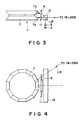
- Figure 3 is a front view of the first embodiment (a view in the cross-section thereof in the sub-scanning direction), and Figure 4 is a plan view thereof (a view in the scanning cross section).
- the scanning cross-section refers to a light beam surface which a light beam deflected and scanned by the deflecting reflecting surface of a rotatable polygonal mirror which is a deflector forms with the lapse of time.
- the sub-scanning cross-section refers to a cross-section perpendicular to the scanning cross-section and containing the optic axis of an f ⁇ lens.
- the scanning optical apparatus 1 comprises chiefly a semiconductor laser 3 as a light source emitting a laser beam LB, a collimator lens 5 for collimatng the laser beam LB incident from the semiconductor laser 3, a roof type rotatable polygonal mirror 7 having a plurality of pairs of mirror surfaces each formed by two reflecting surfaces 7a and 7b inclined inwardly and orthogonal to each other, a fixed reflecting mirror 9 disposed in opposed relationship with the reflecting surface 7b and comprising a plane mirror, a quarter wavelength plate ( ⁇ /4 plate) 11 disposed in opposed relationship with the reflecting surface 7a and delaying the phase by ⁇ /2 depending on the direction of polarization of the incident laser beam, and a polarizing beam splitter 13 disposed opposite to the roof type rotatable polygonal mirror 7 with the ⁇ /4 plate 11 interposed therebetween.
- a semiconductor laser 3 as a light source emitting a laser beam LB
- a collimator lens 5 for collimatng the laser beam LB incident from the semiconduct
- the laser beam LB impinges on one reflecting surface 7a of the roof type rotatable polygonal mirror 7 and is reflected thereby and impinges on the other reflecting surface 7b and is further reflected thereby, whereby the laser beam travels in the direction opposite to the direction in which it impinges on one reflecting surface 7a (in the cross-section of Figure 3, the incident light onto the reflecting surface 7a and the reflected light from the reflecting surface 7b are parallel to each other).
- the laser beam is reflected back by the fixed reflecting mirror 9 disposed so as to intersect the direction of travel of the laser beam and again impinges on said reflecting surface 7b (in the cross-section of Figure 3, the reflected light from the reflecting surface 7b and the re-incident light onto the reflecting surface 7b are on the same optical path), and again passes through the ⁇ /4 plate 11, following the optical path of the reflecting surface 7b ⁇ the reflecting surface 7a ⁇ the ⁇ /4 plate 11 (in the cross-section of Figure 3, the incident light onto the reflecting surface 7a and the re-reflected light from the reflecting surface 7a assume the same optical path).
- the laser beam which is circularly polarized light is converted into rectilinearly polarized light whose plane of polarization is perpendicular to the rectilinearly polarized light during incidence, and now passes rectilinearly through the polarizing beam splitter 13, and passes through an f ⁇ lens (not shown) and is imaged on a photosensitive drum (not shown) which is a surface to be scanned.
- the light beam from the light source and the light beam from the deflector are separated from each other by the use of the ⁇ /4 plate and the polarizing beam splitter.
- the roof type rotatable polygonal mirror 7 is rotated, whereby the beam LB transmitted through the polarizing beam splitter 13 is scanned in the scanning cross-section by uniform speed circular motion, and is converted into uniform speed rectilinear motion by the f ⁇ lens and scanned on the photosensitive drum.
- the fixed reflecting mirror 9 is disposed in opposed relationship with one reflecting surface 7b of the roof type rotatable polygonal mirror 7 and the beam LB reflected by the two reflecting surfaces 7a and 7b of the roof type rotatable polygonal mirror 7 and impinging on the fixed reflecting mirror 9 is turned back by the fixed reflecting mirror 9 so as to be again reflected by the two reflecting surfaces 7a and 7b and therefore, the scanning angle of the laser beam LB widens to twice as compared with that in the example of the prior art shown in Figure 1.
- the roof type rotatable polygonal mirror 7 can be made small in its outer diameter and compact and therefore, high-speed rotation of the roof type rotatable polygon mirror 7 becomes possible and high-speed scanning of the beam LB becomes possible. Or it is possible to increase the number of mirror surfaces even for the same size of the roof type rotatable polygonal mirror, and it becomes possible to scan the beam LB at a higher speed without increasing the rotational speed of the polygonal mirror.
- a plane mirror of one-piece construction is employed as the fixed reflecting mirror 9 and the polarizing beam splitter 13 is disposed on the side opposite to the roof type rotational polygonal mirror 7 with the ⁇ /4 plate 11 interposed therebetween, whereby the light beam produced from the semiconductor laser 3 can be used efficiently and design is made such that the forward path of the polarizing beam splitter 13 ⁇ the roof type rotatable polygonal mirror 7 ⁇ the fixed reflecting mirror 9 ⁇ and the backward path of the fixed reflecting mirror 9 the roof type rotatable polygonal mirror 7 ⁇ the polarizing beam splitter 13 ( ⁇ the f ⁇ lens) assume the same optical path in the cross-section in the sub-scanning direction shown in Figure 3 and therefore, the curvature of the scanning line resulting from the widening of the scanning angle of the beam and the fluctuation of the spot diameter of the beam LB do not occur as do in the example shown in Figure 2. Therefore, the reflecting surfaces 7a and 7b can be made large enough and the F-number of the
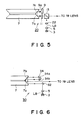
- FIG. 5 shows the construction of the second embodiment in the cross-section thereof in the sub-scanning direction.
- the construction of the scanning optical apparatus 20 is such that a cylindrical lens 22 disposed between the collimator lens 5 and the polarizing beam splitter 13 is added to the same optical construction as the first embodiment.
- This cylindrical lens 22 has power only in the sub-scanning direction which is a direction perpendicular to the scanning cross-section, and causes a parallel light beam LB incident from the collimator lens 5 to be imaged in the form of a line on the fixed reflecting mirror 9.
- the fixed reflecting mirror 9 and the imaging surface on the photosensitive drum are in a conjugate relationship with each other in the cross-section in the sub-scanning direction by an f ⁇ lens being disposed between the two. Therefore, even if the reflecting surface 9a of the fixed reflecting mirror 9 is not orthogonal to the incident laser beam LB in the cross-section in the sub-scanning direction and has more or less angle error, the pitch irregularity on the imaging surface of the photosensitive drum and the bending of the scanning line can be corrected.
- FIG. 6 shows the construction of the third embodiment in the cross-section in the sub-scanning direction.
- the construction of the scanning optical apapratus 30 is the same as that of the first embodiment with respect to the semiconductor laser 3, the collimator lens 5 and the roof type rotatable polygonal mirror 7, but instead of the polarizing beam splitter in the first embodiment, a plane reflecting mirror 32 is disposed at an angle of 45° with respect to the beam LB rectilinearly travelling from the collimator lens 5, and in place of the fixed reflecting mirror comprising a plane mirror, there is disposed a roof type fixed reflecting mirror 34 having two reflecting surfaces 34a and 34b orthogonal to each other.
- the laser beam LB is reflected by the two reflecting surfaces 34a and 34b of the roof type fixed reflecting mirror 34 disposed in the direction of travel of the light beam and is turned back, assuming an optical path parallel to the incidence optical path in the cross-section in the sub-scanning direction with a predetermined width (a matter of the reflection points of the reflecting surfaces 34a and 34b).
- the third embodiment is designed such that by the roof type fixed reflecting mirror 34 being disposed in opposed relationship with one reflecting surface 7b of the roof type rotatable polygonal mirror 7, the laser beam LB emerges from the roof type rotatable polygonal mirror 7 onto the f ⁇ lens, assuming an optical path parallel to the optical path along which the laser beam LB has impinged on the roof type rotatable polygonal mirror 7, but more toward the roof type fixed reflecting mirror 34 by a predetermined width, and therefore the polarizing beam splitter and the ⁇ /4 plate become unnecessary and the optical system can be simplified.
- roof type fixed reflecting mirror 34 is employed as the fixed reflecting mirror, it is not necessary to effect the correction of fall by a cylindrical lens as in the second embodiment.
- the scanning optical apparatus of the present invention is a scanning optical apparatus in which a light beam emitted from a light source is reflected by the mirror surfaces of a rotatable polygonal mirror and thereby deflected and scanned and wherein each mirror surface of said rotatable polygonal mirror comprises a pair of reflecting surfaces inclined toward the center of rotation of the rotatable polygonal mirror and orthogonal to each other and a reflecting mirror having at least one reflecting surface for reflecting the light beam from one of the pair of reflecting surfaces and returning said light beam to said one reflecting surface is fixed in opposed relationship with said one reflecting surface.
- design is made such that a fixed reflecting mirror is disposed in opposed relationship with one of the pairs of reflecting surfaces of the rotatable polygonal mirror and the beam which has impinged from said one reflecting surface onto the fixed reflecting surface is turned back and caused to impinge on the rotatable polygonal mirror again, whereby the light beam incident from the light source onto the rotatable polygonal mirror emerges from the rotatable polygonal mirror along an optical path parallel to the incidence optical path in the cross-section in the sub-scanning direction, and therefore it is possible to widen the scanning angle of the light beam to twice and yet prevent the curvature of the scanning line and the fluctuation of the diameter of the imaged spot which would result from the widening of the scanning angle.
- the rotatable polygonal mirror can be made compact and high-speed rotation of the rotatable polygonal mirror becomes possible and thus, high-speed scanning of the light beam becomes possible.
- the number of the mirror surfaces of the rotatable polygonal mirror can be increased even for the same size of the rotatable polygonal mirror, and higher-speed scanning of the light beam becomes possible without the rotational speed of the rotatable polygonal mirror being increased.
- the reflecting surfaces of the polygonal mirror can be made relatively large and therefore, the F-number of the beam can be made small and the diameter of the imaged spot of the light beam can be made small enough, and images of high quality can be recorded.
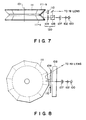
- Figure 7 shows the state of a fourth embodiment of the scanning optical apparatus of the present invention in the cross-section thereof in the sub-scanning direction
- Figure 8 is a view of the same embodiment in the scanning cross-section thereof
- Figure 9 shows the construction of a quarter wavelength plate shown in Figure 7.
- the reference numeral 100 designates light source means having, for example, a semiconductor laser or a polarizing plate and a light source for emitting predetermined rectilinearly polarized light.
- the light beam emitted from the light source 100 is a rectilinearly polarized beam.
- the reference numeral 102 denotes a collimator lens which collimates the light beam emitted from the light source 100.
- the reference numeral 107 designates a cylindrical lens having predetermined refractive power with respect to the sub-scanning cross-section.
- the reference numeral 108 denotes a polarizing beam splitter having the function of separating the incident light beam into two light beams by the use of double-refractive crystal.
- the reference numeral 109 designates a quarter wavelength plate formed by a plurality of crystals cemented together in such a manner that their crystal axes are orthogonal to one another and inclinedly disposed so that the crystal axes may form 45° with respect to the scanning direction of the light beam.
- the quarter wavelength plate 109 is formed by two crystal plates 109a and 109b being cemented together.
- the polarizing beam splitter 108 and the quarter wavelength plate 109 together constitute optical path separating means 120.
- the reference numeral 111 denotes a roof type rotatable polygonal mirror comprising a plurality of pairs of reflecting surfaces each pair comprising two reflecting surfaces 111a and 111b disposed at right angles in opposed relationship with each other, said plurality of pairs of reflecting surfaces being arranged around a rotational axis 101.
- the rotatable polygonal mirror 111 has twenty reflecting surfaces (ten pairs of reflecting surfaces) in total.
- the reference numeral 110 designates reflecting means comprising a fixed reflecting mirror having at least one reflecting surface. The reflecting means 110 is disposed in opposed relationship with the roof type rotatable polygonal mirror 111.
- the light beam emitted from the light source 100 is collimated by the collimator lens 102, is condensed in one-dimensional direction (the sub-scanning direction) by the cylindrical lens 107 and enters the polarizing beam splitter 108.
- Design is made such that the rectilinearly polarized light beam transmitted through the polarizing beam splitter enters the quarter wavelength plate 109 so that the direction of polarization of said light beam may be 0° or 90° with respect to the crystal axis of the quarter wavelength plate.
- the rectilinearly polarized light beam is converted into circularly polarized light by passing through the quarter wavelength plate 109 and impinges on the reflecting surface 111a of the roof type rotatable polygonal mirror 111, and is reflected upwardly as viewed in Figure 7 by the reflecting surface 111a and impinges on the other reflecting surface 111b.
- the incident light beam further reflected toward the fixed reflecting mirror 110 by the reflecting surface 111b is reflected by this fixed reflecting mirror 110 and becomes circularly polarized light opposite in direction to the direction during the incidence, and again impinges on the reflecting surface 111b, and emerges from the roof type rotatable polygonal mirror 111 along an optical path converse to that during the aforementioned incidence and again enters the quarter wavelength plate 109.
- the emergent light beam is converted into rectilineary polarized light whose plane of polarization is orthogonal to that during the incidence by the quarter wavelength plate 109 and enters the polarizing beam splitter 108, and is reflected upwardly as viewed in Figure 7 by this polarizing beam splitter 108 and is converged into the form of a spot on the surface of a photosensitive drum by an imaging optical system such as an f ⁇ lens, not shown.
- the roof type rotatable polygonal mirror 111 is rotated at a predetermined speed, whereby the surface of the photosensitive drum is optically scanned by the beam.
- the polarizing beam splitter 108 and the quarter wavelength plate 109 formed by two crystal plates being cemented together are used as the optical path separating means 120 for separating the optical paths of the incident light beam and emergent light beam from each other, whereby the light beam emitted from the light source 100 is efficiently directed to the surface of the photosensitive drum with the loss of the quantity of light of the light beam being reduced.
- an optically scanned light beam enters a quarter wavelength plate at an angle.
- the plate thickness d is (2m + 1) x 18.9 ( ⁇ m).
- the plate thickness d is as small as the order of 18.9 ⁇ m, and this becomes considerably difficult in manufacturing and holding.
- the integer m is given any value and the plate thickness d is adjusted so as to be of the order of 1 mm.
- the phase difference off the axis deviates by 0.9668 ⁇ ⁇ ⁇ as compared with that on the axis, and it is difficult to separate the light beam off the axis.
- the difference between the quantity of light on the axis and the quantity of light off the axis be set to the order of several %, and from this, the allowable phase difference off the axis is 0.0125 ⁇ or less and the plate thickness d is 12.9 ⁇ m or less when the difference is quantity of light is e.g. 5%.
- the quarter wavelength plate thus formed be applied to a scanning optical apparatus such as a laser printer.
- the quarter wavelength plate is effectively formed by two crystal plates being cemented together, thereby solving the aforementioned problem.
- the scanning direction is set so as to form an angle of 45° with respect to the crystal axis of the quarter wavelength plate
- the difference between the thicknesses of the two crystal plates 109a and 109b is set in such a manner as to provide a phase of ⁇ /4, i.e., to ⁇ /4 ⁇ n, even if the thickness d is commonly added to the plate thicknesses of the respective crystal plates, the optical path difference will not vary throughout the entire angle of field and the quarter wavelength plate can be set to any thickness for which manufacturing and holding is easy.
- the quarter wavelength plate thus formed becomes well applicable to a scanning optical apparatus such as a laser printer.
- two crystal plates are cemented together to form a quarter wavelength plate, whereby the quarter wavelength plate is relatively good in the manufacturing property and holding property thereof and the incident light beam and the emergent light beam can be accurately separated from each other.
- crystal equivalent to ⁇ /4 can likewise be cemented to the surface of a conventional glass substrate free of the double refractive property to thereby provide a quarter wavelength plate equal in performance to the aforedescribed quarter wavelength plate.
- the fourth embodiment of the present invention is a scanning optical apparatus in which a rectilinearly polarized light beam emitted from light source means is passed through a quarter wavelength plate by way of a polarizing beam splitter and is made into circularly polarized light thereby, is reflected by a pair of reflecting surfaces of a roof type rotatable polygonal mirror comprising a plurality of pairs of reflecting surfaces provided around a rotatable member, each said pair of reflecting surfaces comprising two reflecting surfaces disposed in opposed relationship with each other so as to be orthogonal to each other, and then is reflected by fixed reflecting means disposed in opposed relationship with said roof type rotatable polygonal mirror, and thereafter is returned to said roof type rotatable polygonal mirror and is again reflected by said pair of reflecting surfaces, and is caused to again enter said polarizing beam splitter as rectilinearly polarized light whose directions of polarization are orthogonal to each other when the light beam enters through said quarter wavelength plate, and the light beam caused
- the fourth embodiment of the present invention is characterized in that when the light beam emitted from said light source means enters said quarter wavelength plate, the direction of polarization of said light beam forms an angle of 0° or 90° with respect to the crystal axes of said crystals.
- a scanning optical apparatus having a roof type rotatable polygonal mirror and a fixed reflecting mirror and in which a polarizing beam splitter and a quarter wavelength plate are used as optical path separating means for separating the optical paths of the incident light beam and the emergent light beam from each other, said quarter wavelength plate is formed by a plurality of crystals cemented together so that the crystal axes thereof may be orthogonal to each other and is disposed so that said crystal axes may be at 45° with respect to the scanning direction, whereby the scanning optical apparatus is great in plate thickness and good in working property and suffers little from the retardation resulting from polarization in the entire angle of field and can alleviate the loss of the quantity of light.
- Figure 10 is a view showing the construction of a fifth embodiment of the scanning optical apparatus of the present invention in the sub-scanning cross-section thereof.
- the fifth embodiemnt proposes a scanning optical apparatus which, as shown in Figure 10, uses a beam splitter (a half mirror) as optical path separating means for separating the optical paths of the incident light beam and the emergent light beam from each other.
- a beam splitter a half mirror
- a rectilinearly polarized light beam emitted from a light source 71 is transmitted through a half mirror 75 and impinges on the reflecting surface 73a of a roof type rotatable polygonal mirror 73.
- the incident light beam is then reflected an odd number of times by the roof type rotatable polygonal mirror 73 and a fixed reflecting mirror 74, and again enters the half mirror 75.
- the light beam which has again entered the half mirror 75 is reflected upwardly as viewed in Figure 10 by the half mirror 75 and forms the image of image information on a photosensitive drum which is a surface to be scanned, by an f ⁇ lens, not shown.
- a scanning optical apparatus has a light source for emitting a light beam, and a deflector such as rotatable polygonal mirror having a plurality of mirror surfaces for deflecting the light beam emitted from the light source.
- a deflector such as rotatable polygonal mirror having a plurality of mirror surfaces for deflecting the light beam emitted from the light source.
- Each mirror surface of the rotatable polygonal mirror has a pair of reflecting surfaces inclined toward the center axis of rotation of the polygonal mirror and orthogonal to each other.
- a fixed reflecting mirror is arranged in opposed relationship with one of the pair of reflecting surfaces so that the light beam deflected by the deflector is reflected to be returned to the deflector again.
Landscapes
- Physics & Mathematics (AREA)
- General Physics & Mathematics (AREA)
- Optics & Photonics (AREA)
- Laser Beam Printer (AREA)
- Facsimile Scanning Arrangements (AREA)
- Mechanical Optical Scanning Systems (AREA)
Applications Claiming Priority (4)
| Application Number | Priority Date | Filing Date | Title |
|---|---|---|---|
| JP27465489A JPH03136017A (ja) | 1989-10-20 | 1989-10-20 | 走査光学装置 |
| JP274654/89 | 1989-10-20 | ||
| JP17806790A JP2687690B2 (ja) | 1990-07-05 | 1990-07-05 | 走査光学装置 |
| JP178067/90 | 1990-07-05 |
Publications (3)
| Publication Number | Publication Date |
|---|---|
| EP0423812A2 true EP0423812A2 (fr) | 1991-04-24 |
| EP0423812A3 EP0423812A3 (en) | 1991-12-04 |
| EP0423812B1 EP0423812B1 (fr) | 1995-04-19 |
Family
ID=26498375
Family Applications (1)
| Application Number | Title | Priority Date | Filing Date |
|---|---|---|---|
| EP90120090A Expired - Lifetime EP0423812B1 (fr) | 1989-10-20 | 1990-10-19 | Dispositif de balayage optique |
Country Status (3)
| Country | Link |
|---|---|
| US (1) | US5187606A (fr) |
| EP (1) | EP0423812B1 (fr) |
| DE (1) | DE69018759T2 (fr) |
Cited By (6)
| Publication number | Priority date | Publication date | Assignee | Title |
|---|---|---|---|---|
| EP0710864A3 (fr) * | 1992-07-15 | 1996-05-29 | Fuji Photo Film Co Ltd | |
| US6587246B1 (en) | 1998-09-02 | 2003-07-01 | Qinetiq Limited | Scanning apparatus |
| EP1528424A1 (fr) * | 2003-10-31 | 2005-05-04 | Hewlett-Packard Development Company, L.P. | Dispositifs et méthodes de balayage optique |
| CN104423036A (zh) * | 2013-08-23 | 2015-03-18 | 株式会社理光 | 光扫描装置、图像形成装置以及车辆 |
| EP2853935A1 (fr) * | 2013-09-27 | 2015-04-01 | Nidec Corporation | Appareil de rotation de miroir |
| EP2985650A4 (fr) * | 2013-04-11 | 2016-11-30 | Konica Minolta Inc | Système optique de balayage et radar |
Families Citing this family (6)
| Publication number | Priority date | Publication date | Assignee | Title |
|---|---|---|---|---|
| US5828483A (en) * | 1993-11-23 | 1998-10-27 | Schwartz; Nira | Printing and inspection system using rotating polygon and optical fibers |
| US5850307A (en) * | 1994-09-23 | 1998-12-15 | Gerber Systems Corporation | Scanner system having a dual trace spinner |
| US5867298A (en) * | 1996-12-16 | 1999-02-02 | Eastman Kodak Company | Dual format pre-objective scanner |
| KR101808185B1 (ko) * | 2010-12-27 | 2018-01-19 | 삼성전자 주식회사 | 도광판, 이를 포함하는 백라이트유닛, 디스플레이장치 및 도광판 제조방법 |
| EP3203259A1 (fr) * | 2016-02-03 | 2017-08-09 | Konica Minolta, Inc. | Dispositif de détection d'objet de type à balayage optique |
| JP7193367B2 (ja) * | 2019-02-07 | 2022-12-20 | 川崎重工業株式会社 | ポリゴンミラー、導光装置及び光走査装置 |
Family Cites Families (16)
| Publication number | Priority date | Publication date | Assignee | Title |
|---|---|---|---|---|
| DE2630381C2 (de) * | 1975-07-07 | 1983-05-26 | Pioneer Electronic Corp., Tokyo | Optischer Leser |
| GB1569879A (en) * | 1975-12-13 | 1980-06-25 | Barr & Stroud Ltd | Radiation scanning system |
| US4284994A (en) * | 1979-07-30 | 1981-08-18 | Eikonix Corporation | Laser beam recorder |
| GB2097145B (en) * | 1981-03-31 | 1984-08-22 | Ferranti Ltd | Optical scanning system switching between fields of view |
| JPS5837616A (ja) * | 1981-08-29 | 1983-03-04 | Minolta Camera Co Ltd | 光ビ−ム走査装置 |
| US4509819A (en) * | 1981-11-12 | 1985-04-09 | Lincoln Laser Company | Optical beam pulse generator |
| SU1182470A1 (ru) * | 1984-01-13 | 1985-09-30 | Киевский Научно-Исследовательский И Конструкторский Институт Периферийного Оборудования | Многогранник развертывающей системы |
| US4720632A (en) * | 1985-01-25 | 1988-01-19 | Ricoh Co., Ltd. | Synchronizing light beam detector |
| US4715699A (en) * | 1985-01-28 | 1987-12-29 | Asahi Kogaku Kogyo Kabushiki Kaisha | Scanning optical system for laser beam printers |
| GB8523849D0 (en) * | 1985-09-27 | 1985-10-30 | Secr Defence | Rangefinders |
| JPS6298332A (ja) * | 1985-10-25 | 1987-05-07 | Hitachi Ltd | 光記録合金タブレツト |
| US5015096A (en) * | 1986-10-10 | 1991-05-14 | Kowalski Frank V | Method and apparatus for testing optical components |
| JPH01235915A (ja) * | 1988-03-16 | 1989-09-20 | Fujitsu Ltd | 撮像装置 |
| JP2629281B2 (ja) * | 1988-07-11 | 1997-07-09 | ミノルタ株式会社 | レーザ走査装置 |
| JPH02259617A (ja) * | 1989-03-30 | 1990-10-22 | Sony Corp | レーザビーム偏向装置 |
| US4960312A (en) * | 1989-10-10 | 1990-10-02 | Mahmoud Razzaghi | Compact high resolution high speed symmetrical scanning optics using multiple deflections |
-
1990
- 1990-10-17 US US07/598,965 patent/US5187606A/en not_active Expired - Lifetime
- 1990-10-19 EP EP90120090A patent/EP0423812B1/fr not_active Expired - Lifetime
- 1990-10-19 DE DE69018759T patent/DE69018759T2/de not_active Expired - Fee Related
Cited By (11)
| Publication number | Priority date | Publication date | Assignee | Title |
|---|---|---|---|---|
| EP0710864A3 (fr) * | 1992-07-15 | 1996-05-29 | Fuji Photo Film Co Ltd | |
| US6587246B1 (en) | 1998-09-02 | 2003-07-01 | Qinetiq Limited | Scanning apparatus |
| EP1528424A1 (fr) * | 2003-10-31 | 2005-05-04 | Hewlett-Packard Development Company, L.P. | Dispositifs et méthodes de balayage optique |
| US7142340B2 (en) | 2003-10-31 | 2006-11-28 | Hewlett-Packard Development Company, L.P. | Optical scanner apparatuses and optical scanning methods |
| EP2985650A4 (fr) * | 2013-04-11 | 2016-11-30 | Konica Minolta Inc | Système optique de balayage et radar |
| US10078132B2 (en) | 2013-04-11 | 2018-09-18 | Konica Minolta, Inc. | Scanning optical system and radar |
| US10989794B2 (en) | 2013-04-11 | 2021-04-27 | Konica Minolta, Inc. | Scanning optical system and radar |
| CN104423036A (zh) * | 2013-08-23 | 2015-03-18 | 株式会社理光 | 光扫描装置、图像形成装置以及车辆 |
| US9348134B2 (en) | 2013-08-23 | 2016-05-24 | Ricoh Company, Ltd. | Optical scanning unit, and apparatus including the optical scanning unit |
| EP2853935A1 (fr) * | 2013-09-27 | 2015-04-01 | Nidec Corporation | Appareil de rotation de miroir |
| CN104516106A (zh) * | 2013-09-27 | 2015-04-15 | 日本电产株式会社 | 镜旋转装置 |
Also Published As
| Publication number | Publication date |
|---|---|
| US5187606A (en) | 1993-02-16 |
| DE69018759T2 (de) | 1995-09-21 |
| DE69018759D1 (de) | 1995-05-24 |
| EP0423812B1 (fr) | 1995-04-19 |
| EP0423812A3 (en) | 1991-12-04 |
Similar Documents
| Publication | Publication Date | Title |
|---|---|---|
| US4796961A (en) | Multi-beam scanning optical system | |
| US5355244A (en) | Optical scanner for reducing shading | |
| US5223956A (en) | Optical beam scanners for imaging applications | |
| US4634232A (en) | Light source device for close spacing of two light beams | |
| US5025268A (en) | Optical scanning apparatus and asymmetrical aspheric scanning lens | |
| US5491578A (en) | Optics for passive scan angle doubling | |
| US5009472A (en) | Light scanning device with polarizing device to make light transmission more uniform | |
| EP0423812B1 (fr) | Dispositif de balayage optique | |
| US5481384A (en) | Deflector system which produces dual, oppositely directed scanning beams simultaneously or successively | |
| US5377036A (en) | Suppression of stray light reflections in a raster output scanner (ROS) using an overfilled polygon design | |
| US4796965A (en) | Optical scanning device | |
| JPH035562B2 (fr) | ||
| CA1328756C (fr) | Systeme de balayage polygonal a faisceaux multiples | |
| EP1183861B1 (fr) | Appareil d'enregistrement a tambour interne a faisceaux et longueurs d'ondes multiples | |
| US5134513A (en) | Scanning optical system | |
| JPS60233616A (ja) | 光学走査装置 | |
| US5278691A (en) | Symmetrical overfilled polygon laser scanner | |
| JPH05303049A (ja) | シェーディングを軽減した光走査装置 | |
| JPH09197310A (ja) | マルチビーム走査装置 | |
| JP3532324B2 (ja) | 光走査装置 | |
| JP3243013B2 (ja) | シェーディング補正機能をもつ光走査装置 | |
| EP1528424B1 (fr) | Dispositifs et méthodes de balayage optique | |
| JP3254312B2 (ja) | 光走査装置 | |
| JP2687690B2 (ja) | 走査光学装置 | |
| JP2970053B2 (ja) | 光走査装置 |
Legal Events
| Date | Code | Title | Description |
|---|---|---|---|
| PUAI | Public reference made under article 153(3) epc to a published international application that has entered the european phase |
Free format text: ORIGINAL CODE: 0009012 |
|
| 17P | Request for examination filed |
Effective date: 19901221 |
|
| AK | Designated contracting states |
Kind code of ref document: A2 Designated state(s): DE FR GB IT |
|
| PUAL | Search report despatched |
Free format text: ORIGINAL CODE: 0009013 |
|
| AK | Designated contracting states |
Kind code of ref document: A3 Designated state(s): DE FR GB IT |
|
| 17Q | First examination report despatched |
Effective date: 19930913 |
|
| GRAA | (expected) grant |
Free format text: ORIGINAL CODE: 0009210 |
|
| AK | Designated contracting states |
Kind code of ref document: B1 Designated state(s): DE FR GB IT |
|
| REF | Corresponds to: |
Ref document number: 69018759 Country of ref document: DE Date of ref document: 19950524 |
|
| ITF | It: translation for a ep patent filed | ||
| ET | Fr: translation filed | ||
| PLBE | No opposition filed within time limit |
Free format text: ORIGINAL CODE: 0009261 |
|
| STAA | Information on the status of an ep patent application or granted ep patent |
Free format text: STATUS: NO OPPOSITION FILED WITHIN TIME LIMIT |
|
| 26N | No opposition filed | ||
| REG | Reference to a national code |
Ref country code: GB Ref legal event code: IF02 |
|
| PGFP | Annual fee paid to national office [announced via postgrant information from national office to epo] |
Ref country code: FR Payment date: 20031003 Year of fee payment: 14 |
|
| PGFP | Annual fee paid to national office [announced via postgrant information from national office to epo] |
Ref country code: GB Payment date: 20031016 Year of fee payment: 14 |
|
| PGFP | Annual fee paid to national office [announced via postgrant information from national office to epo] |
Ref country code: DE Payment date: 20031030 Year of fee payment: 14 |
|
| PG25 | Lapsed in a contracting state [announced via postgrant information from national office to epo] |
Ref country code: GB Free format text: LAPSE BECAUSE OF NON-PAYMENT OF DUE FEES Effective date: 20041019 |
|
| PG25 | Lapsed in a contracting state [announced via postgrant information from national office to epo] |
Ref country code: DE Free format text: LAPSE BECAUSE OF NON-PAYMENT OF DUE FEES Effective date: 20050503 |
|
| GBPC | Gb: european patent ceased through non-payment of renewal fee |
Effective date: 20041019 |
|
| PG25 | Lapsed in a contracting state [announced via postgrant information from national office to epo] |
Ref country code: FR Free format text: LAPSE BECAUSE OF NON-PAYMENT OF DUE FEES Effective date: 20050630 |
|
| REG | Reference to a national code |
Ref country code: FR Ref legal event code: ST |
|
| PG25 | Lapsed in a contracting state [announced via postgrant information from national office to epo] |
Ref country code: IT Free format text: LAPSE BECAUSE OF NON-PAYMENT OF DUE FEES;WARNING: LAPSES OF ITALIAN PATENTS WITH EFFECTIVE DATE BEFORE 2007 MAY HAVE OCCURRED AT ANY TIME BEFORE 2007. THE CORRECT EFFECTIVE DATE MAY BE DIFFERENT FROM THE ONE RECORDED. Effective date: 20051019 |