EP0423854A1 - Méthode pour déterminer l'alignement faux dans l'horizontale de parties allongées d'une machine, comme des cylindres et des rouleaux et instrument optique à réflexion apte à être utilisé dans cette méthode - Google Patents
Méthode pour déterminer l'alignement faux dans l'horizontale de parties allongées d'une machine, comme des cylindres et des rouleaux et instrument optique à réflexion apte à être utilisé dans cette méthode Download PDFInfo
- Publication number
- EP0423854A1 EP0423854A1 EP90202460A EP90202460A EP0423854A1 EP 0423854 A1 EP0423854 A1 EP 0423854A1 EP 90202460 A EP90202460 A EP 90202460A EP 90202460 A EP90202460 A EP 90202460A EP 0423854 A1 EP0423854 A1 EP 0423854A1
- Authority
- EP
- European Patent Office
- Prior art keywords
- line
- angle
- machine part
- imaginary
- far
- Prior art date
- Legal status (The legal status is an assumption and is not a legal conclusion. Google has not performed a legal analysis and makes no representation as to the accuracy of the status listed.)
- Withdrawn
Links
- 238000000034 method Methods 0.000 title claims abstract description 57
- 230000003287 optical effect Effects 0.000 title claims abstract description 36
- 238000005259 measurement Methods 0.000 claims abstract description 49
- 229910010293 ceramic material Inorganic materials 0.000 claims description 4
- 239000000696 magnetic material Substances 0.000 claims description 4
- 230000002093 peripheral effect Effects 0.000 claims description 2
- 230000001154 acute effect Effects 0.000 description 10
- 230000000295 complement effect Effects 0.000 description 4
- 238000006073 displacement reaction Methods 0.000 description 4
- 238000007792 addition Methods 0.000 description 1
- 238000012986 modification Methods 0.000 description 1
- 230000004048 modification Effects 0.000 description 1
- 238000002360 preparation method Methods 0.000 description 1
Images




Classifications
-
- G—PHYSICS
- G01—MEASURING; TESTING
- G01B—MEASURING LENGTH, THICKNESS OR SIMILAR LINEAR DIMENSIONS; MEASURING ANGLES; MEASURING AREAS; MEASURING IRREGULARITIES OF SURFACES OR CONTOURS
- G01B11/00—Measuring arrangements characterised by the use of optical techniques
- G01B11/26—Measuring arrangements characterised by the use of optical techniques for measuring angles or tapers; for testing the alignment of axes
Definitions
- the invention relates to a method for determining from optical measurement a numerical measure of the deviation in the horizontal plane between the actual and the desired position of elongated parts of a machine, which parts are disposed rotatably adjacent to each other with their axis at an angle to the longitudinal axis of the machine, using an imaginary vertical reference plane as far as possible lying at a distance from the machine, which reference plane is determined by two base points lying a distance apart which set up an imaginary base line which is removed from and can be situated at an angle relative to the longitudinal axis of the machine, and by an optically reflecting device having a reflecting surface disposed in such a way that any cross-section thereof with a horizontal plane is a straight line which forms, as far as possible, a right angle with the imaginary reference plane, while an optical measuring instrument is disposed in line with the axis of the machine part concerned, or in line with an imaginary line as far as possible parallel to said axis, which measuring instrument is taken into a first position in which its optically operative side is directed towards the optically reflecting device
- the telescope of viewer thereof is directed from its first position towards the machine part concerned in such a way that the line of sight forms a right angle with the imaginary reference plane.
- a measuring tab is placed as far as possible horizontally and at right angles to the axis of the machine part concerned, or an imaginary line as far as possible parallel to said axis, such as, for example, a generating line of the roller surface.
- the measuring tab is then placed near the other end of the machine part concerned, horizontally and at right angles to the axis, or to the imaginary line as far as possible parallel thereto, following which the apparent distance between the selected measuring point of the measuring tab and the vertical cross-wire of the telescope is determined again.
- the difference between the two measured distances is now a measure of the deviation in the horizontal plane between the actual position and the desired position of the machine part concerned.
- the measuring tab is in practice provided with different measuring points situated at known intervals, because in the case of a relatively large misalignment the distance to the initially selected measuring point can be too great to still be measured with a plane-parallel plate.
- the object of the invention is now in the first instance to improve the known method mentioned in the preamble in such a way that it is no longer necessary to carry out a measurement at both ends of a particular machine part, but that the measurement can be made at any easily reached and readily accessible point of a machine part.
- an optical or electro-optical measuring instrument equipped for angle measurement, a further optically reflecting device having a further reflecting surface being placed on the machine part concerned such that, the further reflecting surface faces the measuring instrument in a position wherein any cross-section of the further reflecting surface with a horizontal plane sets up a straight line of intersection which crosses or intersects the axis of the machine part concerned, or an imaginary line as far as possible parallel thereto, at the same included angle, and the measuring instrument is taken into a second position in which the optically operative side thereof is directed towards the further reflecting surface, such that the line of sight forms, as far as possible, a right angle with the line of intersection, an angle between the line of sight in the second position of the measuring instrument and an arbitrary imaginary line forming an angle with the imaginary reference plane being measured, by means of which measured angle and one or more of the other angles a numerical measure of the misalignment, i.e. deviation in the horizontal plane between the desired and the actual position, of the machine part concerned can be determined.
- the misalignment of the machine part is determined from a distance measurement
- the misalignment is determined by angle measurement.
- the angle between the imaginary base line and the longitudinal axis of the machine and also the included angle of the further optically reflecting surface with the axis of the machine part, or an imaginary line as far as possible parallel to said axis, and the angle between the imaginary reference plane and the arbitrary imaginary line relative to which the angle of the line of sight in the second position of the measuring instrument is measured are known, for example fixed, the misalignment angle between the axis of the machine part concerned and the longitudinal axis of the machine can be determined by means of a simple goniometrical relation with the aid of said known angles and the measured angle.
- the relative deviation of one end to the other end of the machine part concerned, with respect to its desired position measured transversely to the machine part or parallel to the longitudinal axis of the machines, can then be determined on the basis of this misalignment angle and the length of the machine part concerned.
- a further advantage of the method according to the invention lies in the fact that, with the current optical, in particular electro-optical, measuring instruments, angle measurements can be carried out more accurately than distance measurements. Compared with the known method, more accurate results can consequently be achieved more easily with the method according to the invention.
- a simplification of the determination of the abovementioned misalignment angle from the measured angle is obtained in a further embodiment of the method according to the invention through the fact that the imaginary base line is placed as far as possible parallel to the longitudinal axis of the machine, and the arbitrary imaginary line is selected as far as possible at right angles or as far as possible parallel to the imaginary base line, while the further optically reflecting device with its further reflecting surface is placed in such a position on the machine part concerned that the abovementioned line of intersection crosses or intersects the axis of the machine part concerned, or an imaginary line parallel to said axis, at an included angle which is as far as possible a right angle.
- the acute angle between said arbitrary imaginary line and the line of sight is equal to the misalignment angle. If the relevant arbitrary imaginary line is selected at right angles to the reference plane, the acute angle which the line of sight of the measuring instrument in the second position forms with said arbitrary imaginary line is equal to the complement of the misalignment angle.
- the misalignment direction of the machine part concerned can be determined by a suitable sign agreement from the sign preceding the measured angle.
- this is achieved through the fact that in order to place the further reflecting surface at an included angle which is as far as possible a right angle on a machine part to be measured, the position or misalignment of a machine part with known position or misalignment is determined by measuring under the assumption of an included right angle, after which the position or misalignment thus determined is compared with the known position or misalignment and, if there is an undesirable deviation, the position of the further reflecting surface is adapted by altering the abovementioned included angle, the steps of measuring, determining, comparing and adapting being repeated until the determined position or misalignment as far as possible corresponds to the known position or misalignment, in which case the further optically reflecting device with its further reflecting surface is set in such a way that on placing on a machine part to be measured the abovementioned line of intersection crosses or intersects the axis thereof or an imaginary line as far as possible parallel to said axis at an included angle which as far as possible is
- Said known position or misalignment can be determined by, for example, the method known from the abovementioned American Patent Specification.
- the misalignment angle in the horizontal plane of the other parts of the machine can be measured with a desired accuracy.
- the further optically reflecting device is placed on the machine part to be measured in a further position rotated about the axis of the machine part concerned relative to the abovementioned one position, such that the further reflecting surface faces the measuring instrument and any cross-section thereof with a horizontal plane sets up a further straight line of intersection which crosses or intersects the axis of the machine part concerned, or an imaginary line as far as possible parallel thereto, as far as possible at the same included angle as the angle of the line of intersection in the one position, and the measuring instrument is taken into a third position in which the optically operative side thereof is directed towards the further reflecting surface such that and the line of sight forms as far as possible a right angle with the further line of intersection, and a further angle between the line of sight in the third position of the measuring instrument and a further arbitrary imaginary line forming an angle with the imaginary reference plane being measured, with the aid of said angles in the one and
- the included angle which the one and the further line of intersection of the further reflecting surface in the horizontal position thereof forms with the axis of the machine part concerned, or an imaginary line as far as possible parallel to said axis, for example a generating line, can be eliminated from the measured results with the reflecting device in the one and the further position.
- this embodiment of the method according to the invention requires two measurements on a particular machine part, the time taken in adjusting the further reflecting surface of the further optically reflecting device in this way to the machine part concerned is saved. Both measurements can be carried out at an easily accessible place on the machine part concerned.
- the two measurements can be carried out from one and the same position thereof. In some cases it will, however, be necessary to move the measuring instrument in the direction along the imaginary base line and if necessary bring the line of sight thereof into line with the imaginary reference plane.
- a simplification of the determination of the misalignment angle can be achieved from the measured angles through the imaginary base line being placed as far as possible parallel to the longitudinal axis of the machine, while the arbitrary imaginary lines relative to which the one and the further angle of the line of sight of the measuring instrument in the third position thereof are measured is selected as far as possible at right angles or as far as possible parallel to the imaginary base line.
- the arbitrary imaginary lines are situated in the imaginary reference plane, the misalignment angle is equal to half the sum of the measured acute angles. If the relevant arbitrary imaginary lines are selected at right angles to the reference plane, the complement of the misalignment angle is equal to half the sum of the measured acute angles.
- the direction in which the machine part concerned is out of line is determined by a suitable sign agreement from the sign preceding the sum concerned.
- the angle between a line and a plane is defined as the acute angle between said line and its projection perpendicular on said plane.
- the measurements have not necessarily be carried out in the horizontal plane.
- the measuring instrument may be positioned at different heights, provided its optical operative side can be drected towards the further reflecting surface. Measurements with the line of sight of the measuring instrument in a horizontal plane are rather exceptional.
- a further optically reflecting device provided with a flat mirror is essentially sufficient for carrying out the method according to the invention.
- the theodolite is thereby brought into the abovementioned first, second or third position by autocollimation with the particular optically reflecting surface.
- autocollimation is understood to mean that in the telescope at least the image of the vertical cross-wire coincides with its mirror image coming from the reflecting surface concerned.
- the image of the point of intersection of the horizontal and vertical cross-wires in the telescope coincides with the mirror image thereof.
- a further optically reflecting device is placed on the machine part concerned, having a roof-shaped further reflecting surface made up of two flat reflecting surfaces standing at an aperture angle to each other and intersecting each other along a straight line.
- a measuring instrument comprising a (laser) light beam transmitter and receiver disposed above or below each other at its optically working side, as disclosed, for example, by US Patent Specification 4,709,485 or the International Patent Application WO-A-8,404,960, the use of a further reflecting device in the form of a so-called "roof mirror" is necessary.
- the further optically reflecting surface is a flat mirror, for example, the above-mentioned condition concerning the placing thereof on a machine part concerned such that any cross-section thereof with a horizontal plane sets up said one or further straight line of intersection which crosses or intersects the axis of the machine part concerned, or an imaginary line as far as possible parallel to said axis, at the same included angle, is automatically met.
- this can be achieved in that, in order to take the further reflecting surface into the position facing the measuring instrument, in which any cross-section thereof with a horizontal plane sets up a straight line of intersection which crosses or intersects the axis of the machine part concerned, or an imaginary line as far as possible parallel to said axis, at the same included angle, the further optically reflecting device is brought with its straight line into a position which is as far as possible horizontal, using a precision levelling instrument.
- the method in which measurements are carried out with the further optically reflecting device in the one position and the further position rotated through 200 gon (decimal degree system) relative thereto has the advantage that the misalignment of rotating machine parts can also be determined therewith, for which purpose, according to an embodiment of the method according to the invention, the further optically reflecting device is fixed on the machine part concerned with its reflecting surface facing the imaginary reference plane.
- Measuring on rotating machine parts is very profitable from the economic point of view, because it means that the period which a machine is at a standstill for the alignment of the machine parts can be shortened by at least the time taken for measuring the misalignment. Measuring on rotating machine parts also gives greater freedom in the time at which the misalignment measurement can be carried out.
- the further optically reflecting device is provided with a roof-shaped further reflecting surface, made up of two flat reflecting surfaces standing at an aperture angle to each other and intersecting each other along a straight line, and, through rotation of the machine part concerned, the further optically reflecting device is taken into the abovementioned one and further position, in which any cross-section of the further reflecting surface with a horizontal plane sets up a straight line of intersection, and the measuring instrument is brought into the abovementioned second and third positions by autocollimation with the further reflecting surface, in which positions the abovementioned one or further position of the further optically reflecting device is determined with the aid of the uninterrupted reflected image of the vertical cross-wire of the telescope coming from the further reflecting surface.
- the accuracy of the measurement can be improved by determining the angles to be measured for determining a numerical measure of the misalignment of the machine part concerned from the average of several partial measurements.
- the invention also relates to an optical reflection instrument suitable for use with the method according to the invention, which optical reflection instrument is made up of a carrier element, means for placing the carrier element on a part of a machine to be measured, an optically reflecting device which is disposed movably on the carrier element and having a reflecting surface, and means for adjusting the position of the reflecting device.
- the carrier element is provided with projecting legs, for placing on a machine part to be measured, at least one of the legs is made displaceable in the direction relative to the carrier element.
- the carrier element is elongated in shape, preferably made of ceramic material and having at least one flat face, near and along a long edge of which a projection is provided.
- a support extends from a face of the carrier element, having a rotatable shaft on which the optically reflecting device is fixed, while the means for adjusting the optically reflecting device into a desired position further comprise an annular element to be fixed on the shaft and provided with a lip projecting outwards relative to its periphery, while the support is provided with two opposite lobes projecting in the same direction, in such a way that in the fitted state the lip of the annular element lies between the two lobes of the support, which two lobes are provided with means for varying the distance of the lip from the two lobes.
- the optically reflecting device is provided with a roof-shaped reflecting surface, made up of two flat reflecting surfaces which stand at an aperture angle to each other, and intersecting each other along a straight line. If a theodolite is used as the measuring instrument, such a roof mirror facilitates the setting of the telescope of the measuring instrument by autocollimation.
- said reflecting surface can be brought into the position facing the measuring instrument in which any cross-section with a horizontal plane sets up a straight line of intersection which crosses or intersects the axis of the machine part concerned, or an imaginary line as far as possible parallel to said axis, at the same included angle, by bringing the line of intersection of its two flat reflecting surfaces in the horizontal position.
- the optically reflecting device is made up of a holder on which the reflecting surface is mounted, said holder is provided with a levelling instrument.
- the levelling instrument is preferably a precision levelling instrument.
- the invention consequently also relates to an elongated machine part such as a cylinder or roller, characterized in that at least one optically reflecting device is fixed on one or both end faces thereof.
- the optically reflecting device is preferably provided with a roof-shaped reflecting surface, made up of two flat reflecting surfaces which stand at an aperture angle to each other and which intersect each other along a straight line. They can be either individual mirrors or, preferably, a prism of which two surfaces are made reflecting.
- the invention also relates to an elongated machine part having means for detecting the position in which the straight line of the roof-shaped reflecting surface is in the horizontal position.
- These means can be either optical or electronic.
- the invention also includes a machine having one or more elongated parts such as cylinders or rollers, which are provided having at least one optically reflecting device, for example with a roof-shaped reflecting surface and, if necessary, with means for detecting the horizontal position thereof.
- a machine having one or more elongated parts such as cylinders or rollers, which are provided having at least one optically reflecting device, for example with a roof-shaped reflecting surface and, if necessary, with means for detecting the horizontal position thereof.
- reference number 1 indicates a machine whose parts 2, in this case rollers, must be aligned in such a way that they come to lie as far as possible parallel to each other and at right angles to the longitudinal axis L, indicated by a dashed and dotted line, of the machine 1.
- the machine 1 can be, for example, a machine for paper preparation set up in a machine shop. Outside the machine 1, on the floor of the machine shop, two base points 3, 4, which set up an imaginary base line ⁇ , shown in Fig. 1 by a dashed and double dotted line, are marked on the floor of the machine shop.
- the base points 3, 4 are preferably made with as great as possible a distance between them, which can already be carried out, for example, when the machine 1 is being installed.
- an optically reflecting device 5 with a reflecting surface 6 is set up in such a way that any cross-section thereof with a horizontal plane is a straight line which crosses or intersects the base line ⁇ at, as far as possible, a right angle.
- the reflecting surface 6 now defines an imaginary reference plane ⁇ , which is shown partially in Fig. 1 hatched with dashed lines, and of which the imaginary base line ⁇ forms part. It will be clear that the reflecting surface 6, depending on its width in the direction at right angles to the imaginary base line ⁇ , defines a collection of parallel imaginary reference planes ⁇ .
- the reflecting surface 6 can be an ordinary flat mirror, but is preferably a roof-shaped reflecting surface, made up of two flat reflecting surfaces which stand at an aperture angle of, for example, 30 gon to 130 gon (decimal degree system) to each other and intersect each other along a straight line. Such a roof-shaped reflecting surface 6 defines a more extended imaginary reference plane ⁇ than a single flat mirror of the same dimensions.
- a reflecting device 5 can be used essentially for the alignment of all parts 2 of the machine 1.
- the reflecting device 5 can be made fixed or detachable, and if desired portable. In the last-mentioned case it must then be set up anew each time for carrying out a measurement on a machine.
- the setting-up of the reflecting device 5 can be, for example, carried out in such a way that an optical or electro-optical measuring instrument such as a theodolite is set up above the base point 4.
- a theodolite is generally made up of a stand with a telescope or viewer disposed movably thereon and provided with a horizontal and vertical cross-wire. Measuring instruments of this type are known per se in practice and need no further explanation.
- the reflecting device 5 is now adjusted in such a way that in the telescope the image of the vertical cross-wire and the mirror image thereof from the reflecting surface 6 coincide. In this position the reflecting surface 6 defines an imaginary reference plane ⁇ , as desired.
- the reflecting device 5 with its reflecting surface 6 is fixed in this position.
- an optical measuring instrument 7 in the form of a theodolite is set up in line with the axis M or an imaginary line m as far as possible parallel to said axis which, for example in the case of a roller, can be a generating line of the roller surface. All this is shown schematically in Fig. 2 in the horizontal plane, on an enlarged scale relative to Fig. 1.
- the imaginary base line ⁇ is for the time being selected so that it is parallel to the longitudinal axis L of the machine.
- the measuring instrument 7, in this case a theodolite is directed with its optically operative side 8, i.e. the telescope thereof, facing the optically reflecting device 5, the line of sight Z of the telescope being directed as far as possible parallel to the imaginary base line ⁇ or the imaginary reference plane ⁇ . From this first position I the telescope is rotated with its line of sight Z towards the machine part concerned, in such a way that it forms an angle which is as far as possible a right angle with the imaginary base line ⁇ or the imaginary reference plane ⁇ .
- a measuring tab 14 is then placed on the machine part 9 concerned at one end thereof, as far as possible horizontally and at right angles to the axis M thereof, and provided with one or more measuring points lying at known intervals. With the aid of a plane-parallel plate (not shown) fitted in front of the telescope, the apparent distance d1 in the direction parallel to the imaginary base line ⁇ between a specific measuring point MP on the measuring tab and the line of sight Z, i.e. the vertical cross-wire of the telescope is determined.
- the measuring tab 14 is then placed near the other end of the machine part 9 concerned and in the same way the distance d2 between said selected measuring point MP of the measuring tab 14 and the line of sight Z of the telescope is determined.
- the difference between the two measured distances d1 and d2 is a measure of the misalignment of the machine part 9 concerned.
- the misalignment measurement according to the state of the art is thus a distance measurement in the horizontal plane.
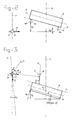
- Fig. 3 shows schematically, in the horizontal plane, an embodiment of the method according to the invention, in which the misalignment of a particular machine part 9 is determined by angle measurement. As the point of departure the most general situation is taken, in which the imaginary base line ⁇ forms an angle ⁇ with the longitudinal axis L of the machine.
- a further optically reflecting device 10 with a further reflecting surface 11 is placed on the machine part 9 concerned.
- This further optically reflecting device 10 is placed with its further reflecting surface 11 in such a position that any cross-section of the further reflecting surface 11 with a horizontal plane sets up a straight line of intersection X which crosses or intersects the axis M of the machine part 9 concerned or, for example, a generating line m of the surface of the machine part 9 concerned, as far as possible parallel to the axis M, at the same included angle ⁇ .
- the further optically reflecting device 10 has a flat reflecting surface 11, the abovementioned condition concerning the line of intersection X is automatically met. If, however, the further optically reflecting device 10 has a roof-shaped reflecting surface 11, comprising two reflecting surfaces 12 standing at an aperture angle ⁇ relative to each other and intersecting each other along a straight line s, as shown schematically in perspective in Fig. 4, the requirement concerning the line of intersection X is met only if the straight line s lies in the horizontal plane.
- a roof-shaped reflecting surface 11 can be brought with its abovementioned straight line s in the desired horizontal position using, for example, a precision levelling instrument.
- the measuring instrument 7 is now taken into a first position I, in which the line of sight Z of the measuring instrument 7 is directed as far as possible parallel to the imaginary base line ⁇ , or the imaginary reference plane ⁇ .
- the measuring instrument 7 is then taken into a second position II, in which its optically operative side 8 is directed towards the further reflecting surface 11, and the line of sight Z forms an angle which is as far as possible a right angle with the abovementioned line of intersection X.
- the misalignment angle ⁇ it is now important to know the angle between the line of sight Z of the measuring instrument 7 in the first position I and second position II. In the most general form this angle can be determined by measuring the angle ⁇ which the line of sight Z forms in the second position II with an arbitrary imaginary line ⁇ which in turn forms an angle ⁇ with the imaginary reference plane ⁇ .
- the absolute value of the misalignment angle ⁇ is equal to:
- ⁇ 100 gon
- the complement of the misalignment angle is equal to the measured acute angle ⁇ between the arbitrary imaginary line ⁇ and the line of sight Z of the measuring instrument 7 in the second position II thereof.
- the length 1 of the machine part 9 concerned can be used to determine the displacement d s in the horizontal plane in the direction along the longitudinal axis L of the machine, or the displacement d t in the horizontal plane at right angles to the axis M of the machine part concerned.
- d s 1 sin ⁇
- d t 1 tg ⁇ (4)
- the misalignment of a machine part can be determined by a single angle measurement, namely measuring the angle ⁇ , and making a simple goniometric calculation. It will be understood that the necessary goniometric calculations can be carried out automatically, for example using a microprocessor.
- the included angle ⁇ between the line of intersection X and the axis M of the machine part concerned, or an imaginary line m as far as possible parallel thereto is not known, it can be determined by measuring on a machine part with known position or misalignment.
- the known position or misalignment can, if necessary, be determined by the known method, as described with reference to Fig. 2.
- the included angle ⁇ can be determined or the position of the further optically reflecting device 10 can be adapted in such a way that the abovementioned included angle is as far as possible a right angle, i.e. 100 gon.
- Fig. 5 shows schematically a further embodiment of the method according to the invention, in which it is no longer necessary to know, for example, the included angle ⁇ .
- two individual measurements have to be carried out on the same machine part, but in practice this need not be a disadvantage because the further optically reflecting device 10 can be positioned here at a readily accessible place on the machine part concerned.
- a second, similar angle measurement is also carried out, but in this case the further optically reflecting device 10 is brought into a further position rotated relative to the first measurement through 200 gon about the axis M of the machine part 9 concerned.
- the position on the machine part concerned is not stipulated here.
- any cross-section of the further reflecting surface 11 with a horizontal plane sets up a further straight line of intersection X* which crosses or intersects the axis M of the machine part 9 concerned, or a line m as far as possible parallel to said axis, for example a generating line m of the surface, at a same included further angle ⁇ * as far as possible equal to the angle ⁇ of the line of intersection X in the first measurement.
- the measuring instrument 7 is now taken into a third position III, in which its optically operative side 8 is directed towards the further reflecting surface 11, and the line of sight Z forms an angle which is as far as possible a right angle ⁇ * with the further line of intersection X*.
- the size of the misalignment angle ⁇ can be determined from:
- the angles ⁇ , ⁇ and ⁇ * are known, the misalignment angle ⁇ can be calculated from (6), using the
- the direction in which the machine part 9 concerned is out of line can be determined from the sign preceding the sum concerned.
- the angle ⁇ for example, can also be eliminated from the equations (1) and (5), but then the included angles ⁇ and ⁇ * must be known, for example each 100 gon.
- the misalignment angle ⁇ of the machine part concerned can also be calculated from the double angle measurement if the angular position of the imaginary reference plane ⁇ relative to the longitudinal axis L of the machine is unknown.
- the measuring instrument 7 In the double angle measurement described with reference to Fig. 5 it is assumed that the measuring instrument 7 must be set up at two different positions, the measuring instrument 7 having to be adjusted by always taking it into the abovementioned first position I. This need not, however, always be necessary. Depending on the distance of the measuring instrument 7 from the machine part concerned, or the further optically reflecting device 10 placed thereon, and the dimensions thereof, it is possible in some cases to measure from one and the same position of the measuring instrument 7. In a similar way to that described with reference to Fig. 3, it is possible by means of equation (4) to calculate the misalignment in the horizontal plane, i.e. the distances d s and d t from the length of the machine part concerned and the misalignment angle determined.
- the double angle measurement is particularly suitable for measuring on rotating machine parts, as shown schematically in Figs. 6a and 6b.
- a further optically reflecting device 10 Fixed at one end of the machine part 9 concerned, on the end face thereof, is a further optically reflecting device 10, of which the reflecting surface faces in the direction towards the imaginary reference plane ⁇ or the imaginary base line ⁇ .
- the imaginary reference plane ⁇ runs parallel to the longitudinal axis L of the machine, and that the arbitrary imaginary lines ⁇ and ⁇ * lie at right angles to the reference plane, as shown.
- the two measured angles ⁇ and ⁇ * in the second position II and third position III respectively of the measuring instrument 7 will be equal in size, as illustrated in Fig. 6a.
- the relevant angles ⁇ an ⁇ * will, however, be different, as shown in Fig. 6b.
- the misalignment angle ⁇ of the machine part concerned can then again be calculated from the measured angles ⁇ and ⁇ *, as described in the above with reference to Fig. 5.
- the two measurements must be carried out when the further optically reflecting device 10 is in the position in which any cross-section of the further reflecting surface 11 thereof with a horizontal plane sets up a straight line of intersection X or X* which crosses or intersects the axis M of the machine part 9 concerned, or an imaginary line m which as far as possible is parallel to said axis, at the same included angle ⁇ or ⁇ *.
- two or more optically reflecting devices 10 can be fixed on the machine part concerned, if necessary. On account of accuracy requirements, in operating conditions it is preferable to use a single further optically reflecting device 10.
- the method according to the invention can be carried out either with an optical or electro-optical measuring instrument in the form of a theodolite, or with a measuring instrument equipped with a light beam transmitter and receiver, in particular laser light.
- a theodolite with a telescope provided with cross-wires is used, the telescope with its line of sight Z is taken into the abovementioned second position II and if necessary third position III by autocollimation of the vertical cross-wire with the further optically reflecting surface 11.
- Autocollimation is understood to mean that in the telescope the image of the vertical cross-wire coincides with the reflected image thereof received from the further optically reflecting surface 11.
- the further reflecting surface 11 can be an ordinary flat mirror, but it is preferably a roof-shaped reflecting surface 11, comprising two flat reflecting surfaces 12 with an aperture angle ⁇ of, for example, 30 gon to 130 gon (see Fig. 4).
- Such light beam transmitter/receiver combinations like optical or electro-optical theodolites, are available commercially.
- Certain embodiments of laser light beam transmitter/receiver combinations have a processing unit which can indicate the angle which the reflected light beam forms with the transmitted light beam. The half angle difference determines the position in which the line of sight Z of the measuring instrument forms a right angle with the reflecting surface concerned. This is important for determining, by the method according to the invention, the abovementioned second position II and, if necessary, third position III of the measuring instrument.
- a further optically reflecting device 10 with a roof-shaped reflecting surface 11 With the use of a further optically reflecting device 10 with a roof-shaped reflecting surface 11 the position in which any cross-section of the reflecting surface 11 with a horizontal plane sets up a straight line of intersection X or X* is obtained if the line of intersection s under which the individual flat reflecting surfaces 12 of such a roof-shaped reflecting surface 11 intersect each other lies horizontally.
- this position can be adjusted by means of a precision levelling instrument.
- the horizontal position thereof in other words the position in which the straight line s lies horizontally, can be indicated, for example, with separate optical or electronic means.
- the abovementioned horizontal position can be determined by means of the uninterrupted reflected image of the vertical cross-wire from the further reflecting surface 11.
- the horizontal position of a roof-shaped reflecting surface can be established by means of the absence of an angle difference between the transmitted and reflected beam in the vertical direction.
- the accuracy of the measurement can be improved by determining a numeric measure of the misalignment of the machine part concerned from several partial measurements.
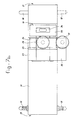
- Figures 7a, 7b and 7c show schematically a front, top and side view respectively of an embodiment of an optical reflection instrument for use with the method according to the invention for determining the misalignment of stationary machine parts described above.
- the reflection instrument is made up of an elongated rectangular carrier element 17. From a face of the carrier element 17 several legs 18 extend outwards, by means of which the carrier element can be placed on the surface of a machine part to be measured.
- a support 22, bearing an optically reflecting device 19 having an optically reflecting surface, extends from another face of the carrier element 17 in the direction at right angles to the legs 18.
- the legs 18 are arranged in pairs at each of the ends 20 and 21 of the carrier element 17.
- the optically reflecting device 19 is disposed at or as far as possible near the end 21.
- the legs 18 near the end 20 of the carrier element 17 are movable in the direction away from and towards the carrier element 17, such that the angle ⁇ (see Fig.
- the optically reflecting device 19 is provided with a roof-shaped reflecting surface comprising two flat reflecting surfaces 35, 36 standing at an aperture angle ⁇ to each other, which reflecting surfaces intersect each other along a straight line s 37, see also Fig. 4.
- the whole unit is fitted in a holder, which is provided with a levelling instrument 34 having a level tube positioned parallel with the straight line s.
- the support 22 is to this end provided with a rotatably mounted shaft 23 on which the optically reflecting device 19 is fixed.
- the annular element 24 is provided on the peripheral side with an internally threaded through hole 30 extending in the radial direction.
- the annular element 24 can be fixed on the shaft 23 by means of a locking screw 29 to be fitted in the hole 30. This means of fixing makes it possible to place the reflecting device 19 roughly in the desired position.
- Fine adjustment of this position is possible by rotating the annular element 24 through moving the lip 25 between the two lobes 26, 27.
- the lobe 26 is provided with an internally threaded through-hole 28, in which an adjusting screw 31 can be moved.
- the other lobe 27 is provided with spring means 32 acting on the lip 25, which spring means act on the lip 25 in the opposite direction to that of the adjusting screw 31.
- the position of the lip 25 between the two lobes 26, 27 can be altered through displacement of the adjusting screw 31.
- the carrier element 17 may be provided with further legs 18 at its face in front of and parallel with the face at which the legs 18, shown with solid lines, are arranged. This, in order to carry out the method according to the invention as illustrated in Fig. 4. With these further legs the angle ⁇ * can be adjusted.
- the elongated carrier element 17 is provided with flat faces 38, 39 for placing the carrier element on a machine part to be measured, respectively, for example a roller 9, as illustrated in Fig. 8.
- the faces 38, 39 can be made extremely flat.
- the elongated carrier element can be placed with its longitudinal axis as far as possible parallel with the axis of said machine part 9.
- the angles ⁇ and ⁇ * as illustrated in Fig. 4 are determined by the position of the reflecting device 19, i.e. its reflecting surface, with respect to said faces 38, 39.
- the reflecting surface of the reflecting device 19 is arranged at right angles to said faces 38, 39.
- the reflecting device 19 may be fixedly positioned on the carrier element, but is preferably adjustable in order to adjust said right angles, i.e. the angles ⁇ and ⁇ *.
- the faces 38, 39 are provided with projections 40, 41, extending in longitudinal direction of the carrier element, and having a square or rectangular cross-section. These projections 40, 41 serve as support edge for stably positioning the carrier element in tangential direction of a roller to be measured. It will be understood that for carrying out the measurement according to Fig. 3, a carrier element having one face 38, 39 and projection 40, 41 satisfies.
- the dimensions of the carrier element are approximately 50 cm in length, 6 cm in width and 6 cm in thickness.
- the projections 40 and 41 are approximately 1 cm width and 1 cm thick.
- the carrier element 17 can be provided with suitable clamp means or provided with means of permanent magnetic material.
- the legs 18 are preferably made of permanent magnetic material.
- the faces 38 and 39 may be provided with a strip of magnetic material or the like (not shown).
Landscapes
- Physics & Mathematics (AREA)
- General Physics & Mathematics (AREA)
- Length Measuring Devices By Optical Means (AREA)
Applications Claiming Priority (2)
| Application Number | Priority Date | Filing Date | Title |
|---|---|---|---|
| NL8902319 | 1989-09-15 | ||
| NL8902319A NL8902319A (nl) | 1989-09-15 | 1989-09-15 | Werkwijze voor het bepalen van de scheefstand in het horizontale vlak van langwerpige delen van een machine, zoals rollen en walsen, alsmede een voor toepassing bij deze werkwijze geschikt optisch reflectie-instrument. |
Publications (1)
| Publication Number | Publication Date |
|---|---|
| EP0423854A1 true EP0423854A1 (fr) | 1991-04-24 |
Family
ID=19855322
Family Applications (1)
| Application Number | Title | Priority Date | Filing Date |
|---|---|---|---|
| EP90202460A Withdrawn EP0423854A1 (fr) | 1989-09-15 | 1990-09-17 | Méthode pour déterminer l'alignement faux dans l'horizontale de parties allongées d'une machine, comme des cylindres et des rouleaux et instrument optique à réflexion apte à être utilisé dans cette méthode |
Country Status (3)
| Country | Link |
|---|---|
| US (1) | US5123736A (fr) |
| EP (1) | EP0423854A1 (fr) |
| NL (1) | NL8902319A (fr) |
Cited By (2)
| Publication number | Priority date | Publication date | Assignee | Title |
|---|---|---|---|---|
| WO2001046645A1 (fr) * | 1999-12-22 | 2001-06-28 | Armin Wiblishauser | Procede et dispositif pour l'alignement de corps |
| CN102628680A (zh) * | 2012-04-18 | 2012-08-08 | 中国十九冶集团有限公司 | 回转窑同心度测量方法及该方法中的基准线的确定方法 |
Families Citing this family (6)
| Publication number | Priority date | Publication date | Assignee | Title |
|---|---|---|---|---|
| US7113271B2 (en) * | 2003-05-07 | 2006-09-26 | Mark Vincent Loen | Method to accurately measure the angular orientation of a rotating axis to a reference line |
| US7171759B1 (en) | 2003-06-02 | 2007-02-06 | Mark Vincent Loen | Method and apparatus to accurately measure the angular orientation of two surfaces |
| US20070127011A1 (en) * | 2003-09-08 | 2007-06-07 | Loen Mark V | Method and Apparatus for Measuring the Angular Orientation Between Two Surfaces |
| US7312861B2 (en) * | 2003-09-08 | 2007-12-25 | Mark Vincent Loen | Method and apparatus for measuring the angular orientation between two surfaces |
| CN106052625B (zh) * | 2016-08-22 | 2018-11-30 | 中国十九冶集团有限公司南京分公司 | 测量筒体同心度的方法 |
| US12429322B2 (en) | 2022-03-15 | 2025-09-30 | Carlisle Construction Materials, LLC | Locating, measuring, and error-checking system |
Citations (4)
| Publication number | Priority date | Publication date | Assignee | Title |
|---|---|---|---|---|
| DE2026108A1 (de) * | 1969-05-29 | 1970-12-03 | Continental Oil Company, Ponca City, OkIa. (V.St.A.) | Verfahren und Vorrichtung zum optischen Ausrichten einer Maschinenanlage |
| US3726600A (en) * | 1971-10-06 | 1973-04-10 | Us Army | Off-axis alignment device |
| US3923402A (en) * | 1973-01-10 | 1975-12-02 | Beloit Corp | Method and apparatus for aligning paper machinery |
| US4003133A (en) * | 1973-05-21 | 1977-01-18 | Papierfabrieken Van Gelder Zonen N.V. | Method for the alignment of machine parts |
Family Cites Families (1)
| Publication number | Priority date | Publication date | Assignee | Title |
|---|---|---|---|---|
| US4298281A (en) * | 1979-07-16 | 1981-11-03 | Libbey-Owens-Ford Company | Laser system for aligning conveyor rolls |
-
1989
- 1989-09-15 NL NL8902319A patent/NL8902319A/nl not_active Application Discontinuation
-
1990
- 1990-09-17 EP EP90202460A patent/EP0423854A1/fr not_active Withdrawn
- 1990-09-17 US US07/583,431 patent/US5123736A/en not_active Expired - Fee Related
Patent Citations (4)
| Publication number | Priority date | Publication date | Assignee | Title |
|---|---|---|---|---|
| DE2026108A1 (de) * | 1969-05-29 | 1970-12-03 | Continental Oil Company, Ponca City, OkIa. (V.St.A.) | Verfahren und Vorrichtung zum optischen Ausrichten einer Maschinenanlage |
| US3726600A (en) * | 1971-10-06 | 1973-04-10 | Us Army | Off-axis alignment device |
| US3923402A (en) * | 1973-01-10 | 1975-12-02 | Beloit Corp | Method and apparatus for aligning paper machinery |
| US4003133A (en) * | 1973-05-21 | 1977-01-18 | Papierfabrieken Van Gelder Zonen N.V. | Method for the alignment of machine parts |
Cited By (3)
| Publication number | Priority date | Publication date | Assignee | Title |
|---|---|---|---|---|
| WO2001046645A1 (fr) * | 1999-12-22 | 2001-06-28 | Armin Wiblishauser | Procede et dispositif pour l'alignement de corps |
| CN102628680A (zh) * | 2012-04-18 | 2012-08-08 | 中国十九冶集团有限公司 | 回转窑同心度测量方法及该方法中的基准线的确定方法 |
| CN102628680B (zh) * | 2012-04-18 | 2014-08-06 | 中国十九冶集团有限公司 | 回转窑同心度测量方法及该方法中的基准线的确定方法 |
Also Published As
| Publication number | Publication date |
|---|---|
| US5123736A (en) | 1992-06-23 |
| NL8902319A (nl) | 1991-04-02 |
Similar Documents
| Publication | Publication Date | Title |
|---|---|---|
| US4161068A (en) | Apparatus and method for aligning shafts | |
| US4724480A (en) | Method for optical alignment of one object with respect to another | |
| US5852493A (en) | Self-aligning laser transmitter having a dual slope grade mechanism | |
| US6453569B1 (en) | Surveying instrument and plumbing device for plumbing surveying instrument | |
| US4516328A (en) | Shaft alignment device | |
| US6658750B2 (en) | Method and measurement device for measurement of a two-wheeled vehicle frame | |
| US5154000A (en) | Conduit bending plane and bend angle indicator | |
| KR19980703264A (ko) | 계측구-반사기 | |
| US6704115B1 (en) | Laser target assembly for sheaves and height gages | |
| US6873407B2 (en) | Multiple beam path surveying instrument | |
| US5123736A (en) | Method for determining the misalignment in the horizontal plane of elongated parts of a machine, such as cylinders and rollers, and an optical reflection instrument suitable for use with this method | |
| US6067152A (en) | Alignment range for multidirectional construction laser | |
| US5231539A (en) | Nodal-point adjusting retroreflector prism and method | |
| US5579585A (en) | Free axis alignment apparatus and method for use | |
| US4738532A (en) | Method of calibrating an optical measuring system | |
| JPS58191917A (ja) | 経緯儀対による対象測定のための校正法及び校正装置 | |
| EP1234159A1 (fr) | Detecteur de position optique | |
| JP4201924B2 (ja) | 測量機の自動焦点機構 | |
| US3335635A (en) | Method and apparatus for adjusting vertical elevator guide rail | |
| US3049963A (en) | Optical instrument in the nature of a surveying transit | |
| SU1509586A1 (ru) | Способ юстировки устройства дл измерени плоских углов | |
| KR970003085Y1 (ko) | 각도측정기 | |
| JPH07151848A (ja) | 整合望遠鏡 | |
| US5796488A (en) | Optical target alignment and technique | |
| SU1190337A1 (ru) | Способ калибровки многогранных призм |
Legal Events
| Date | Code | Title | Description |
|---|---|---|---|
| PUAI | Public reference made under article 153(3) epc to a published international application that has entered the european phase |
Free format text: ORIGINAL CODE: 0009012 |
|
| AK | Designated contracting states |
Kind code of ref document: A1 Designated state(s): AT BE CH DE DK ES FR GB GR IT LI LU NL SE |
|
| 17P | Request for examination filed |
Effective date: 19911004 |
|
| 17Q | First examination report despatched |
Effective date: 19921125 |
|
| STAA | Information on the status of an ep patent application or granted ep patent |
Free format text: STATUS: THE APPLICATION IS DEEMED TO BE WITHDRAWN |
|
| 18D | Application deemed to be withdrawn |
Effective date: 19940607 |