EP0423892A2 - Dispositif d'emballage formé à partir d'un flanc unique - Google Patents
Dispositif d'emballage formé à partir d'un flanc unique Download PDFInfo
- Publication number
- EP0423892A2 EP0423892A2 EP90202733A EP90202733A EP0423892A2 EP 0423892 A2 EP0423892 A2 EP 0423892A2 EP 90202733 A EP90202733 A EP 90202733A EP 90202733 A EP90202733 A EP 90202733A EP 0423892 A2 EP0423892 A2 EP 0423892A2
- Authority
- EP
- European Patent Office
- Prior art keywords
- packing device
- wall
- upright position
- side walls
- sections
- Prior art date
- Legal status (The legal status is an assumption and is not a legal conclusion. Google has not performed a legal analysis and makes no representation as to the accuracy of the status listed.)
- Withdrawn
Links
- 238000012856 packing Methods 0.000 title claims abstract description 79
- 238000005728 strengthening Methods 0.000 description 3
Images


Classifications
-
- B—PERFORMING OPERATIONS; TRANSPORTING
- B65—CONVEYING; PACKING; STORING; HANDLING THIN OR FILAMENTARY MATERIAL
- B65D—CONTAINERS FOR STORAGE OR TRANSPORT OF ARTICLES OR MATERIALS, e.g. BAGS, BARRELS, BOTTLES, BOXES, CANS, CARTONS, CRATES, DRUMS, JARS, TANKS, HOPPERS, FORWARDING CONTAINERS; ACCESSORIES, CLOSURES, OR FITTINGS THEREFOR; PACKAGING ELEMENTS; PACKAGES
- B65D5/00—Rigid or semi-rigid containers of polygonal cross-section, e.g. boxes, cartons or trays, formed by folding or erecting one or more blanks made of paper
- B65D5/42—Details of containers or of foldable or erectable container blanks
- B65D5/44—Integral, inserted or attached portions forming internal or external fittings
- B65D5/52—External stands or display elements for contents
- B65D5/522—Containers provided with decoration or information elements which are displaced to display the contents
- B65D5/5226—Containers provided with decoration or information elements which are displaced to display the contents formed integrally with the container or lid
- B65D5/5233—Display panels located within the upper surface of the container and being raised to simultaneously provide a dispensing opening
- B65D5/524—Display panels located within the upper surface of the container and being raised to simultaneously provide a dispensing opening the panel in the raised position being folded about itself
-
- B—PERFORMING OPERATIONS; TRANSPORTING
- B65—CONVEYING; PACKING; STORING; HANDLING THIN OR FILAMENTARY MATERIAL
- B65D—CONTAINERS FOR STORAGE OR TRANSPORT OF ARTICLES OR MATERIALS, e.g. BAGS, BARRELS, BOTTLES, BOXES, CANS, CARTONS, CRATES, DRUMS, JARS, TANKS, HOPPERS, FORWARDING CONTAINERS; ACCESSORIES, CLOSURES, OR FITTINGS THEREFOR; PACKAGING ELEMENTS; PACKAGES
- B65D5/00—Rigid or semi-rigid containers of polygonal cross-section, e.g. boxes, cartons or trays, formed by folding or erecting one or more blanks made of paper
- B65D5/36—Rigid or semi-rigid containers of polygonal cross-section, e.g. boxes, cartons or trays, formed by folding or erecting one or more blanks made of paper specially constructed to allow collapsing and re-erecting without disengagement of side or bottom connections
- B65D5/3607—Rigid or semi-rigid containers of polygonal cross-section, e.g. boxes, cartons or trays, formed by folding or erecting one or more blanks made of paper specially constructed to allow collapsing and re-erecting without disengagement of side or bottom connections formed by folding or erecting a single blank
- B65D5/3685—Rigid or semi-rigid containers of polygonal cross-section, e.g. boxes, cartons or trays, formed by folding or erecting one or more blanks made of paper specially constructed to allow collapsing and re-erecting without disengagement of side or bottom connections formed by folding or erecting a single blank by folding the blank to U-shape to form the base and opposite sides, the remaining sides being formed by extensions of these opposite sides
Definitions
- the invention relates to a packing device made from one unitary blank.
- the invention also relates to a unitary blank manifestly intended for making such a packing device.
- Packing devices made from one unitary blank are generally known. Commerce especially requires of such known packing devices that they can be made simply and quickly from the unitary blank, that they are sturdy and therefore have a relatively long useful life, and that they present a packed product in the most attractive manner practicable to, for instance, the shopping public.
- a packing device of the type mentioned hereinbefore is characterized in that it is provided with a bottom wall which is composed of at least two mutually hingeable bottom sections and which is hingeably connected along at least a part of its longitudinal edges to at least two side walls, which packing device can be brought from a substantially flat position, in which inner sides of the bottom sections face each other, into an upright position, in which the side walls are substantially perpendicular to the bottom wall and are connected together.
- Some known packing devices are provided with a bottom wall and perpendicular side walls which can be folded towards the bottom wall, whereby the inner sides of the side walls face the inner side of the bottom wall.
- a drawback of these kwown packing devices - as opposed to a packing device of the invention - is that the side walls have a maximum height of half the width of the bottom wall, because in the folded position of the side walls no overlap thereof is allowed in actual practice.
- One embodiment of a packing device according to the invention is characterized in that a folding line along which the bottom sections are mutually hingeable runs parallel to a folding line along which a side wall and the bottom wall are mutually hingeable.
- a further embodiment of a packing device according to the invention is characterized in that in the upright position of the packing device the side walls are fastened together with the aid of a fixing flap.
- a further embodiment of a packing device according to the invention is characterized in that a bottom section is hingeably connected along at least a part of its longitudinal edges to at least one bottom wing which is disposed perpendicular to the said bottom section in the upright position of the packing device.
- a further embodiment of a packing device according to the invention is characterized in that the aforesaid one or more bottom wings are provided with at least two mutually hingeable bottom segments which lie substantially in one plane in the flat and upright positions of the packing device and which are perpendicular to the bottom section in the upright position of the packing device.
- a further embodiment of a packing device according to the invention is characterized in that a side wall is hingeably connected along at least a part of its longitudinal edges to at least one side wing which is disposed parallel to a bottom section in the upright position of the packing device.
- a further embodiment of a packing device according to the invention is characterized in that the aforesaid one or more side wings are provided with at least two mutually hingeable side segments which lie substantially in one plane in the flat and upright positions of the packing device and which are parallel to a bottom section in the upright position of the packing device.
- a further embodiment of a packing device according to the invention is characterized in that at least one side wall is hingeably connected along at least a part of its longitudinal edges to a cover wall which in the upright position of the packing device can be folded in.
- Yet another embodiment of a packing device according to the invention is characterized in that the cover wall is provided with means for making it a display wall. These means are, for example, folding lines, as will be elucidated in the description below.
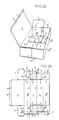
- a bottom wall is seen to be composed of two bottom sections C which are mutually hingeable along a folding line 1, whilst the bottom wall is hingingly connected to two side walls A along at least a part of its longitudinal edges, denoted folding lines 2.
- the packing device according to figures 1a-1b can be brought from a substantially flat position, in which inner sides of the bottom sections C face each other, into an upright position (figure 1a) in which the side walls A are substantially perpendicular to the bottom wall and are attached to one another with the aid of a fixing flap D. It is to be observed that the fold 1 on which the bottom sections C are mutually hingeable runs parallel to the folds 2 on which the side walls A and the bottom wall are mutually hingeable.
- the side walls A are each divided by means of folding lines 3 into sections A I , A II and A III , so that in the upright position of the packing device (figure 1a) sections A I and A III constitute the end side walls of the packing device and sections A II form the side walls of the packing device in the longitudinal direction.
- the side wall sections A I are each connected hingingly at least along a part of their longitudinal edges, denoted folding lines 4, to side wings E which in the upright position of the packing device (figure 1a) are disposed parallel to the bottom sections C.
- the side wings E are each provided with two side segments E I and E II which are mutually hingeable along folding lines 5 and which are separated from one another along intersection lines 6. Adjacent side wings E are separated from one another by means of an intersection line 7.
- the side segments E I and E II lie substantially in one plane in the flat and upright positions of the packing device, in which positions adjacent side wings E are attached to one another with the aid of a fixing flap K.
- One side wall A II is hingeably connected along at least a part of its longitudinal edges to a cover wall G which in the upright position of the packing device (figure 1a) can be folded in.
- the cover wall G is hingeably connected along the longitudinal edges 8 to cover wall wings H I , H II , H III .
- the cover wall G is provided with a folding line 9 and an intersecting line 10 to function as a display wall.
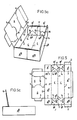
- the packing device according to figures 2a-2b corresponds with that according to figures 1a-1b, it being understood that two side wall sections A I are hingingly connected to strengthening flaps L along at least a part of their longitudinal edges, denoted folding lines 11. These strengthening flaps L can be brought parallel to the side wall sections A I (along the arrrow of figure 2a) thus strengthening these side wall sections A I .
- Parts of the packing device according to figures 2a-2b which correspond with parts of the packing device according to figures 1a-1b have been denoted with the same reference numerals.
- the packing device according to figures 3a-3b corresponds with that according to figures 1a-1b, on the understanding that the cover wall G is separated from the respective side wall section A II along the intersecting line 12, and is hingingly connected therewith along the folding line 13, thus allowing the cover wall G to function as a display wall (figure 3a).
- a side wall section A II is hingeably connected with a supporting flap M which supports the cover wall when used as a display wall (figure 3a).
- Parts of the packing device according to figures 3a-3b which correspond with parts of the packing device according to figures 1a-1b have been denoted with the same reference numerals.
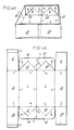
- a bottom wall is seen to be composed of two bottom sections C which are mutually hingeable along a folding line 1, whilst the bottom wall is hingingly connected to two side walls A along at least a part of its longitudinal edges, denoted folding lines 2.
- the packing device according to figures 4a-4b can be brought from a substantially flat position, in which inner sides of the bottom sections C face each other, into an upright position (figure 4a) in which the side walls A are substantially perpendicular to the bottom wall and are attached to one another with the aid of a fixing flap D.
- the fold 1 on which the bottom sections C are mutually hingeable runs parallel to the folds 2 on which the side walls A and the bottom wall are mutually hingeable.
- the side walls A are again each divided by means of folding lines 3 into sections A I , A II and A III , so that in the upright position of the packing device (figure 4a) sections A I and A III constitute the end side walls of the packing device and sections A II form the side walls of the packing device in the longitudinal direction.
- the bottom sections C are each connected hingingly at least along a part of their longitudinal edges, denoted folding lines 14, to bottom wings B which in the upright position of the packing device (figure 4a) are at right angles to the bottom sections C.
- the bottom wings B are each provided with two bottom segments B I and B II which are mutually hingeable along folding lines 15 and which are separated from one another along intersecting lines 16.
- the bottom segments B I and B II lie substantially in one plane in the flat and upright positions of the packing device.
- Adjacent bottom wings B are mutually hingeable along folding lines 17.
- FIG. 5a-5c corresponds with that according to figures 4a-4b, it being understood that one side wall A II is provided with a supporting flap M and the other side wall A II is provided with a cover wall G, in accordance with the packing device according to figures 3a-3b.
- Figure 5c shows a side view of the packing device of figure 5a, wherin the cover wall G has been turned into a display wall.
- Parts of the packing device according to figures 4-5 which correspond with parts of the packing device according to figures 1-3 have been denoted with the same reference numerals.
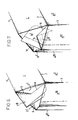
- Figures 6 and 7 show the way in which a packing device according to figures 1-3 and figures 4-5 can be brought from a substantially flat position into an upright position (and vice versa), respectively, by putting the side wings E and bottom wings B inwardly (and outwardly), respectively.
- folding lines and intersection lines are shown as discontinues and continues lines, respectively.
Landscapes
- Engineering & Computer Science (AREA)
- Mechanical Engineering (AREA)
- Cartons (AREA)
Applications Claiming Priority (2)
| Application Number | Priority Date | Filing Date | Title |
|---|---|---|---|
| NL8902551 | 1989-10-16 | ||
| NL8902551A NL8902551A (nl) | 1989-10-16 | 1989-10-16 | Uit een plano vervaardigde verpakking. |
Publications (2)
| Publication Number | Publication Date |
|---|---|
| EP0423892A2 true EP0423892A2 (fr) | 1991-04-24 |
| EP0423892A3 EP0423892A3 (en) | 1992-04-08 |
Family
ID=19855457
Family Applications (1)
| Application Number | Title | Priority Date | Filing Date |
|---|---|---|---|
| EP19900202733 Withdrawn EP0423892A3 (en) | 1989-10-16 | 1990-10-15 | Packing device made from one unitary blank |
Country Status (2)
| Country | Link |
|---|---|
| EP (1) | EP0423892A3 (fr) |
| NL (1) | NL8902551A (fr) |
Cited By (5)
| Publication number | Priority date | Publication date | Assignee | Title |
|---|---|---|---|---|
| US5735423A (en) * | 1995-07-28 | 1998-04-07 | William S. Black | Foldable self-standing container with method of manufacture and bulk dispenser |
| GB2339191A (en) * | 1998-07-08 | 2000-01-19 | David John Lee | Packaging device |
| US6112928A (en) * | 1995-07-28 | 2000-09-05 | Box Ease International | Foldable self-standing container with method of manufacture and bulk dispenser |
| GB2349871A (en) * | 1999-05-11 | 2000-11-15 | Hugh Martin | Packing system |
| GB2497720A (en) * | 2011-08-15 | 2013-06-26 | Global Trading Uk Ltd | Display carton |
Family Cites Families (4)
| Publication number | Priority date | Publication date | Assignee | Title |
|---|---|---|---|---|
| US2331582A (en) * | 1941-05-21 | 1943-10-12 | Fleishhacker Paper Box Company | Collapsible container |
| US2430755A (en) * | 1944-05-24 | 1947-11-11 | Robert Morris Bergstein | Method of making collapsed boxes |
| US3369729A (en) * | 1965-12-27 | 1968-02-20 | Sage Folding Box Co | Collapsible container |
| US4750612A (en) * | 1987-07-13 | 1988-06-14 | Manville Corporation | Combination shipping and display carton |
-
1989
- 1989-10-16 NL NL8902551A patent/NL8902551A/nl not_active Application Discontinuation
-
1990
- 1990-10-15 EP EP19900202733 patent/EP0423892A3/en not_active Withdrawn
Cited By (5)
| Publication number | Priority date | Publication date | Assignee | Title |
|---|---|---|---|---|
| US5735423A (en) * | 1995-07-28 | 1998-04-07 | William S. Black | Foldable self-standing container with method of manufacture and bulk dispenser |
| US6112928A (en) * | 1995-07-28 | 2000-09-05 | Box Ease International | Foldable self-standing container with method of manufacture and bulk dispenser |
| GB2339191A (en) * | 1998-07-08 | 2000-01-19 | David John Lee | Packaging device |
| GB2349871A (en) * | 1999-05-11 | 2000-11-15 | Hugh Martin | Packing system |
| GB2497720A (en) * | 2011-08-15 | 2013-06-26 | Global Trading Uk Ltd | Display carton |
Also Published As
| Publication number | Publication date |
|---|---|
| NL8902551A (nl) | 1991-05-16 |
| EP0423892A3 (en) | 1992-04-08 |
Similar Documents
| Publication | Publication Date | Title |
|---|---|---|
| US3397771A (en) | Container | |
| US2741416A (en) | Container | |
| US4053101A (en) | Combination shipping container and display box | |
| US2116513A (en) | Collapsible carton | |
| US2891711A (en) | Package and bird feeder | |
| ES2064357T3 (es) | Caja de carton de carga por los extremos y metodo para cargarla. | |
| US4166568A (en) | Polygonal container | |
| US3653576A (en) | Folding container having triangular cross section | |
| US4202485A (en) | Container and blank therefor | |
| GB1527189A (en) | Folding box for holding and displaying articles such as fruit and vegetables | |
| US3905543A (en) | Hollow walled carton structure | |
| EP0423892A2 (fr) | Dispositif d'emballage formé à partir d'un flanc unique | |
| US3302845A (en) | Paperboard packet and blank therefor | |
| US3253769A (en) | Collapsible carton | |
| US3819035A (en) | Frame carton | |
| US2758778A (en) | Window display carton | |
| US2898029A (en) | Handled carton | |
| US3420362A (en) | Display carton for tubes or bottles | |
| MA22964A1 (fr) | Caisse en carton . | |
| US3232518A (en) | Hinged cover carton | |
| US1798612A (en) | Two-piece carton satchel | |
| US4279375A (en) | Shipping-display container | |
| US1751782A (en) | Carton for sectoral canopies | |
| US3092302A (en) | Storage container | |
| GB1502431A (en) | Container |
Legal Events
| Date | Code | Title | Description |
|---|---|---|---|
| PUAI | Public reference made under article 153(3) epc to a published international application that has entered the european phase |
Free format text: ORIGINAL CODE: 0009012 |
|
| AK | Designated contracting states |
Kind code of ref document: A2 Designated state(s): BE CH DE DK ES FR GB IT LI NL SE |
|
| PUAL | Search report despatched |
Free format text: ORIGINAL CODE: 0009013 |
|
| AK | Designated contracting states |
Kind code of ref document: A3 Designated state(s): BE CH DE DK ES FR GB IT LI NL SE |
|
| STAA | Information on the status of an ep patent application or granted ep patent |
Free format text: STATUS: THE APPLICATION IS DEEMED TO BE WITHDRAWN |
|
| 18D | Application deemed to be withdrawn |
Effective date: 19921009 |