EP0424065A2 - Vorrichtungen zum Prägen von skulptierten Mustern - Google Patents
Vorrichtungen zum Prägen von skulptierten Mustern Download PDFInfo
- Publication number
- EP0424065A2 EP0424065A2 EP90311256A EP90311256A EP0424065A2 EP 0424065 A2 EP0424065 A2 EP 0424065A2 EP 90311256 A EP90311256 A EP 90311256A EP 90311256 A EP90311256 A EP 90311256A EP 0424065 A2 EP0424065 A2 EP 0424065A2
- Authority
- EP
- European Patent Office
- Prior art keywords
- roller
- design
- water
- housing
- permit
- Prior art date
- Legal status (The legal status is an assumption and is not a legal conclusion. Google has not performed a legal analysis and makes no representation as to the accuracy of the status listed.)
- Withdrawn
Links
Images


Classifications
-
- B—PERFORMING OPERATIONS; TRANSPORTING
- B44—DECORATIVE ARTS
- B44B—MACHINES, APPARATUS OR TOOLS FOR ARTISTIC WORK, e.g. FOR SCULPTURING, GUILLOCHING, CARVING, BRANDING, INLAYING
- B44B5/00—Machines or apparatus for embossing decorations or marks, e.g. embossing coins
- B44B5/02—Dies; Accessories
- B44B5/026—Dies
-
- B—PERFORMING OPERATIONS; TRANSPORTING
- B28—WORKING CEMENT, CLAY, OR STONE
- B28B—SHAPING CLAY OR OTHER CERAMIC COMPOSITIONS; SHAPING SLAG; SHAPING MIXTURES CONTAINING CEMENTITIOUS MATERIAL, e.g. PLASTER
- B28B11/00—Apparatus or processes for treating or working the shaped or preshaped articles
- B28B11/08—Apparatus or processes for treating or working the shaped or preshaped articles for reshaping the surface, e.g. smoothing, roughening, corrugating, making screw-threads
- B28B11/0818—Apparatus or processes for treating or working the shaped or preshaped articles for reshaping the surface, e.g. smoothing, roughening, corrugating, making screw-threads for roughening, profiling, corrugating
-
- B—PERFORMING OPERATIONS; TRANSPORTING
- B28—WORKING CEMENT, CLAY, OR STONE
- B28B—SHAPING CLAY OR OTHER CERAMIC COMPOSITIONS; SHAPING SLAG; SHAPING MIXTURES CONTAINING CEMENTITIOUS MATERIAL, e.g. PLASTER
- B28B3/00—Producing shaped articles from the material by using presses; Presses specially adapted therefor
- B28B3/12—Producing shaped articles from the material by using presses; Presses specially adapted therefor wherein one or more rollers exert pressure on the material
-
- B—PERFORMING OPERATIONS; TRANSPORTING
- B44—DECORATIVE ARTS
- B44B—MACHINES, APPARATUS OR TOOLS FOR ARTISTIC WORK, e.g. FOR SCULPTURING, GUILLOCHING, CARVING, BRANDING, INLAYING
- B44B5/00—Machines or apparatus for embossing decorations or marks, e.g. embossing coins
- B44B5/0004—Machines or apparatus for embossing decorations or marks, e.g. embossing coins characterised by the movement of the embossing tool(s), or the movement of the work, during the embossing operation
- B44B5/0009—Rotating embossing tools
-
- E—FIXED CONSTRUCTIONS
- E04—BUILDING
- E04F—FINISHING WORK ON BUILDINGS, e.g. STAIRS, FLOORS
- E04F21/00—Implements for finishing work on buildings
-
- E—FIXED CONSTRUCTIONS
- E04—BUILDING
- E04F—FINISHING WORK ON BUILDINGS, e.g. STAIRS, FLOORS
- E04F21/00—Implements for finishing work on buildings
- E04F21/02—Implements for finishing work on buildings for applying plasticised masses to surfaces, e.g. plastering walls
- E04F21/16—Implements for after-treatment of plaster or the like before it has hardened or dried, e.g. smoothing-tools, profile trowels
Definitions
- This invention is a hand held apparatus which uses embossed design rollers to sculpture those designs in preapplied dry wall compound or other suitable material on ceilings or walls. It is self cleaning in that the design rollers are continuously cleaned with jets of water over the length of the roller. The water is drawn off by vacuum, e.g. by a standard shop type vacuum.
- Wall printing developed in Germany in the 1940s, is the business from which the idea for a machine to sculpture permanent designs on ceilings and walls was conceived.
- Wallprinting is the process of using an applicator which applies the proper amount of latex paint to the applicator's embossed design roller to simulate wallpaper as it is rolled vertically down the wall.
- embossed design rollers used for sculpturing are purchased from German and Italian wall printing equipment manufacturers. In none of their catalogs has an advertisement for any type of sculpturing equipment been seen.
- the object of the invention is development of a self cleaning, hand held machine capable of sculpturing walls and ceilings, or any specific area of wall or ceiling, with any design of choice.
- the invention provides a device for imprinting an embossed design, which comprises an imprinting roller having a design formed as projections on its surface, mounted rotatably in a housing with part of the roller exposed so that it can be rolled along the surface to be imprinted.
- the housing is formed as a liquid-type container, and is provided with means for spraying the roller in the housing with jets of water, in order to clean the roller in operation.
- the housing prevents any substantial escape of the water jets to the exterior past the roller. It may be provided with one or more handles, generally projecting away in a direction opposing the direction in which the exposed roller surface faces, to be held by a user in operation.
- a barrier or baffle is provided inside the housing between the or each vacuum out-take and the water jets, to limit interference with the latter by the former.
- An advantage of this invention is that it is innovative and time saving. At present any sculpturing on walls or ceilings is done only by hand by skilled artists.
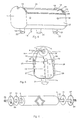
- Figure 1 shows the roller core 9 without the design cover. It is made of plastic or other suitable stable waterproof material.
- the large flange 8 at each end of the roller fits into a depression in the foam rubber collar 13 Fig 3, 4. Collar 13, has a thickness equal to the length of flange 8 Fig. 1.
- the collar is securly glued to the upper portion of the inner side of each housing side 11 Fig 3, 4, 8.
- the purpose of collar 13 is to contain the water used to clean the design cover 6 Fig. 2 which fits over core 9.
- the lower part of foam rubber collar 13 touches the upper end of housing front 27 Fig 4 and housing back 28 Fig 5.
- the axle 7 at each end of the roller core 9 snaps into notch 12 of Fig 3, 4. This permits switching from one design roller to another in a matter of seconds.
- flange 8 or axle 7 as being left or right in Fig 1 as both sides of core 9 are identical.
- the part on the left side is identical to the part on the right side and has an identical number.
- Figure 2 shows the flexible standard wall printing roller design cover 6.
- the circular spacer 10 Fig 2 is placed over each flange 8 fig 1.
- the purpose of said spacer is to prevent friction between the turning roller design cover 6 and the foam rubber collar 13 Fig 3, 4.
- roller design cover 6, now installed over core 9, will together be referenced as design roller 6A (assembly) meaning the roller core 9, including both flanges 8 and both axles 7, and design cover 6 combination.
- FIG 3 shows an angle view of the housing with housing front 27 Fig. 4, 5, and front water deflector 24 Fig. 4, 5, removed.
- Sides 11 of flexible plastic show the notch 12 that the roller axle 7 Fig 1 snaps into.
- the notch is so designed that as the design roller 6A is being moved across wall or ceiling, the heavy portion of the notch material in side 11 is holding the roller in. It cannot fall out in usage.
- the assembly 14 is made of copper tubing or other suitable material and positioned so that the water jet holes on top are sufficiently below the bottom of the inserted design roller and angled so that the water jets lift all particles of sculpture material (usually dry wall joint compound) from the moving design roller.
- Handle 31 Fig 7, 8 permanently fastened to the exterior of each side 11 seals hole 30 Fig 5 against wager leakage and any side movement of T shaped water spray assembly 14.
- the vertical leg of T shaped water assembly 14 protrudes through the housing bottom 16 Fig 5.
- Adjustable water pressure in said T assembly 14 is provided by a water hose and valve (not shown) attached to the lower end of the T assembly.
- Center barrier 15 Fig 3, 5, 8, keeps the water jets on the cleansing side of the housing assembly from being affected by the vacuum action on the other side of barrier 15.
- Said barrier 15 is fastened vertically to the center of each housing side 11 Fig 3, 8, and to the center of housing bottom 16 Fig 5.
- Barrier 15 has two quarter circle cutouts 17 Fig 3, 5, having 20 millimeter radius.
- One quarter circle cutout is centered at the joining point of barrier 15 with each housing side 11 and housing bottom 16.
- Said barrier 15 also has three half circle cutouts 32 Fig 3 of 15 millimeter radius located at its connection with bottom 16 Fig 5.
- One cutout is in the center of the barrier 15 length, and the other two are spaced midway between the center cutout and the end cutouts 17 Fig 3, 5.
- Barrier extension 18 Fig 3, 8 is a thin plastic shield whose length is equal to the combined length of design cover 6 Fig 2 and the two circular spacers 10 Fig 2. Barrier extension 18 is fastened to the upper portion of barrier 15 so that its top edge is approximately 4 millimeters below the inserted design roller 6A. Being an upward extension of the barrier 15, it serves the same purpose, to prevent the vacuum action from affecting the cleaning action of the water jets. Barrier extension 18 is fastened to barrier 15 with four brass round head screws 23 Fig 3, 8 and is adjustable vertically with slotted screw holes.
- FIG. 8 The left side of figure 8, a cutaway top view, reveals the relationship between the inserted design roller assembly 6A, circular spacer 10, flange 8, axle 7, side 11, foam collar 13, front water deflector 24, and back water deflector 29.
- Vacuum spout 20 Fig 3 is normally used when applying sculptured designs on ceilings and vertical designs on walls. At these times vacuum spouts 19 and 21 Fig 3, 4 are each capped with snug fitting cap 22 Fig 3, 4. When sculpturing a wall design horizontally from left to right, the vacuum hose is attached to vacuum spout 21 Fig 3, 4, and spouts 19 and 20 are each capped using cap 22. When sculpturing a wall design horizontally from right to left, the vacuum nose is attached to vacuum spout 19 and spouts 20 and 21 are each capped. These changes of the vacuum hose are necessary to eliminate the possibility of water leakage in horizontal sculpturing as the water naturally falls to the lower housing side 11 and the vacuum hose must be placed at that lower position.
- FIG 4 is a front view of the self cleaning sculpturing machine with the design roller 6A removed.
- Front water deflector 24 Fig 4 is a piece of 2 millimeter flexible plastic with a length equal to the combined length of design cover 6 Fig 2 and the two circular spacers 10 Fig 2. Its width, top to bottom, is 75 mm. and its purpose is to keep the cleansing water within the machine. Its top edge is 4 millmeters above the center line of the installed design roller 6A. This provides maximum design roller 6A exposure.
- Front water deflector 24 is pivoted into contact with the design roller 6A through use of front foam rubber pivot strip 26 Fig 4, 5, 8. Said pivot strip is 15 millimeters square and extends from the left side to the right side of the housing.
- Front water deflector 24 pivots on pivot strip 26 through adjustment of two self taping adjusting screws 25 Fig 4. These screws, 25 mm. long, are placed through holes in housing front 27. These holes are located 30 mm. below the top edge of housing front 27 and 50 mm. from either housing side 11.
- the self taping screws 25 making intrusion into the lower part of front water deflector 24, are used to adjust the pivotal action of deflector 24 so that the top edge of the deflector contacts design roller 6A just above the roller's midpoint.
- Figure 5 a visual drawing of the right side view of the housing assembly, shows the relationship of right housing side 11, design roller cover 6 (over core 9), flange 8, axle 7, T shaped water jet spray assembly 14, hole 30, center barrier 15, barrier extension 18, housing bottom 16, vacuum spout 21, front 27, back 28, front water deflector 24, back water deflector 29, front and back pivot strips 26, and front and back adjusting screws 25.
- housing back 28 is identical to housing front 27
- back water deflector 29 is identical to front water deflector 24
- front and back pivot strips 26 are identical
- front and back adjusting screws 25 are identical.
- the curved arrow above design cover 6 indicates the direction in which the design roller always turns.
- the design roller After putting the sculptured impression into the dry wall compound, cement, clay, mortar or other material, the design roller enters the cleansing water jet spray enclosure area formed by back extension 29, housing back 28, the back half of bottom 16, the back half of both housing sides 11, center barrier 15, and barrier extension 18.
- the design roller is thoroughly cleaned of adhering material and, as it passes barrier extension 18, it enters the vacuum enclosure where it is vacuum cleaned of all water and material particles.
- the vacuum enclosure is formed by housing front 27, front water deflector 24, the front half of housing bottom 16, the front half of both housing sides 11, center barrier 15, and barrier extension 18.
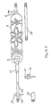
- Figure 6 depicts the mechanism for sculpturing designs that do not circumvent the design roll and therefore will not roll freely.
- the design shown in figure 6 is such a design. It requires a rubber tired wheel 37 to be attached to each axle 36. This is accomplished by use of wheel axle clamp 38 which is a physical part of the rubber tired wheel.
- This mechanism uses core 33 (not shown) which is covered by a design cover 6.
- Core 33 is identical in size to core 9 Fig 1.
- Its flanges 8 are identical to those of core 9, but has axles 36 which are the the same diameter as those of axle 7 Fig 1 but are considerably longer and are threaded on each end.
- a circular spacer 10 is slid over each flange 8 and the assembly, with axles 36, is snapped into notch 12 Fig 3, 4 of each housing side.
- a rubber tired wheel 37 is then clamped onto each axle 36 where it extends beyond the housing side 11.
- the wheels permit a design such as that shown in figure 6 to be sculptured in ceiling borders, etc.
- the wheels are positioned on the axle in such manner that they do not track through the area prepared for sculpturing. This mechanism, designed for borders is not applicable to sculpturing of wide areas.
- Figure 6A is a mechanism used for sculpturing circles when snapped into the machine.
- Design cover 6 over core 33, with flanges 8, circular spacers 10, and axles 36 is snapped into the machine. With the design shown, the rubber tired wheels are not used.
- couplings 42 and axle extensions 35 one axle is extended to a length greater than the radius of the circle.
- Circle clamping pivot 40 is fastened to the axle extension to provide the proper radius for the sculptured design.
- Clamping pivot handle 41 which rotates freely on the clamping pivot, is held by a second party as the sculptured design is rolled into the prepared circular area.
- Figure 7 shows a complete device with right and left vertical handles 31 attached at the ends of the housing, extending in the opposite direction to that in which the exposed roller portion faces.
Landscapes
- Engineering & Computer Science (AREA)
- Architecture (AREA)
- Structural Engineering (AREA)
- Civil Engineering (AREA)
- Chemical & Material Sciences (AREA)
- Ceramic Engineering (AREA)
- Mechanical Engineering (AREA)
- Manufacturing & Machinery (AREA)
- Cleaning By Liquid Or Steam (AREA)
Applications Claiming Priority (2)
| Application Number | Priority Date | Filing Date | Title |
|---|---|---|---|
| US07/430,833 US5000671A (en) | 1989-10-20 | 1989-10-20 | Machine for imprinting sculptured designs on walls and ceilings |
| US430833 | 1989-10-20 |
Publications (2)
| Publication Number | Publication Date |
|---|---|
| EP0424065A2 true EP0424065A2 (de) | 1991-04-24 |
| EP0424065A3 EP0424065A3 (en) | 1991-09-11 |
Family
ID=23709246
Family Applications (1)
| Application Number | Title | Priority Date | Filing Date |
|---|---|---|---|
| EP19900311256 Withdrawn EP0424065A3 (en) | 1989-10-20 | 1990-10-15 | Devices for imprinting sculptured designs |
Country Status (2)
| Country | Link |
|---|---|
| US (1) | US5000671A (de) |
| EP (1) | EP0424065A3 (de) |
Families Citing this family (24)
| Publication number | Priority date | Publication date | Assignee | Title |
|---|---|---|---|---|
| US5448794A (en) * | 1993-09-16 | 1995-09-12 | Electrolux Corporation | Corded handheld vacuum cleaner |
| US5615444A (en) * | 1995-08-29 | 1997-04-01 | Reye; Barbara J. | Roller printer for walls and the like with leveling feature |
| US5577291A (en) * | 1996-01-02 | 1996-11-26 | Myers; Micheal J. | Decorative paint roller device |
| US5980802A (en) * | 1997-04-11 | 1999-11-09 | Wagner Spray Tech Corporation | Method for treating paint roller covers |
| US6390801B1 (en) | 1998-01-06 | 2002-05-21 | Steven Dale Smith | Texturing tool |
| US6203309B1 (en) | 1998-08-10 | 2001-03-20 | Wagner Spray Tech Corporation | Apparatus for embossing paint rollers |
| US6305045B1 (en) | 1999-07-08 | 2001-10-23 | Newell Operating Company | Paint supply and finishing system |
| GB2356376B (en) * | 2000-06-30 | 2001-10-10 | Andrew Stewart Roberts | Apparatus for applying a finish to a texturable decorative coating |
| USD463135S1 (en) | 2000-10-19 | 2002-09-24 | Susan Goans Driggers | Roller cover |
| US6680083B2 (en) | 2001-04-18 | 2004-01-20 | Robert M. Ray | Ceiling design tool and method |
| CN2657795Y (zh) * | 2003-11-03 | 2004-11-24 | 卢伟明 | 可调滚刷架 |
| US20050093204A1 (en) * | 2003-11-05 | 2005-05-05 | Gregg David W. | Stamping apparatus |
| US7306442B2 (en) * | 2005-10-31 | 2007-12-11 | Fox Shirl G | Pneumatic mud stamp |
| US20080067717A1 (en) * | 2006-09-15 | 2008-03-20 | Michael Lampignano | Apparatus for creating textured concrete surfaces |
| US20100251664A1 (en) * | 2009-04-06 | 2010-10-07 | Antonio Pinto | Wall design imprint tool |
| US9744394B2 (en) * | 2011-04-13 | 2017-08-29 | Kenneth D. Frederick | Exercising device with multi-position handle and method therefore |
| US9808665B1 (en) * | 2016-06-25 | 2017-11-07 | Eternal Evolution LLC | Exercise device |
| US10004942B1 (en) * | 2017-02-13 | 2018-06-26 | Jss Sports Co., Ltd. | Wheel exercising device |
| US10046198B1 (en) * | 2017-02-13 | 2018-08-14 | Jss Sports Co., Ltd. | Wheel exercising device |
| US20190045800A1 (en) * | 2017-08-09 | 2019-02-14 | Sharon Knudsen | Sleeve for making patterns |
| US20190105533A1 (en) * | 2017-10-05 | 2019-04-11 | Inventive Clinical Solutions | Shoulder Rehabilitation Tool |
| US12127991B2 (en) * | 2018-05-04 | 2024-10-29 | Zackary Daley | Exercise device having telescoping elements |
| CN109304977A (zh) * | 2018-10-25 | 2019-02-05 | 东莞润如智能科技有限公司 | 一种具有灰尘降解功能的可远程监控的智能雕刻设备 |
| CN111101691A (zh) * | 2019-12-30 | 2020-05-05 | 成都富思特新材料有限公司 | 一种用于艺术涂料的滚筒制作方法 |
Family Cites Families (11)
| Publication number | Priority date | Publication date | Assignee | Title |
|---|---|---|---|---|
| GB588477A (en) * | 1945-02-21 | 1947-05-22 | Orlit Ltd | A new or improved machine for applying surface finish to concrete and like slabs |
| US2485428A (en) * | 1947-08-07 | 1949-10-18 | Altman | Self-feeding paint roller device |
| FR1022166A (fr) * | 1950-07-19 | 1953-03-02 | Appareil portatif combiné pour décoration murale et applications similaires | |
| US3748678A (en) * | 1971-12-30 | 1973-07-31 | Knight Oil Corp | Rotary brush |
| US4201801A (en) * | 1976-05-12 | 1980-05-06 | Nippon Paint Co., Ltd. | Method of forming a decorative relief pattern |
| US4257140A (en) * | 1978-04-28 | 1981-03-24 | Imperial Chemical Industries Limited | Painting device |
| DE3239761A1 (de) * | 1982-09-17 | 1984-05-03 | Ewald 5620 Velbert Syring | Schablone und verfahren zum aufbringen eines reliefverputzes auf eine wandflaeche |
| US4667363A (en) * | 1985-05-03 | 1987-05-26 | Thomas Industries, Inc. | Roller paint guard assembly |
| US4735567A (en) * | 1986-08-04 | 1988-04-05 | Frakes Raymond J | Apparatus for applying a predetermined surface effect |
| US4897121A (en) * | 1987-10-05 | 1990-01-30 | Torao Sasaki | Removal process of asbestos-filled linings or coatings |
| US4765353A (en) * | 1987-11-06 | 1988-08-23 | Rhoades Clark J | Paint roller shield with integral washing spray guard |
-
1989
- 1989-10-20 US US07/430,833 patent/US5000671A/en not_active Expired - Fee Related
-
1990
- 1990-10-15 EP EP19900311256 patent/EP0424065A3/en not_active Withdrawn
Also Published As
| Publication number | Publication date |
|---|---|
| EP0424065A3 (en) | 1991-09-11 |
| US5000671A (en) | 1991-03-19 |
Similar Documents
| Publication | Publication Date | Title |
|---|---|---|
| EP0424065A2 (de) | Vorrichtungen zum Prägen von skulptierten Mustern | |
| PT74396A (en) | Child-resistant liquid dispenser sprayer or like apparatus | |
| WO2001083216A3 (en) | Method and apparatus for automatically cleaning both the blanket cylinder and the ink rollers of a printing press | |
| DE3066305D1 (en) | Method and apparatus for rinsing, cleaning, disinfecting and coating a conduit on the interior, especially a water conduit in a new construction | |
| GB9018280D0 (en) | Paint roller cleaning apparatus | |
| DE4009044A1 (de) | Malerwalze | |
| EP0990521A3 (de) | Vorrichtung und Verfahren zum Reinigen von Teilen von Druckmaschinen | |
| ATE38490T1 (de) | Vorrichtung zum befeuchten der druckplatte an rotationsdruckmaschinen. | |
| GB9221739D0 (en) | Device for the zonewise metering of a fluid medium on a roller in a printing machine | |
| DE69622243D1 (de) | Drehantriebsvorrichtung zum Drehen der Rolle eines Rolladens | |
| GB2123066A (en) | Marking device | |
| EP0135978A3 (de) | Dekontaminationseinrichtung | |
| GB9415444D0 (en) | Paint roller cleaning apparatus | |
| JPH03116313U (de) | ||
| GB2287178B (en) | Paint roller cleaning and drying apparatus | |
| PL319675A1 (en) | Device for cleaning paint application rollers | |
| JPH0225626Y2 (de) | ||
| FR2707852B1 (fr) | Dispositif pour le nettoyage d'un rouleau de peinture. | |
| GB9824679D0 (en) | Paint roller cleaning apparatus | |
| JPS6227257Y2 (de) | ||
| CN85205117U (zh) | 滚筒涂刷器 | |
| JPH0425797Y2 (de) | ||
| JPS61168837A (ja) | カラ−ブラウン管用内面縁拭い装置 | |
| JPH0474991U (de) | ||
| JP2576690Y2 (ja) | 硬基板塗布装置 |
Legal Events
| Date | Code | Title | Description |
|---|---|---|---|
| PUAI | Public reference made under article 153(3) epc to a published international application that has entered the european phase |
Free format text: ORIGINAL CODE: 0009012 |
|
| AK | Designated contracting states |
Kind code of ref document: A2 Designated state(s): DE ES FR GB IT |
|
| PUAL | Search report despatched |
Free format text: ORIGINAL CODE: 0009013 |
|
| AK | Designated contracting states |
Kind code of ref document: A3 Designated state(s): DE ES FR GB IT |
|
| STAA | Information on the status of an ep patent application or granted ep patent |
Free format text: STATUS: THE APPLICATION IS DEEMED TO BE WITHDRAWN |
|
| 18D | Application deemed to be withdrawn |
Effective date: 19920312 |