EP0424101A1 - Appareil de commande de robinet d'eau - Google Patents
Appareil de commande de robinet d'eau Download PDFInfo
- Publication number
- EP0424101A1 EP0424101A1 EP90311334A EP90311334A EP0424101A1 EP 0424101 A1 EP0424101 A1 EP 0424101A1 EP 90311334 A EP90311334 A EP 90311334A EP 90311334 A EP90311334 A EP 90311334A EP 0424101 A1 EP0424101 A1 EP 0424101A1
- Authority
- EP
- European Patent Office
- Prior art keywords
- spring
- faucet
- housing
- valve
- retainer
- Prior art date
- Legal status (The legal status is an assumption and is not a legal conclusion. Google has not performed a legal analysis and makes no representation as to the accuracy of the status listed.)
- Ceased
Links
- XLYOFNOQVPJJNP-UHFFFAOYSA-N water Substances O XLYOFNOQVPJJNP-UHFFFAOYSA-N 0.000 claims abstract description 41
- 230000006835 compression Effects 0.000 claims abstract description 16
- 238000007906 compression Methods 0.000 claims abstract description 16
- 239000012530 fluid Substances 0.000 claims description 6
- 230000037431 insertion Effects 0.000 claims 1
- 238000003780 insertion Methods 0.000 claims 1
- 108010036050 human cationic antimicrobial protein 57 Proteins 0.000 description 7
- 238000010276 construction Methods 0.000 description 3
- 239000000853 adhesive Substances 0.000 description 1
- 230000001070 adhesive effect Effects 0.000 description 1
- 230000001419 dependent effect Effects 0.000 description 1
- 230000000881 depressing effect Effects 0.000 description 1
- 230000000994 depressogenic effect Effects 0.000 description 1
- 230000001939 inductive effect Effects 0.000 description 1
- 210000002445 nipple Anatomy 0.000 description 1
- 230000000284 resting effect Effects 0.000 description 1
- 230000000717 retained effect Effects 0.000 description 1
- 238000009420 retrofitting Methods 0.000 description 1
Images

Classifications
-
- F—MECHANICAL ENGINEERING; LIGHTING; HEATING; WEAPONS; BLASTING
- F16—ENGINEERING ELEMENTS AND UNITS; GENERAL MEASURES FOR PRODUCING AND MAINTAINING EFFECTIVE FUNCTIONING OF MACHINES OR INSTALLATIONS; THERMAL INSULATION IN GENERAL
- F16K—VALVES; TAPS; COCKS; ACTUATING-FLOATS; DEVICES FOR VENTING OR AERATING
- F16K47/00—Means in valves for absorbing fluid energy
-
- F—MECHANICAL ENGINEERING; LIGHTING; HEATING; WEAPONS; BLASTING
- F16—ENGINEERING ELEMENTS AND UNITS; GENERAL MEASURES FOR PRODUCING AND MAINTAINING EFFECTIVE FUNCTIONING OF MACHINES OR INSTALLATIONS; THERMAL INSULATION IN GENERAL
- F16K—VALVES; TAPS; COCKS; ACTUATING-FLOATS; DEVICES FOR VENTING OR AERATING
- F16K11/00—Multiple-way valves, e.g. mixing valves; Pipe fittings incorporating such valves
- F16K11/02—Multiple-way valves, e.g. mixing valves; Pipe fittings incorporating such valves with all movable sealing faces moving as one unit
- F16K11/06—Multiple-way valves, e.g. mixing valves; Pipe fittings incorporating such valves with all movable sealing faces moving as one unit comprising only sliding valves, i.e. sliding closure elements
- F16K11/078—Multiple-way valves, e.g. mixing valves; Pipe fittings incorporating such valves with all movable sealing faces moving as one unit comprising only sliding valves, i.e. sliding closure elements with pivoted and linearly movable closure members
-
- Y—GENERAL TAGGING OF NEW TECHNOLOGICAL DEVELOPMENTS; GENERAL TAGGING OF CROSS-SECTIONAL TECHNOLOGIES SPANNING OVER SEVERAL SECTIONS OF THE IPC; TECHNICAL SUBJECTS COVERED BY FORMER USPC CROSS-REFERENCE ART COLLECTIONS [XRACs] AND DIGESTS
- Y10—TECHNICAL SUBJECTS COVERED BY FORMER USPC
- Y10T—TECHNICAL SUBJECTS COVERED BY FORMER US CLASSIFICATION
- Y10T137/00—Fluid handling
- Y10T137/8593—Systems
- Y10T137/86493—Multi-way valve unit
- Y10T137/86549—Selective reciprocation or rotation
-
- Y—GENERAL TAGGING OF NEW TECHNOLOGICAL DEVELOPMENTS; GENERAL TAGGING OF CROSS-SECTIONAL TECHNOLOGIES SPANNING OVER SEVERAL SECTIONS OF THE IPC; TECHNICAL SUBJECTS COVERED BY FORMER USPC CROSS-REFERENCE ART COLLECTIONS [XRACs] AND DIGESTS
- Y10—TECHNICAL SUBJECTS COVERED BY FORMER USPC
- Y10T—TECHNICAL SUBJECTS COVERED BY FORMER US CLASSIFICATION
- Y10T137/00—Fluid handling
- Y10T137/8593—Systems
- Y10T137/86493—Multi-way valve unit
- Y10T137/86815—Multiple inlet with single outlet
Definitions
- This invention relates to slow closing faucets, and more particularly to a slow closing faucet of the spool valve type. Faucets are otherwise known as taps or cocks.
- a slow closing faucet assembly comprises a faucet housing, having inlets for hot and cold water and a common outlet; a spool valve in the housing the spool valve being rotational for controlling the relative flow of hot and cold water to the common outlet when said valve is rotated; the valve being reciprocable in controlled amounts between fully closed and fully open positions; the slow close mechanism comprising a housing subassembly having means for attachment to a faucet; a spring in the housing subassembly for biasing the faucet valve toward closed position; a hydraulic damper in said housing subassembly operably associated with said spring for resisting the closing action of said spring and thereby slowing the movement of said valve toward closed position; a control lever extending into the housing subassembly and having means for shifting the valve toward open position while shifting the spring against its biasing force and shifting the hydraulic damper; and adjustment means for the spring to enable the biasing force to be varied to thereby adjust the rate of movement of said valve toward the closed position.
- a faucet slow close mechanism comprises a housing subassembly having means for attachment to a faucet valve toward closed position; a hydraulic damper in said housing subassembly operably associated with said spring for resisting the biasing action of said spring and thereby slowing the movement of said valve toward closed position; a control lever extending into said housing subassembly and having means for shifting said valve toward the open position while shifting said spring against its biasing force; and adjustment means for said spring to enable said biasing force to be varied to thereby adjust the rate of movement of said valve toward the closed position.
- the slow close mechanism constructed according to the present invention are retrofitting to an existing single handle faucet with a spool-type valve, as well as to new faucets of such type. Its structure enables easy attachment followed by dependable operation at a desired preset closing rate. A particular closing rate can be easily reset by an authorised person, yet free from tampering by unauthorised persons. A single lever controls the water temperature and water flow rate at any of several preset valve closing rates. These flow variables can be achieved without interference with or by the other variables. The resulting product may be designed to be aesthetically appealing.
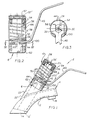
- the complete assembly 2 there depicted includes a spigot subassembly 4, a mixing valve subassembly 6, a valve actuator subassembly 8 and a slow close subsumable 10.
- Spigot subassembly 4 is of generally conventional construction, including an upwardly outwardly projecting faucet or spigot 12 having a base 14 for mounting it on a sink.
- Such spigot is hollow, including a water outlet 16 on the bottom of the upper outer end, and conventional hot and cold inlets at the base, leading to the hollow interior or conduit 12′ which forms a passageway.
- Projecting upwardly from the faucet and forming an integral part thereof is a hollow valve support or protrusion 22 having a flat annular outer surface 22′.
- the inner chamber 22 ⁇ of protrusion 22 is in alignment with and communicates directly with the lower portion of conduit 12′ in faucet 12.
- Mixing valve subassembly 6 is located within this chamber 22 ⁇ , extending down into the conduit 12′ and projecting at its upper end from chamber 22 ⁇ and beyond flat surface 22′ as indicated in Fig 1.
- This mixing valve subassembly is a spool valve type as set forth in US-A-4,495,969 or an equivalent spool valve.
- Subassembly 6 includes a valve stem 20 having a shaft portion 32 projecting upwardly from the main body of the valve, this shaft portion having a pair of flats 34 (Fig 3) on opposite sides thereof.
- Valve actuator subassembly 8 includes an actuator lever 40 capable of rotating valve stem 20 and of shifting it rectilinearly, as will be described more fully hereinafter.
- a pivot fulcrum offset or apex 42 Near the lower end of lever 40, is a pivot fulcrum offset or apex 42 which engages the upper surface of an annular fulcrum washer 44 just beneath the inner end of lever 40.
- the inner end of lever 40, as well as washer 44 and the upper protruding end of mixing valve subassembly 6 are all located within a cylindrical tubular housing or cover tube 58. This housing has internal threads at its lower end, threadably engaged onto a cylindrical mounting base 62.
- mounting base 62 abuts flat surface 22′ on the faucet projection, said base also surrounding the housing of mixing valve subassembly 6 (Fig 1).
- Mounting base 62 is secured against protrusion 22 by an annular retaining clip 64 which lies in the top of base 62 and has an inner annular surface which engages the housing of mixing valve subassembly 6. This annular clip bites into the periphery of the valve housing to secure the base and the members mounted thereabove to the faucet.
- Washer 44 rests on the outer annular end of valve subassembly 6, having a central opening to receive valve stem 20 therethrough. Resting on washer 44 is a lower guide adapter 52 which has a smaller diameter lower neck and a larger diameter upper head.
- lever 40 This head is secured between piston rods 90 and valve stem 20 to move rectilinearly therewith.
- the inner end of lever 40 is of forked construction, the bifurcated legs thereof protruding around the valve stem and engaging a pair of external flats on the neck of lower guide adapter or retainer 52 so that, when lever 40 is pivoted about the central axis of the valve stem, adapter 52 will also pivot therewith.
- This adapter has a central opening with internal flats matching those of outer flats 34 on valve stem 20 so that rotation of adapter 52 causes rotation of valve stem 20.
- the lower end of lever 40 is between underlying washer 44 and overlying guide adapter 52.
- This guide adapter also comprises a lower retainer for a compression coil spring 66 which has its lower end in engagement with retainer 52 and its upper end in engagement with upper adjustable retainer ring 54. Upper end in engagement with upper adjustable retainer ring 54.
- Upper retainer 54 is an annular member having threads on its outer peiphery in threaded engagement with corresponding threads on the inner surface of the upper end of tubular housing 58.
- At least two upwardly projecting cavities 54′ spaced from each other are located in retainer 54 for receipt of the prongs of a spanner wrench 80 (Figs 5 and 6). Clockwise or counterclockwise movement of retainer 54 by the spanner wrench thus applies greater or lesser compression on spring 66 to set the rate of valve closing.
- a tube cap 57 press fitted into the upper outer end of housing 58 and rotational therewith.
- This tube cap 57 is connected to hydraulic damper subassembly 56 by a nut (59) which engages the centre portion of the top surface of cap 57 and fits around and threadably engages the threaded nipple 82a protruding from the centre of hydraulic damper subassembly 56 and through cap 57.
- a dress cover 106 having spring legs 106′ is engageable with the arcuate openings 57′ in tube cape 57 to cover the mechanism.
- Hydraulic damper subassembly 56 comprises a tubular housing 82 containing an internal piston 84, a piston ring 86 and a washer 88, all retained on the inner end of the piston rod 90, the lower end of which extends through an opening 82′ in housing 82.
- the piston, ring and washer are rectilinearly movable within housing 82 along with rod 90.
- An hydraulic fluid in chamber 92 can move slowly past the position under compressive force of spring 66, from one side of the piston to the other within chamber 92.
- An annular seal 94 around the lower end of rod 90 prevents leakage of the fluid out of chamber 92.
- An annular guide 96 retains rod 90 in alignment.
- a passage 82 ⁇ having a ball type seal 98 therein, eg to allow filling.
- This passage 82 ⁇ is in protrusion 82a threaded on its exterior to receive nut 56′ (Fig 1).
- the lower extended end of rod 90 is also threaded to threadably engage within a threaded orifice in the upper end of spool valve stem 20.
- Operation of the slow close mechanism desirably enables the user to immediately select the output water temperature and flow rate with one lever, and at a valve closing rate determined only by authorised personnel and adjustable to suit the situation.
- Depressing lever 40 with a downward force allows the operator to dispense water from the faucet for the predetermined period of time. That is, when lever 40 is depressed, its canned pivot or fulcrum 42 on washer 44 provides the mechanical means necessary to lift lower guide adapter 52 and attached water faucet valve stem 20 to open position. Because both hydraulic damper subassembly 56 and compression spring 66 are attached to valve stem 20 and encapsulated by cover tube or housing 58, they are also lifted and compressed. Once compressed, the stored energy of compression spring 66 exerts force on the hydraulic damper subassembly, causing return to an extended or valve-closed state.
- the rate at which the water faucet valve closes depends upon the controlled metering of the hydraulic fluid contained in the hydraulic damper assembly and the spring rate of the compression spring.
- the speed for valve closure can be adjusted by inducing more or less compression force onto the spring. This adjustment is accomplished by removing dress cover 106, inserting the prongs 80′ of spanner wrench 80 through top arcuate access slots 57′ in cap 57 and into cavities 54′ of underlying adjusting retainer ring 54, and rotating ring 54 either clockwise or counterclockwise relative to the rest of the assembly, to increase or decrease the speed of valve closure.
- the slow close mechanism does not allow tampering with this adjustment since the appropriate spanner wrench tool must be used.
- the actuation lever also has the function of allowing the user to adjust the temperature of the water being dispensed by rotating the lever either clockwise or counterclockwise for hotter or colder water.
- a polymeric shroud 100 Between lever 40 and tube 58 in the arcuate slot 58′ is a polymeric shroud 100.
- lever 40 When lever 40 is pivoted clockwise or counterclockwise, the entire assembly pivots therewith, including shroud 100, housing 58 and mount 62.
- the actuation lever 40 translates rotational force to spool valve stem 20 by means of its engagement with lower guide adapter 52.
- Assembly of the mechanism involves placing mounting base 62 on surface 22′ of protruding valve housing 22 of the water faucet, and securing it in position by retaining clip 64. Washer 44 is then placed onto the water faucet valve stem 20. Lower guide adapter 52 is then placed onto washer 44. The hydraulic damper assembly piston rod 90 is threaded into water faucet valve stem 20 and secured against rotation with an adhesive. Compression spring 66 is placed over hydraulic damper subassembly 56 and seated onto a spring groove in lower guide adapter 52. The cover housing comprising the tube 58, the adjusting ring 54 and the tube cap 57 is then threaded onto mounting base 62. The hydraulic damper subassembly 56 is affixed to tube cap 57 by nut 56′.
Landscapes
- Engineering & Computer Science (AREA)
- General Engineering & Computer Science (AREA)
- Mechanical Engineering (AREA)
- Domestic Plumbing Installations (AREA)
- Multiple-Way Valves (AREA)
Applications Claiming Priority (2)
| Application Number | Priority Date | Filing Date | Title |
|---|---|---|---|
| US421778 | 1989-10-16 | ||
| US07/421,778 US4936347A (en) | 1989-10-16 | 1989-10-16 | Faucet actuator |
Publications (1)
| Publication Number | Publication Date |
|---|---|
| EP0424101A1 true EP0424101A1 (fr) | 1991-04-24 |
Family
ID=23672007
Family Applications (1)
| Application Number | Title | Priority Date | Filing Date |
|---|---|---|---|
| EP90311334A Ceased EP0424101A1 (fr) | 1989-10-16 | 1990-10-16 | Appareil de commande de robinet d'eau |
Country Status (3)
| Country | Link |
|---|---|
| US (1) | US4936347A (fr) |
| EP (1) | EP0424101A1 (fr) |
| CA (1) | CA2018422A1 (fr) |
Families Citing this family (13)
| Publication number | Priority date | Publication date | Assignee | Title |
|---|---|---|---|---|
| DE4004700A1 (de) * | 1990-02-15 | 1991-08-22 | Ideal Standard | Schliessdaempfer fuer eine sanitaere wasserarmatur |
| SE9101852L (sv) * | 1991-06-17 | 1992-12-18 | Gustavsberg Vaargaarda Armatur | Blandarventil av enspakstyp foersed med anordning foer att foerebygga tryckstoet vid spakens staengningsroerelse |
| DE4416640A1 (de) * | 1994-05-11 | 1995-11-16 | A I D Autoimmun Diagnostika Gm | Objektträger für die mikroskopische Diagnose aus Kunststoffmaterial, Herstellungsverfahren und Verwendung |
| MXPA03001211A (es) * | 2003-02-07 | 2004-08-11 | Felix Duran Carlos | Valvula de desviacion con tiempo ajustable y cierre momentaneo. |
| US7458520B2 (en) * | 2005-04-19 | 2008-12-02 | Masco Corporation Of Indiana | Electronic proportioning valve |
| US7448553B2 (en) | 2005-04-19 | 2008-11-11 | Masco Corporation Of Indiana | Fluid mixer |
| US7475827B2 (en) | 2005-04-19 | 2009-01-13 | Masco Corporation Of Indiana | Fluid mixer |
| US7584898B2 (en) | 2005-07-01 | 2009-09-08 | Masco Corporation Of Indiana | Manual override for electronic proportioning valve |
| US8109293B2 (en) * | 2007-01-31 | 2012-02-07 | Moen Incorporated | Valve cartridge with isolated friction and cartridge loads |
| CN105115159B (zh) * | 2015-08-25 | 2017-10-13 | 王全伟 | 一种活塞式水箱 |
| US11287053B1 (en) * | 2020-09-23 | 2022-03-29 | Kuching International Ltd. | Pressing-controlled mixing valve core with through flow control type on the top |
| EP4043764B1 (fr) * | 2021-02-10 | 2024-08-28 | B/E Aerospace, Inc. | Robinets à fermeture automatique |
| US12117086B2 (en) | 2022-08-19 | 2024-10-15 | B/E Aerospace, Inc. | Mechanical faucet utilizing hydraulic dampers for timing |
Citations (8)
| Publication number | Priority date | Publication date | Assignee | Title |
|---|---|---|---|---|
| US557292A (en) * | 1896-03-31 | William a | ||
| US859371A (en) * | 1906-07-02 | 1907-07-09 | Mark F Coyle | Slow-closing valve. |
| US1063230A (en) * | 1911-08-28 | 1913-06-03 | Earl G Watrous | Basin-cock. |
| US1580494A (en) * | 1925-01-03 | 1926-04-13 | William L Jones | Flushing valve |
| US2022791A (en) * | 1929-09-20 | 1935-12-03 | Lewis J Tetlow | Valve |
| US2829859A (en) * | 1954-08-06 | 1958-04-08 | Fred J Morris Company Inc | Manually reset time-controlled valve |
| US3102711A (en) * | 1959-10-08 | 1963-09-03 | Sloan Valve Co | Flush valves |
| US4723574A (en) * | 1985-06-29 | 1988-02-09 | American Standard Inc. | Sanitary water fitting |
Family Cites Families (6)
| Publication number | Priority date | Publication date | Assignee | Title |
|---|---|---|---|---|
| US570306A (en) * | 1896-10-27 | William a | ||
| US2528822A (en) * | 1947-06-20 | 1950-11-07 | Ernest A Dunn | Automatic shutoff valve |
| US2557287A (en) * | 1949-04-01 | 1951-06-19 | Scovill Manufacturing Co | Device for controlling time duration for operation of a valve |
| US2963259A (en) * | 1957-09-09 | 1960-12-06 | William T Heyer | Metering valve |
| US4165857A (en) * | 1976-03-18 | 1979-08-28 | Acorn Engineering Co. | Dashpot mechanism for self-closing plumbing valves |
| US4495969A (en) * | 1981-11-23 | 1985-01-29 | Stanadyne, Inc. | Mixing valve with water modulation sealing means |
-
1989
- 1989-10-16 US US07/421,778 patent/US4936347A/en not_active Expired - Fee Related
-
1990
- 1990-06-06 CA CA002018422A patent/CA2018422A1/fr not_active Abandoned
- 1990-10-16 EP EP90311334A patent/EP0424101A1/fr not_active Ceased
Patent Citations (8)
| Publication number | Priority date | Publication date | Assignee | Title |
|---|---|---|---|---|
| US557292A (en) * | 1896-03-31 | William a | ||
| US859371A (en) * | 1906-07-02 | 1907-07-09 | Mark F Coyle | Slow-closing valve. |
| US1063230A (en) * | 1911-08-28 | 1913-06-03 | Earl G Watrous | Basin-cock. |
| US1580494A (en) * | 1925-01-03 | 1926-04-13 | William L Jones | Flushing valve |
| US2022791A (en) * | 1929-09-20 | 1935-12-03 | Lewis J Tetlow | Valve |
| US2829859A (en) * | 1954-08-06 | 1958-04-08 | Fred J Morris Company Inc | Manually reset time-controlled valve |
| US3102711A (en) * | 1959-10-08 | 1963-09-03 | Sloan Valve Co | Flush valves |
| US4723574A (en) * | 1985-06-29 | 1988-02-09 | American Standard Inc. | Sanitary water fitting |
Also Published As
| Publication number | Publication date |
|---|---|
| US4936347A (en) | 1990-06-26 |
| CA2018422A1 (fr) | 1991-04-16 |
Similar Documents
| Publication | Publication Date | Title |
|---|---|---|
| US4936347A (en) | Faucet actuator | |
| US5358213A (en) | Faucet having automatic and manual control capability | |
| US4116216A (en) | Remotely actuated valves and fluid distribution system including same | |
| US8555922B2 (en) | Metering mixing faucet | |
| KR930001579B1 (ko) | 위생설비용 자동 폐쇄 밸브조립체 | |
| US7134451B1 (en) | Metering faucet assembly including temperature control | |
| EP2865928B1 (fr) | Vanne | |
| US20040134939A1 (en) | Device and method for connecting a pressure source to a container | |
| EP2054653B1 (fr) | Améliorations pour adaptateurs de robinets | |
| IL32819A (en) | Icecream dispenser | |
| US3342451A (en) | Valve | |
| US20060202138A1 (en) | Level-handled type automatic shutoff faucet structure | |
| US493774A (en) | Faucet | |
| US4568060A (en) | Shower installation and valve therefore | |
| GB2157811A (en) | Ablution faucet | |
| US4361168A (en) | Flush valve construction | |
| US4308978A (en) | Dispensing device | |
| US6634395B1 (en) | Double poppet valve for precise shut off of fuel dispensing nozzle | |
| US4520992A (en) | Slow-closing valve mechanism | |
| US1218567A (en) | Automatic valve device for distributing liquid under pressure. | |
| GB2126691A (en) | Closure valve | |
| US3251507A (en) | Dispensing nozzle with pre-set shut-off | |
| US6736369B2 (en) | ADA metering faucet mechanism | |
| DK144627B (da) | Automatisk aftapningsventil fortrinsvis for kulsyreholdige drikke saasom oel | |
| EP0662298A1 (fr) | Obturateur du réservoir d'eau sous pression à vapeur d'une machine à espresso menagère |
Legal Events
| Date | Code | Title | Description |
|---|---|---|---|
| PUAI | Public reference made under article 153(3) epc to a published international application that has entered the european phase |
Free format text: ORIGINAL CODE: 0009012 |
|
| AK | Designated contracting states |
Kind code of ref document: A1 Designated state(s): AT BE CH DE DK ES FR GB GR IT LI LU NL SE |
|
| 17P | Request for examination filed |
Effective date: 19911011 |
|
| 17Q | First examination report despatched |
Effective date: 19930402 |
|
| STAA | Information on the status of an ep patent application or granted ep patent |
Free format text: STATUS: THE APPLICATION HAS BEEN REFUSED |
|
| 18R | Application refused |
Effective date: 19940729 |