EP0424123A2 - Bildaufzeichnung - Google Patents
Bildaufzeichnung Download PDFInfo
- Publication number
- EP0424123A2 EP0424123A2 EP90311398A EP90311398A EP0424123A2 EP 0424123 A2 EP0424123 A2 EP 0424123A2 EP 90311398 A EP90311398 A EP 90311398A EP 90311398 A EP90311398 A EP 90311398A EP 0424123 A2 EP0424123 A2 EP 0424123A2
- Authority
- EP
- European Patent Office
- Prior art keywords
- image
- faceplate
- microcapsules
- sheet
- phosphor coating
- Prior art date
- Legal status (The legal status is an assumption and is not a legal conclusion. Google has not performed a legal analysis and makes no representation as to the accuracy of the status listed.)
- Withdrawn
Links
- 238000000576 coating method Methods 0.000 claims abstract description 67
- 239000003094 microcapsule Substances 0.000 claims abstract description 66
- 239000000463 material Substances 0.000 claims abstract description 54
- OAICVXFJPJFONN-UHFFFAOYSA-N Phosphorus Chemical compound [P] OAICVXFJPJFONN-UHFFFAOYSA-N 0.000 claims abstract description 47
- 239000011248 coating agent Substances 0.000 claims abstract description 43
- 239000000203 mixture Substances 0.000 claims abstract description 26
- 239000003795 chemical substances by application Substances 0.000 claims abstract description 22
- 230000003287 optical effect Effects 0.000 claims abstract description 7
- 239000000758 substrate Substances 0.000 claims description 20
- 230000003319 supportive effect Effects 0.000 claims description 8
- 238000000034 method Methods 0.000 claims description 5
- 238000003384 imaging method Methods 0.000 abstract description 50
- 239000010410 layer Substances 0.000 description 20
- 230000005855 radiation Effects 0.000 description 13
- -1 ion compounds Chemical class 0.000 description 11
- 150000001875 compounds Chemical class 0.000 description 8
- 230000000694 effects Effects 0.000 description 8
- 238000010894 electron beam technology Methods 0.000 description 4
- 230000035945 sensitivity Effects 0.000 description 4
- 239000002253 acid Substances 0.000 description 3
- 239000002775 capsule Substances 0.000 description 3
- 239000003086 colorant Substances 0.000 description 3
- 239000002184 metal Substances 0.000 description 3
- 229910052751 metal Inorganic materials 0.000 description 3
- 229920001568 phenolic resin Polymers 0.000 description 3
- 239000002243 precursor Substances 0.000 description 3
- 150000003839 salts Chemical class 0.000 description 3
- BTBUEUYNUDRHOZ-UHFFFAOYSA-N Borate Chemical compound [O-]B([O-])[O-] BTBUEUYNUDRHOZ-UHFFFAOYSA-N 0.000 description 2
- 229920000877 Melamine resin Polymers 0.000 description 2
- ZTHYODDOHIVTJV-UHFFFAOYSA-N Propyl gallate Chemical compound CCCOC(=O)C1=CC(O)=C(O)C(O)=C1 ZTHYODDOHIVTJV-UHFFFAOYSA-N 0.000 description 2
- DAKWPKUUDNSNPN-UHFFFAOYSA-N Trimethylolpropane triacrylate Chemical compound C=CC(=O)OCC(CC)(COC(=O)C=C)COC(=O)C=C DAKWPKUUDNSNPN-UHFFFAOYSA-N 0.000 description 2
- 238000013459 approach Methods 0.000 description 2
- 239000012965 benzophenone Substances 0.000 description 2
- 150000008366 benzophenones Chemical class 0.000 description 2
- 150000001642 boronic acid derivatives Chemical class 0.000 description 2
- 239000004927 clay Substances 0.000 description 2
- 238000010586 diagram Methods 0.000 description 2
- 150000002148 esters Chemical class 0.000 description 2
- 125000000816 ethylene group Chemical group [H]C([H])([*:1])C([H])([H])[*:2] 0.000 description 2
- LNTHITQWFMADLM-UHFFFAOYSA-N gallic acid Chemical compound OC(=O)C1=CC(O)=C(O)C(O)=C1 LNTHITQWFMADLM-UHFFFAOYSA-N 0.000 description 2
- 230000003993 interaction Effects 0.000 description 2
- 239000007788 liquid Substances 0.000 description 2
- 229920000139 polyethylene terephthalate Polymers 0.000 description 2
- 239000005020 polyethylene terephthalate Substances 0.000 description 2
- 238000006116 polymerization reaction Methods 0.000 description 2
- 238000012545 processing Methods 0.000 description 2
- 229920005989 resin Polymers 0.000 description 2
- 239000011347 resin Substances 0.000 description 2
- GHMLBKRAJCXXBS-UHFFFAOYSA-N resorcinol Chemical compound OC1=CC=CC(O)=C1 GHMLBKRAJCXXBS-UHFFFAOYSA-N 0.000 description 2
- 238000012546 transfer Methods 0.000 description 2
- 229940096522 trimethylolpropane triacrylate Drugs 0.000 description 2
- LIZLYZVAYZQVPG-UHFFFAOYSA-N (3-bromo-2-fluorophenyl)methanol Chemical compound OCC1=CC=CC(Br)=C1F LIZLYZVAYZQVPG-UHFFFAOYSA-N 0.000 description 1
- QGKMIGUHVLGJBR-UHFFFAOYSA-M (4z)-1-(3-methylbutyl)-4-[[1-(3-methylbutyl)quinolin-1-ium-4-yl]methylidene]quinoline;iodide Chemical compound [I-].C12=CC=CC=C2N(CCC(C)C)C=CC1=CC1=CC=[N+](CCC(C)C)C2=CC=CC=C12 QGKMIGUHVLGJBR-UHFFFAOYSA-M 0.000 description 1
- TUSDEZXZIZRFGC-UHFFFAOYSA-N 1-O-galloyl-3,6-(R)-HHDP-beta-D-glucose Natural products OC1C(O2)COC(=O)C3=CC(O)=C(O)C(O)=C3C3=C(O)C(O)=C(O)C=C3C(=O)OC1C(O)C2OC(=O)C1=CC(O)=C(O)C(O)=C1 TUSDEZXZIZRFGC-UHFFFAOYSA-N 0.000 description 1
- DGXAGETVRDOQFP-UHFFFAOYSA-N 2,6-dihydroxybenzaldehyde Chemical compound OC1=CC=CC(O)=C1C=O DGXAGETVRDOQFP-UHFFFAOYSA-N 0.000 description 1
- TXBCBTDQIULDIA-UHFFFAOYSA-N 2-[[3-hydroxy-2,2-bis(hydroxymethyl)propoxy]methyl]-2-(hydroxymethyl)propane-1,3-diol Chemical compound OCC(CO)(CO)COCC(CO)(CO)CO TXBCBTDQIULDIA-UHFFFAOYSA-N 0.000 description 1
- KXGFMDJXCMQABM-UHFFFAOYSA-N 2-methoxy-6-methylphenol Chemical compound [CH]OC1=CC=CC([CH])=C1O KXGFMDJXCMQABM-UHFFFAOYSA-N 0.000 description 1
- JGLYXLCIDZQOEW-UHFFFAOYSA-N 4,4,4-triphenylbutoxyboronic acid Chemical compound C=1C=CC=CC=1C(C=1C=CC=CC=1)(CCCOB(O)O)C1=CC=CC=C1 JGLYXLCIDZQOEW-UHFFFAOYSA-N 0.000 description 1
- YYVYAPXYZVYDHN-UHFFFAOYSA-N 9,10-phenanthroquinone Chemical compound C1=CC=C2C(=O)C(=O)C3=CC=CC=C3C2=C1 YYVYAPXYZVYDHN-UHFFFAOYSA-N 0.000 description 1
- 244000215068 Acacia senegal Species 0.000 description 1
- 206010073306 Exposure to radiation Diseases 0.000 description 1
- 239000001263 FEMA 3042 Substances 0.000 description 1
- 229920000084 Gum arabic Polymers 0.000 description 1
- 229920002153 Hydroxypropyl cellulose Polymers 0.000 description 1
- 238000012695 Interfacial polymerization Methods 0.000 description 1
- 229930192627 Naphthoquinone Natural products 0.000 description 1
- LRBQNJMCXXYXIU-PPKXGCFTSA-N Penta-digallate-beta-D-glucose Natural products OC1=C(O)C(O)=CC(C(=O)OC=2C(=C(O)C=C(C=2)C(=O)OC[C@@H]2[C@H]([C@H](OC(=O)C=3C=C(OC(=O)C=4C=C(O)C(O)=C(O)C=4)C(O)=C(O)C=3)[C@@H](OC(=O)C=3C=C(OC(=O)C=4C=C(O)C(O)=C(O)C=4)C(O)=C(O)C=3)[C@H](OC(=O)C=3C=C(OC(=O)C=4C=C(O)C(O)=C(O)C=4)C(O)=C(O)C=3)O2)OC(=O)C=2C=C(OC(=O)C=3C=C(O)C(O)=C(O)C=3)C(O)=C(O)C=2)O)=C1 LRBQNJMCXXYXIU-PPKXGCFTSA-N 0.000 description 1
- 239000004372 Polyvinyl alcohol Substances 0.000 description 1
- 244000028419 Styrax benzoin Species 0.000 description 1
- 235000000126 Styrax benzoin Nutrition 0.000 description 1
- 235000008411 Sumatra benzointree Nutrition 0.000 description 1
- 229920001807 Urea-formaldehyde Polymers 0.000 description 1
- HCHKCACWOHOZIP-UHFFFAOYSA-N Zinc Chemical compound [Zn] HCHKCACWOHOZIP-UHFFFAOYSA-N 0.000 description 1
- FMRLDPWIRHBCCC-UHFFFAOYSA-L Zinc carbonate Chemical compound [Zn+2].[O-]C([O-])=O FMRLDPWIRHBCCC-UHFFFAOYSA-L 0.000 description 1
- ZSOXNXDUYPYGJO-UHFFFAOYSA-N [2-(chloromethyl)phenyl]-phenylmethanone Chemical class ClCC1=CC=CC=C1C(=O)C1=CC=CC=C1 ZSOXNXDUYPYGJO-UHFFFAOYSA-N 0.000 description 1
- 239000000205 acacia gum Substances 0.000 description 1
- 235000010489 acacia gum Nutrition 0.000 description 1
- YIOQCYXPSWJYHB-UHFFFAOYSA-N acetylene;phenol Chemical group C#C.OC1=CC=CC=C1 YIOQCYXPSWJYHB-UHFFFAOYSA-N 0.000 description 1
- 125000005036 alkoxyphenyl group Chemical group 0.000 description 1
- 150000001350 alkyl halides Chemical class 0.000 description 1
- 125000003368 amide group Chemical group 0.000 description 1
- 230000003321 amplification Effects 0.000 description 1
- 150000001491 aromatic compounds Chemical class 0.000 description 1
- 229960000892 attapulgite Drugs 0.000 description 1
- 229960002130 benzoin Drugs 0.000 description 1
- 239000001768 carboxy methyl cellulose Substances 0.000 description 1
- 235000010948 carboxy methyl cellulose Nutrition 0.000 description 1
- 150000001732 carboxylic acid derivatives Chemical class 0.000 description 1
- 239000008112 carboxymethyl-cellulose Substances 0.000 description 1
- 229940105329 carboxymethylcellulose Drugs 0.000 description 1
- 125000002091 cationic group Chemical group 0.000 description 1
- 239000002738 chelating agent Substances 0.000 description 1
- 238000006243 chemical reaction Methods 0.000 description 1
- 125000004218 chloromethyl group Chemical group [H]C([H])(Cl)* 0.000 description 1
- 239000002734 clay mineral Substances 0.000 description 1
- 238000005354 coacervation Methods 0.000 description 1
- 238000009500 colour coating Methods 0.000 description 1
- 238000009833 condensation Methods 0.000 description 1
- 230000005494 condensation Effects 0.000 description 1
- ISAOCJYIOMOJEB-UHFFFAOYSA-N desyl alcohol Natural products C=1C=CC=CC=1C(O)C(=O)C1=CC=CC=C1 ISAOCJYIOMOJEB-UHFFFAOYSA-N 0.000 description 1
- 238000011161 development Methods 0.000 description 1
- 238000004090 dissolution Methods 0.000 description 1
- 238000005538 encapsulation Methods 0.000 description 1
- MFGZXPGKKJMZIY-UHFFFAOYSA-N ethyl 5-amino-1-(4-sulfamoylphenyl)pyrazole-4-carboxylate Chemical compound NC1=C(C(=O)OCC)C=NN1C1=CC=C(S(N)(=O)=O)C=C1 MFGZXPGKKJMZIY-UHFFFAOYSA-N 0.000 description 1
- 239000000835 fiber Substances 0.000 description 1
- IVJISJACKSSFGE-UHFFFAOYSA-N formaldehyde;1,3,5-triazine-2,4,6-triamine Chemical compound O=C.NC1=NC(N)=NC(N)=N1 IVJISJACKSSFGE-UHFFFAOYSA-N 0.000 description 1
- SLGWESQGEUXWJQ-UHFFFAOYSA-N formaldehyde;phenol Chemical compound O=C.OC1=CC=CC=C1 SLGWESQGEUXWJQ-UHFFFAOYSA-N 0.000 description 1
- 229940074391 gallic acid Drugs 0.000 description 1
- 235000004515 gallic acid Nutrition 0.000 description 1
- 235000019382 gum benzoic Nutrition 0.000 description 1
- 125000002887 hydroxy group Chemical group [H]O* 0.000 description 1
- 239000001863 hydroxypropyl cellulose Substances 0.000 description 1
- 235000010977 hydroxypropyl cellulose Nutrition 0.000 description 1
- 230000003100 immobilizing effect Effects 0.000 description 1
- 238000010348 incorporation Methods 0.000 description 1
- 239000003999 initiator Substances 0.000 description 1
- MGFYSGNNHQQTJW-UHFFFAOYSA-N iodonium Chemical compound [IH2+] MGFYSGNNHQQTJW-UHFFFAOYSA-N 0.000 description 1
- 150000002500 ions Chemical class 0.000 description 1
- 239000012948 isocyanate Substances 0.000 description 1
- 150000002513 isocyanates Chemical class 0.000 description 1
- 150000003951 lactams Chemical class 0.000 description 1
- 150000002596 lactones Chemical class 0.000 description 1
- WSFSSNUMVMOOMR-NJFSPNSNSA-N methanone Chemical compound O=[14CH2] WSFSSNUMVMOOMR-NJFSPNSNSA-N 0.000 description 1
- 239000000178 monomer Substances 0.000 description 1
- 150000002791 naphthoquinones Chemical class 0.000 description 1
- 229920003986 novolac Polymers 0.000 description 1
- 238000003199 nucleic acid amplification method Methods 0.000 description 1
- 239000013307 optical fiber Substances 0.000 description 1
- 150000007524 organic acids Chemical class 0.000 description 1
- 235000005985 organic acids Nutrition 0.000 description 1
- 150000002894 organic compounds Chemical class 0.000 description 1
- 229910052625 palygorskite Inorganic materials 0.000 description 1
- 239000000049 pigment Substances 0.000 description 1
- 239000002985 plastic film Substances 0.000 description 1
- 229920006255 plastic film Polymers 0.000 description 1
- 229920000642 polymer Polymers 0.000 description 1
- ODGAOXROABLFNM-UHFFFAOYSA-N polynoxylin Chemical compound O=C.NC(N)=O ODGAOXROABLFNM-UHFFFAOYSA-N 0.000 description 1
- 229920005862 polyol Polymers 0.000 description 1
- 229920002451 polyvinyl alcohol Polymers 0.000 description 1
- 235000019422 polyvinyl alcohol Nutrition 0.000 description 1
- 229940075579 propyl gallate Drugs 0.000 description 1
- 235000010388 propyl gallate Nutrition 0.000 description 1
- 239000000473 propyl gallate Substances 0.000 description 1
- 150000004053 quinones Chemical class 0.000 description 1
- 238000006479 redox reaction Methods 0.000 description 1
- 239000002356 single layer Substances 0.000 description 1
- 239000007787 solid Substances 0.000 description 1
- 150000005846 sugar alcohols Polymers 0.000 description 1
- 150000003457 sulfones Chemical class 0.000 description 1
- LRBQNJMCXXYXIU-NRMVVENXSA-N tannic acid Chemical compound OC1=C(O)C(O)=CC(C(=O)OC=2C(=C(O)C=C(C=2)C(=O)OC[C@@H]2[C@H]([C@H](OC(=O)C=3C=C(OC(=O)C=4C=C(O)C(O)=C(O)C=4)C(O)=C(O)C=3)[C@@H](OC(=O)C=3C=C(OC(=O)C=4C=C(O)C(O)=C(O)C=4)C(O)=C(O)C=3)[C@@H](OC(=O)C=3C=C(OC(=O)C=4C=C(O)C(O)=C(O)C=4)C(O)=C(O)C=3)O2)OC(=O)C=2C=C(OC(=O)C=3C=C(O)C(O)=C(O)C=3)C(O)=C(O)C=2)O)=C1 LRBQNJMCXXYXIU-NRMVVENXSA-N 0.000 description 1
- 235000015523 tannic acid Nutrition 0.000 description 1
- 229940033123 tannic acid Drugs 0.000 description 1
- 229920002258 tannic acid Polymers 0.000 description 1
- 238000012360 testing method Methods 0.000 description 1
- 150000004897 thiazines Chemical class 0.000 description 1
- SSWMLKYBHOTWFA-UHFFFAOYSA-J tris[(2-hydroxybenzoyl)oxy]stannyl 2-hydroxybenzoate Chemical compound [Sn+4].Oc1ccccc1C([O-])=O.Oc1ccccc1C([O-])=O.Oc1ccccc1C([O-])=O.Oc1ccccc1C([O-])=O SSWMLKYBHOTWFA-UHFFFAOYSA-J 0.000 description 1
- 229920003169 water-soluble polymer Polymers 0.000 description 1
- 150000003732 xanthenes Chemical class 0.000 description 1
- 150000007964 xanthones Chemical class 0.000 description 1
- 229910052725 zinc Inorganic materials 0.000 description 1
- 239000011701 zinc Substances 0.000 description 1
- 239000011667 zinc carbonate Substances 0.000 description 1
- 229910000010 zinc carbonate Inorganic materials 0.000 description 1
- 235000004416 zinc carbonate Nutrition 0.000 description 1
- JRBNKLYSGIHONX-UHFFFAOYSA-L zinc;1-carboxynaphthalen-2-olate Chemical compound [Zn+2].C1=CC=C2C(C(=O)O)=C([O-])C=CC2=C1.C1=CC=C2C(C(=O)O)=C([O-])C=CC2=C1 JRBNKLYSGIHONX-UHFFFAOYSA-L 0.000 description 1
- HCOFMIWUFBMIPV-UHFFFAOYSA-L zinc;2,4-ditert-butyl-6-carboxyphenolate Chemical compound [Zn+2].CC(C)(C)C1=CC(C(O)=O)=C([O-])C(C(C)(C)C)=C1.CC(C)(C)C1=CC(C(O)=O)=C([O-])C(C(C)(C)C)=C1 HCOFMIWUFBMIPV-UHFFFAOYSA-L 0.000 description 1
Images


Classifications
-
- G—PHYSICS
- G03—PHOTOGRAPHY; CINEMATOGRAPHY; ANALOGOUS TECHNIQUES USING WAVES OTHER THAN OPTICAL WAVES; ELECTROGRAPHY; HOLOGRAPHY
- G03C—PHOTOSENSITIVE MATERIALS FOR PHOTOGRAPHIC PURPOSES; PHOTOGRAPHIC PROCESSES, e.g. CINE, X-RAY, COLOUR, STEREO-PHOTOGRAPHIC PROCESSES; AUXILIARY PROCESSES IN PHOTOGRAPHY
- G03C7/00—Multicolour photographic processes or agents therefor; Regeneration of such processing agents; Photosensitive materials for multicolour processes
-
- G—PHYSICS
- G03—PHOTOGRAPHY; CINEMATOGRAPHY; ANALOGOUS TECHNIQUES USING WAVES OTHER THAN OPTICAL WAVES; ELECTROGRAPHY; HOLOGRAPHY
- G03B—APPARATUS OR ARRANGEMENTS FOR TAKING PHOTOGRAPHS OR FOR PROJECTING OR VIEWING THEM; APPARATUS OR ARRANGEMENTS EMPLOYING ANALOGOUS TECHNIQUES USING WAVES OTHER THAN OPTICAL WAVES; ACCESSORIES THEREFOR
- G03B27/00—Photographic printing apparatus
- G03B27/32—Projection printing apparatus, e.g. enlarger, copying camera
-
- G—PHYSICS
- G03—PHOTOGRAPHY; CINEMATOGRAPHY; ANALOGOUS TECHNIQUES USING WAVES OTHER THAN OPTICAL WAVES; ELECTROGRAPHY; HOLOGRAPHY
- G03B—APPARATUS OR ARRANGEMENTS FOR TAKING PHOTOGRAPHS OR FOR PROJECTING OR VIEWING THEM; APPARATUS OR ARRANGEMENTS EMPLOYING ANALOGOUS TECHNIQUES USING WAVES OTHER THAN OPTICAL WAVES; ACCESSORIES THEREFOR
- G03B15/00—Special procedures for taking photographs; Apparatus therefor
- G03B15/003—Apparatus for photographing CRT-screens
-
- G—PHYSICS
- G03—PHOTOGRAPHY; CINEMATOGRAPHY; ANALOGOUS TECHNIQUES USING WAVES OTHER THAN OPTICAL WAVES; ELECTROGRAPHY; HOLOGRAPHY
- G03F—PHOTOMECHANICAL PRODUCTION OF TEXTURED OR PATTERNED SURFACES, e.g. FOR PRINTING, FOR PROCESSING OF SEMICONDUCTOR DEVICES; MATERIALS THEREFOR; ORIGINALS THEREFOR; APPARATUS SPECIALLY ADAPTED THEREFOR
- G03F7/00—Photomechanical, e.g. photolithographic, production of textured or patterned surfaces, e.g. printing surfaces; Materials therefor, e.g. comprising photoresists; Apparatus specially adapted therefor
- G03F7/002—Photomechanical, e.g. photolithographic, production of textured or patterned surfaces, e.g. printing surfaces; Materials therefor, e.g. comprising photoresists; Apparatus specially adapted therefor using materials containing microcapsules; Preparing or processing such materials, e.g. by pressure; Devices or apparatus specially designed therefor
- G03F7/0022—Devices or apparatus
-
- G—PHYSICS
- G03—PHOTOGRAPHY; CINEMATOGRAPHY; ANALOGOUS TECHNIQUES USING WAVES OTHER THAN OPTICAL WAVES; ELECTROGRAPHY; HOLOGRAPHY
- G03B—APPARATUS OR ARRANGEMENTS FOR TAKING PHOTOGRAPHS OR FOR PROJECTING OR VIEWING THEM; APPARATUS OR ARRANGEMENTS EMPLOYING ANALOGOUS TECHNIQUES USING WAVES OTHER THAN OPTICAL WAVES; ACCESSORIES THEREFOR
- G03B2227/00—Photographic printing apparatus
- G03B2227/32—Projection printing apparatus, e.g. enlarging apparatus, copying camera
- G03B2227/325—Microcapsule copiers
Definitions
- the present invention relates to image recording.
- U.S. patents Nos. 4,440,846 and 4,399,209 describe an imaging system wherein a photosensitive layer comprising microcapsules containing a photosensitive composition in the internal phase is imagewise exposed to actinic radiation and subjected to a uniform rupturing force whereupon the microcapsules rupture and imagewise release the internal phase.
- the imaging system is particularly advantageous because it is a totally dry system and does not rely upon the application of wet developing processing solutions to produce the image.
- An image-forming chromogenic material such as a substantially colorless color former, is typically associated with the microcapsules. When the microcapsules rupture, the color former imagewise reacts with a developer material and produces a color image.
- the microcapsules are typically ruptured by passing imagewise exposed imaging sheets through the nip formed between a pair of parallel calendar rolls.
- the media may exist in either single-sheet or two-sheet versions.
- the microcapsules and developer composition are both coated onto a single substrate layer.
- the microcapsules are carried on a first substrate layer referred to as a donor sheet.
- the developer composition is coated on to a second, separate substrate layer referred to as a receiver sheet.
- the donor sheet is subjected to the actinic radiation, and the exposed microcapsule layer is then brought into contact with the developer layer of the receiver sheet.
- the two sheets are then developed by pressure, with the finished image being formed in the receiver sheet.
- This imaging system may be designed so as to produce colour images.
- three or more different types of capsules may be present on the sheet.
- Each is responsive to a different wavelength of exposure radiation and contains colour formers designed to produce different colours upon subsequent development.
- Such systems are described in U.S. Patent No. 4,576,891 and British Patent Specification 2113860.
- Exposure of imaging material for forming coloured images can be made complicated due to differing sensitivities of the microcapsules corresponding to the different colours. Thus, without some means of compensation, the colour balance in the produced image may differ considerably from the original image.
- the apparatus is preferably capable of manipulating the colour balance of image information in accordance with the requirements of the imaging material, and should preferably be capable of minimizing the effects of short time-scale reciprocity failure.
- a cathode ray tube having a faceplate and a phosphor coating applied on an inside surface of said faceplate, said faceplate comprising an array of parallel optical fibres; signal generating means adapted for operatively generating an image signal corresponding to an image to be recorded; control means for operatively receiving said image signal and adapted for operatively controlling said cathode ray tube to write said image on to said phosphor coating so as to scroll said image at a first scroll rate over said phosphor coating; and support means adapted for supporting a sheet of photosensitive material having a supportive substrate with coated thereon a layer of microcapsules which contain a photohardenable composition and have an image forming agent associated therewith, and for operatively moving said sheet past said faceplate with said microcapsules adjacent thereto at a rate corresponding to said first scroll rate whereby an entire image may be exposed on to said sheet.
- the invention provides apparatus for recording an image characterised in comprising: a cathode ray tube having a faceplate and a phosphor coating applied on an inside surface of said faceplate, said faceplate comprising an array of parallel optical fibres; signal generating means adapted for operatively generating an image signal corresponding to an image to be recorded; control means for operatively receiving said image signal and adapted for operatively controlling said cathode ray tube to write said image on to said phosphor coating so as to scroll said image at a first scroll rate over said phosphor coating; a supply of photosensitive material in sheet or web form having a supportive substrate with coated thereon a layer of microcapsules which contain a photohardenable composition and have an image forming agent associated therewith; and support means supporting said sheet or web adjacent said faceplate, said support means being adapted for operatively moving said sheet or web past said faceplate with said microcapsules adjacent thereto at a rate corresponding to said first scroll rate whereby an entire image may
- the invention provides, in a third alternative aspect thereof, a method for recording an image, characterised in comprising the steps of: generating an image signal corresponding to an image to be recorded; controlling a cathode ray tube having a faceplate and a phosphor coating applied on an inside surface of said faceplate, said faceplate comprising an array of parallel optical fibres, so as to write said image on to said phosphor coating so as to scroll said image at a first scroll rate over said phosphor coating; and supporting and moving a sheet of photosensitive material having a supportive substrate with coated thereon a layer of microcapsules which contain a photohardenable composition and have an image forming agent associated therewith past said faceplate with said microcapsules adjacent thereto at a rate corresponding to said first scroll rate whereby an entire image is exposed on to said sheet.
- the sheet of photosensitive material includes a supportive substrate coated with a layer of intermixed first and second microcapsules.
- the first microcapsules contain a first photohardenable composition responsive to a light of a first wavelength and have a first colour image forming agent associated therewith.
- the second microcapsules contain a second photohardenable composition responsive to light of a second wavelength and have a second colour image forming agent associated therewith.
- the cathode ray tube for colour image recording includes a faceplate having first and second colour phosphor coatings applied on an inside surface of the faceplate.
- the first and second coatings are applied to define first and second stripes, respectively, each extending across the faceplate and having first and second widths, respectively.
- First and second image signals are generated corresponding to first and second colour components, respectively, of the colour image to be recorded.
- the control means receives the first and second image signals and controls the cathode ray tube to write the first colour component on to the first phosphor coating, and to write the second colour component on to the second phosphor coating in such a way as to scroll both colour components at the first scroll rate over the phosphor coatings.
- the first width of the first stripe may be greater than the second width of the second stripe, with the widths also being less than the length of the entire image.
- the cathode ray tube is controlled to write the first colour component on to the first phosphor coating at an intensity which is less than that at which the second colour component is written on to the second phosphor coating.
- first and second phosphor coatings may be at least partially coincident.
- the present invention utilizes imaging sheets of the kind described in U.S. Patents Nos. 4,399,209 and 4,440,846, the disclosures of both of which are to be regarded as incorporated herein by reference.
- the imaging sheet has coated on one of its surfaces a layer of microcapsules.
- the microcapsules contain a photohardenable composition including a radiation curable composition and a photoinitiator.
- Photohardenable compositions such as photopolymerizable and photocross-linkable materials increase in viscosity or solidify upon exposure to radiation.
- the photoinitiators selected are typically those which are photosensitive and able to generate free radicals to initiate polymerization of the photopolymerizable or cross-linkable material.
- In association with the microcapsules is an image-forming agent.
- Ethylenically unsaturated organic compounds are useful radiation curable materials. These compounds contain at least one terminal ethylene group per molecule. Typically, they are liquid. Polyethylenically unsaturated compounds having two or more terminal ethylene groups per molecule are preferred. An example of this preferred subgroup is ethylenically unsaturated acid esters of polyhydric alcohols, such as trimethylol propane triacrylate (TMPTA) and dipentaerythritol hydroxypentaacrylate (DPHPA).
- TMPTA trimethylol propane triacrylate
- DPHPA dipentaerythritol hydroxypentaacrylate
- a preferred photoinitiator system for use in the imaging material includes ionic dye-counter ion compounds described in European Application Publication No. 0 233 587.
- a preferred class of ionic dye-counter ions is cationic dye borates and still more particularly cyanine dye borates.
- the borate is a triphenylalkyl borate such as a triphenylbutyl borate.
- Other dye complexes such as Rose Bengal iodonium and Rose Bengal pyryllium complexes may also be used.
- Examples of other photoinitiators potentially useful in imaging material may be selected from among diaryl ketone derivatives, quinones, benzoin alkyl ethers, alkoxy phenyl ketones, O-acylated oximinoketones, polycyclic quinones, phenanthrenequinone, naphthoquinone, diisopropylphenanthenequinone, benzophenones and substituted benzophenones, xanthones, thioxanthones, halogenated compounds such as chlorosulfonly and chloromethyl polynuclear aromatic compounds, chlorosulfonyl and chloromethyl heterocyclic compounds, chlorosulfonyl and chloromethyl benzophenones and fluourenones, haloalkanes and bishexaryl imidiazoles. In many cases it is advantageous to use a combination with imaging photoinitiators.
- Initiators including the ionic dye complexes may preferably include an autoxidizer. Suitable examples include N,N-dialkylanilines as described in the European Publication.
- images can be formed by the interaction of color formers and color developers of the type conventionally used in the carbonless paper art.
- images can be formed by the color producing interaction of a chelating agent and a metal salt or by the reaction of certain oxidation-reduction reaction pairs, many of which have been investigated for use in pressure-sensitive carbonless papers.
- an oil soluble dye can be used and images can be formed by transfer to plain or treated paper.
- the internal phase itself has its own image-forming capability. For example, it is known that many of the toners used in xerographic recording processes selectively adhere to the image areas of an imaging sheet exposed and developed as in the present invention.
- the image-forming agent can be provided inside the microcapsules, in the microcapsule wall, or outside the microcapsules in the same layer as the microcapsules or in a different layer.
- the internal phase picks up the image-forming agent (e.g., by dissolution) upon being released from the microcapsules and carries it to the developer layer or an associated developer sheet.
- Typical color precursors useful in the aforesaid embodiments include colorless electron donating type compounds.
- Representative examples of such color formers include substantially colorless compounds having in their partial skeleton a lactone, a lactam, a sulfone, a spiropyran, an ester or an amido structure such as triarylmethane compounds, bisphenylmethan compounds, xanthene compounds, fluorans, thiazine compounds, spiropyran compounds and the like.
- Crystal Violet Lactone and Copikem X, IV and XI products of Hilton-Davis Chemical Co.
- the discrete wall microcapsules can be produced using known encapsulation techniques including coacervation, interfacial polymerization, polymerization of one or more monomers in an oil, etc.
- suitable wall-formers are water soluble polymers (see U.S. Patent Nos. 2,730,456 and 2,800,457 to Green et al.), gum arabic, polyvinyl alcohol, carboxymethyl-cellulose; resorcinol-formaldehyde wall-formers (see U.S. Patent No. 3,755,190 to Hart et al.); isocyanate wall-formers (see U.S. Patent No.
- urea-formaldehyde wall-formers particularly urea-resorcinol-formaldehyde in which oleophilicity is enhanced by the addition of resorcinol (see U.S. Patent Nos. 4,001,140; 4,087,376 and 4,089,802 to Foris et al.); and melamine-formaldehyde resin and hydroxypropyl cellulose (see U.S. Patent No. 4,025,455 to Shackle).
- a melamine-formaldehyde capsule is particularly preferred.
- the mean microcapsule size used in the imaging material generally ranges from about 1 to 25 microns.
- the most common substrate for the imaging sheets is a plastic film or paper.
- the paper may be a commercial impact raw stock, or special grade paper such as cast-coated paper or chrome-rolled paper.
- the latter two papers are preferred when using microcapsules having a diameter between approximately 1 and 5 microns because the surface of these papers is smoother and therefore the microcapsules are not as easily embedded in the stock fibers.
- Transparent substrates such as polyethylene terephthalate and translucent substrates can also be used in this invention.
- Another preferred substrate for the microcapsules is aluminized MylarTM (PET).
- PET aluminized MylarTM
- the microcapsules can be located on either the top or bottom surface of a substrate to form an imaging sheet.
- FIG. 1A an imaging sheet 10 is shown.
- the imaging sheet 10 is constituted by a substrate 12 coated with a layer of microcapsules 14.
- the microcapsules 14 are filled with an internal phase 16 containing the photosensitive composition.
- the microcapsules 14 also contain chromogenic material; however, as noted, the chromogenic material can be associated with the microcapsules 14 in other ways, such as by incorporation into the microcapsule wall wherein a layer contiguous with the microcapsules 14.
- the exemplary imaging sheet is one part of a two-part imaging set, wherein a separate receiver sheet (see Fig. 1C) carries a layer of a developer material 20.
- the developer material 20 described in greater detail below, reacts with the chromogenic material and produces a coloured image when the microcapsules 14 are ruptured.
- Exposure of the imaging sheet 10 is shown in Fig. 1B wherein a source of actinic radiant energy 22 (the phosphor coating of the cathode ray tube of our apparatus) is positioned above the surface of the imaging sheet 10 with a mask 24 positioned therebetween.
- a source of actinic radiant energy 22 the phosphor coating of the cathode ray tube of our apparatus
- the substrate 12 is opaque and the photosensitive material within the microcapsules 14 is a positive working radiation curable material, i.e., the viscosity of the material increases upon exposure to actinic radiation.
- the radiation of the exposed areas 26 causes the radiation curable composition and the internal phase 16 of the microcapsules 14 to polymerize, thereby gelling, solidifying or otherwise immobilizing the chromogenic material and preventing the chromogenic material from reacting with the developer material 20.
- internal phase 16′ in the exposed areas 26 is shown as a solid; whereas the internal phase 16 remains liquid in the unexposed areas 28.
- a developer sheet 32 is positioned against the imaging sheet 10.
- Sheet 32 carries thereon a developer material 20.
- the two sheets are together subjected to pressure to apply to the microcapsules a uniform rupturing force in the presence of the developer material so as to form an image.
- the solidified microcapsules within the exposed areas 26 retain their contents, whereby no visible marking of the sheet within these regions will occur.
- unexposed areas 28 the microcapsule contents will interact with the developer 20, thereby producing visibly marked areas 30 which together comprise the final image on sheet 32.
- the developer material is selected to react with the image-forming agent to form an image.
- Illustrative examples of color developers useful in conjunction with the embodiment employing the aforesaid color precursors are clay minerals such as acid clay, active clay, attapulgite, etc.; organic acids such as tannic acid, gallic acid, propyl gallate, etc.; acid polymers such as phenol-formaldehyde resins, phenol acetylene condensation resins, condensates between an organic carboxylic acid having at least one hydroxy group and formaldehyde, etc.; metal salts or aromatic carboxylic acids such as zinc salicylate, tin salicylate, zinc 2-hydroxynaphthoate, zinc 3, 5-di-tert-butyl salicylate, oil soluble metal salts or phenol-formaldehyde novolak resins (e.g., see U.S.
- Patent Nos. 3,672,935; 3,732,120 and 3,737,410 such as zinc modified oil soluble phenol-formaldehyde resin as disclosed in U.S. Patent No. 3,732,120, zinc carbonate etc. and mixtures thereof.
- a preferred class of glossable developers is described in EP-A-026129.
- the developer material may be located on a support (not shown) separate from the imaging sheet to thereby form a transfer image coating system.
- a support (not shown) separate from the imaging sheet to thereby form a transfer image coating system.
- the imaging sheet and the developer sheet are brought together in the presence of a uniform rupturing force to cause the image-forming agent to migrate to the developer sheet and form an image on the developer sheet.
- the support may be made of paper, or a transparent film such as polyethylene terephthalate.
- the developer material may be located on the same surface as the layer of microcapsules to form a self-contained sheet.
- the substrate is coated with a first coating of the photosensitive microcapsules.
- the microcapsules and developer material can be mixed and coated as a single layer as is readily understood in the art.
- the manner in which the imaging material may be adapted for full colour imaging is disclosed in U.S. Patent No. 4,576,891 and British Patent Specification 2113860, the disclosure of both of which are to be regarded as hereby incorporated by reference.
- the substrate is coated with a layer of microcapsules which individually contain cyan, magenta and yellow colour formers and photosensitive compositions which have distinctly different wavelength sensitivities. A uniform mixture of these microcapsules is distributed over the surface of the substrate.
- An image is formed by exposing the imaging sheet using different exposure wavelengths of actinic radiation (produced by the several phosphor coatings of our apparatus) to which the different photosensitive compositions are sensitive. Upon subjecting the material to pressure, the released colour formers react with the developer material to produce a full colour image.
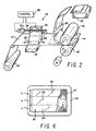
- FIG. 2 A schematic diagram of an imaging apparatus in accordance with the invention can be seen by reference to Fig. 2.
- imaging sheet is intended to include the imaging material described herein, whether processed in the form of a continuous web, individual cut sheets, or some other form.
- the apparatus shown in Fig. 2 uses an imaging set of the two-part form, wherein a separate sheet carries the developer layer, with the finished image being produced on the receiver sheet.
- the particular apparatus shown in Fig. 2 is intended for use with a web of imaging sheet material 10, such web being initially held within. a storage roll 34.
- the material 10 passes from storage roll 34 into an exposure station 36 where the material is held on a supportive platen 38.
- the exposure source 40 is mounted above the platen 38, and exposure radiation exposes web 10 in accordance with the image information.
- the source 40 is a fiber-optic cathode ray tube (FOCRT), described in detail below, whereby a full color image may be made using the imaging media.
- FOCRT fiber-optic cathode ray tube
- the capsule-coated side of web 10 is placed in contact, or closely thereto, with the faceplate of the FOCRT.
- the exposure system for the imaging material can be seen in greater detail by reference to Fig. 3.
- the exposure source 40 is a fiber-optic cathode ray tube (FOCRT) which comprises a conventional tube housing 50, electron gun 52 and deflection coils 54.
- a faceplate 56 is positioned at the target end of the FOCRT, and comprises a closely packed array of short parallel optical fibers. Coated onto the inside surface of faceplate 56 are phosphor coatings 58.
- Coatings 58 comprise three separate coatings 60, 62 and 64. Each is stimulated by the electron beam of the FOCRT, and phosphoresces in response thereto. However, each coating 60, 62 and 64 produces a separate color, i.e., red, blue or green, thereby accounting for the three color components of a color image.
- the control system for the FOCRT includes an image source 66 which may be a means for computer generating images, an image scanner such as a CCD device, or any other appropriate source of input image data.
- Data from image source 66 is directed to an image processor 68, which may perform various processing techniques on the image to enhance its appearance and place the data into an appropriate form for output to the video generator system 70.
- Video generator system 70 provides three control outputs. The first is passed to a video amp 72 and then to electron gun 52, and controls the modulation of the electron beam produced by the FOCRT. A second control output is formatted at 74 to provide proper signals for beam control and synchronization. These signals, after being directed through amp 76, are used to control the deflection coils 54 so as to properly steer the electron beam to cause it to scan the surface of the phosphor coatings 58.
- relative movement at a fixed rate between the FOCRT 40 and the imaging material is caused while the image is being exposed.
- the image is caused to scroll at the same rate over each of the three phosphor coatings 60, 62 and 64 so that there is no relative movement between a line of the image appearing on the FOCRT and a corresponding line exposed on the media.
- video generator system 70 provides a third control output directed to a motor controller 78.
- the motor controller signal is applied to a servo motor 82 which, through a lead screw 84 or other appropriate means, causes movement of the FOCRT 40.
- motor 82 and lead screw 84 under control of the control means 86 as described in connection with Fig. 3, causes movement of FOCRT 40 as indicated by arrows 88.
- the web 10 is therefore held stationary during the exposure operation.
- control means 86 may be seen by reference to U.S. patent No. 4,309,720, the disclosure of which is hereby incorporated by reference.
- FOCRT 40 may be held stationary, with the web 10 advanced synchronously with the scrolling of the image components over the phosphor coatings.
- each coating 60, 62 and 64 may be made large enough to display the complete image, whereby exposure may take place wit!lout scrolling of the images across the coatings.
- the coatings 60, 62 and 64 may be overlapped to form a single, multi-color coating, whereby a full-color image may be exposed at one time.
- the imaging material used herein tends to exhibit an effect known as short time-scale reciprocity failure. While one would expect that the imaging material would exhibit a substantially linear relationship between exposure time and exposure intensity, at short exposure times, the material in fact shows a dramatic loss in sensitivity. One approach to minimizing this effect is to lengthen the time of exposure.
- the different color microcapsules exhibit reciprocity failure to differing degrees, and at different threshold exposure intensities. Our system allows us to compensate for this effect by varying the widths of the coating stripes formed on the inside surface of the FOCRT faceplate 56.
- each of the coatings 60, 62 and 64 are of a width a, b and c, respectively. While in one embodiment, these widths may be equal, it is not necessary that they be so, due to the scrolling manner in which the image information is displayed for exposing the media. For example, if coating 60 was used to provide the red color component, and if width a were made larger than widths b and c, the total exposure energy applied to the imaging web for the red color component could be increased, provided that the intensity of the electron beam (and hence the intensity of the phosphorescence of the coating) remain the same.
- the intensity of the exposure could be reduced, while the exposure time would be increased as a result of the widened coating, thereby resulting in an exposure energy which is equal to that for the other color components, but at a reduced intensity.
- either approach may be useful in overcoming the effects of short time-scale reciprocity failure.
- the width of the coating for the red color component may be formed to be approximately 400% of the width of the coatings used for the blue and green components.
- a test image was formed using an apparatus such as that described herein, wherein 24 bits per dot of light modulation onto a continuous tone microencapsulated imaging material was used.
- Fig. 5 illustrates the system response by showing the manner in which input image data was remapped for a linear reflective scale on the output image.
- the exemplary system using a single beam CRT required a three minute total exposure time for an A4 size image. Two-thirds of the exposure time was spent in exposing the red component:
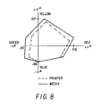
- Fig. 8 illustrates the colour gamut of both the imaging material and the exemplary colour printer.
Landscapes
- Physics & Mathematics (AREA)
- General Physics & Mathematics (AREA)
- Photographic Developing Apparatuses (AREA)
- Printers Or Recording Devices Using Electromagnetic And Radiation Means (AREA)
- Photosensitive Polymer And Photoresist Processing (AREA)
- Projection-Type Copiers In General (AREA)
Applications Claiming Priority (2)
| Application Number | Priority Date | Filing Date | Title |
|---|---|---|---|
| US422923 | 1989-10-17 | ||
| US07/422,923 US5049902A (en) | 1989-10-17 | 1989-10-17 | System for recording an image |
Publications (2)
| Publication Number | Publication Date |
|---|---|
| EP0424123A2 true EP0424123A2 (de) | 1991-04-24 |
| EP0424123A3 EP0424123A3 (en) | 1991-10-09 |
Family
ID=23676968
Family Applications (1)
| Application Number | Title | Priority Date | Filing Date |
|---|---|---|---|
| EP19900311398 Withdrawn EP0424123A3 (en) | 1989-10-17 | 1990-10-17 | Image recording |
Country Status (4)
| Country | Link |
|---|---|
| US (1) | US5049902A (de) |
| EP (1) | EP0424123A3 (de) |
| JP (1) | JPH03140941A (de) |
| KR (1) | KR100189664B1 (de) |
Cited By (1)
| Publication number | Priority date | Publication date | Assignee | Title |
|---|---|---|---|---|
| EP0884646A3 (de) * | 1997-06-10 | 1999-09-15 | Seiko Instruments Inc. | Drucker, Drucksystem und Druckverfahen mit einem Druckpapier welches lichtempfindliche Mikrokapseln enthält |
Families Citing this family (15)
| Publication number | Priority date | Publication date | Assignee | Title |
|---|---|---|---|---|
| US5818495A (en) * | 1992-11-12 | 1998-10-06 | Eastman Kodak Company | CRT printer for lenticular photographs |
| US5917548A (en) * | 1996-08-26 | 1999-06-29 | Eastman Kodak Company | Electronic camera having a printer for providing improved hard copy images |
| US5894326A (en) * | 1996-08-26 | 1999-04-13 | Eastman Kodak Company | Electronic camera having a printer |
| US6016189A (en) * | 1996-09-25 | 2000-01-18 | Brother Kogyo Kabushiki Kaisha | Portable image forming apparatus using photosensitive recording medium |
| US5715234A (en) * | 1996-12-16 | 1998-02-03 | Eastman Kodak Company | Electronic camera and associated printer which uses a display image |
| US5742861A (en) * | 1997-01-08 | 1998-04-21 | Eastman Kodak Company | Electronic camera and associated printer which uses a display image |
| US5715493A (en) * | 1997-01-08 | 1998-02-03 | Eastman Kodak Company | Apparatus and electronic camera and associated printer with light tight storage receptacle |
| US5715492A (en) * | 1997-01-31 | 1998-02-03 | Eastman Kodak Company | Electronic camera and associated printer with light shutter |
| US5970215A (en) * | 1997-04-08 | 1999-10-19 | Eastman Kodak Company | Printing variable density pixels on a photosensitive medium |
| US5996793A (en) * | 1997-04-15 | 1999-12-07 | Cycolor Systems Co., Ltd. | Method of storing and kit containing dry image-forming material |
| US5860036A (en) * | 1997-06-10 | 1999-01-12 | Eastman Kodak Company | Controlling display useable in printers |
| US5949469A (en) * | 1997-06-10 | 1999-09-07 | Eastman Kodak Co | Fluorescent light source for liquid crystal display printing |
| US5835809A (en) * | 1997-06-10 | 1998-11-10 | Eastman Kodak Company | Filter for correcting for fluorescent light in color printing |
| US6016157A (en) * | 1997-08-12 | 2000-01-18 | Eastman Kodak Company | Printer using multiple light sources and monochrome LCD |
| US5822637A (en) * | 1997-09-30 | 1998-10-13 | Eastman Kodak Company | Electronic camera and attachable printer |
Family Cites Families (10)
| Publication number | Priority date | Publication date | Assignee | Title |
|---|---|---|---|---|
| US4309720A (en) * | 1976-06-03 | 1982-01-05 | Tektronix, Inc. | Apparatus and method for producing an image on a sensitized surface |
| US4399209A (en) * | 1981-11-12 | 1983-08-16 | The Mead Corporation | Transfer imaging system |
| US4440846A (en) * | 1981-11-12 | 1984-04-03 | Mead Corporation | Photocopy sheet employing encapsulated radiation sensitive composition and imaging process |
| US4842976A (en) * | 1982-01-18 | 1989-06-27 | Mead Corp. | Color image-forming process |
| US4576891A (en) * | 1984-06-15 | 1986-03-18 | The Mead Corporation | Photosensitive microcapsules useful in polychromatic imaging having radiation absorber |
| JPS62290561A (ja) * | 1986-06-10 | 1987-12-17 | Seiko Instr & Electronics Ltd | カラ−プリンタ |
| US4965592A (en) * | 1987-05-21 | 1990-10-23 | Brother Kogyo Kabushiki Kaisha | Image processing apparatus for reproducing images on projector screen and photosensitive medium |
| US4804611A (en) * | 1987-06-24 | 1989-02-14 | The Mead Corporation | Method for reducing short time-scale reciprocity failure effects of a microencapsulated acrylate system |
| US4923779A (en) * | 1989-01-09 | 1990-05-08 | The Mead Corporation | Color-correcting exposure system for a photosensitive media |
| US4943827A (en) * | 1989-04-27 | 1990-07-24 | The Mead Corporation | Method and apparatus for controlling exposure of an imaging sheet |
-
1989
- 1989-10-17 US US07/422,923 patent/US5049902A/en not_active Expired - Lifetime
-
1990
- 1990-10-16 KR KR1019900016432A patent/KR100189664B1/ko not_active Expired - Fee Related
- 1990-10-17 JP JP2278839A patent/JPH03140941A/ja active Pending
- 1990-10-17 EP EP19900311398 patent/EP0424123A3/en not_active Withdrawn
Cited By (2)
| Publication number | Priority date | Publication date | Assignee | Title |
|---|---|---|---|---|
| EP0884646A3 (de) * | 1997-06-10 | 1999-09-15 | Seiko Instruments Inc. | Drucker, Drucksystem und Druckverfahen mit einem Druckpapier welches lichtempfindliche Mikrokapseln enthält |
| US6229558B1 (en) | 1997-06-10 | 2001-05-08 | Seiko Instruments Inc. | Printer, printing system, and printing method using print paper with photosensitive microcapsules applied thereto |
Also Published As
| Publication number | Publication date |
|---|---|
| JPH03140941A (ja) | 1991-06-14 |
| KR100189664B1 (ko) | 1999-06-01 |
| US5049902A (en) | 1991-09-17 |
| KR910008484A (ko) | 1991-05-31 |
| EP0424123A3 (en) | 1991-10-09 |
Similar Documents
| Publication | Publication Date | Title |
|---|---|---|
| US5049902A (en) | System for recording an image | |
| CA1199514A (en) | Transfer imaging system | |
| EP0162664B1 (de) | Aufzeichnungssysteme, Verfahren zur Aufzeichnung und verwendbare Entwicklerblätter darin | |
| USRE37257E1 (en) | Transfer imaging system | |
| US4587194A (en) | Photosensitive material employing microcapsules having different photographic speeds | |
| US4440846A (en) | Photocopy sheet employing encapsulated radiation sensitive composition and imaging process | |
| CA1261666A (en) | Photosensitive imaging system employing oil- containing microcapsules | |
| US4562137A (en) | Photosensitive material employing encapsulated radiation sensitive composition | |
| JPH0451818B2 (de) | ||
| US4532200A (en) | Photosensitive imaging material employing encapsulated radiation sensitive composition having improved toe speed | |
| US4903991A (en) | Document security system | |
| US4535050A (en) | Peeling development of photosensitive materials employing microencapsulated radiation sensitive compositions | |
| US4943827A (en) | Method and apparatus for controlling exposure of an imaging sheet | |
| EP0157783B1 (de) | Thermische entwicklung lichtempfindlicher materialien mittels strahlungsempfindlicher mikrokapselnzusammensetzungen | |
| US4865943A (en) | Method for forming images using free flowing photosensitive microcapsules | |
| US4663266A (en) | Thermal development of photosensitive materials employing microencapsulated radiation sensitive compositions | |
| US5053309A (en) | Color image-forming process | |
| CA1262650A (en) | Photosensitive microcapsules containing photo- inhibitor precursor and imaging material employing the same | |
| US4780391A (en) | Color-image recording material | |
| US4840866A (en) | Microcapsule imaging system having improved dynamic range | |
| EP0283314A2 (de) | Entwicklerblatt und dasselbe verwendendes Aufzeichnungsverfahren | |
| US4873168A (en) | Imaging system utilizing heat treatment | |
| US4957843A (en) | Prevention of short time scale reciprocity failure by viscosity control | |
| EP0378373B1 (de) | Photohärtbare Zusammensetzungen und ihre Verwendung zur Herstellung von Bildern | |
| US4935329A (en) | Negative working imaging process employing photosensitive microcapsules |
Legal Events
| Date | Code | Title | Description |
|---|---|---|---|
| PUAI | Public reference made under article 153(3) epc to a published international application that has entered the european phase |
Free format text: ORIGINAL CODE: 0009012 |
|
| AK | Designated contracting states |
Kind code of ref document: A2 Designated state(s): DE FR GB |
|
| PUAL | Search report despatched |
Free format text: ORIGINAL CODE: 0009013 |
|
| AK | Designated contracting states |
Kind code of ref document: A3 Designated state(s): DE FR GB |
|
| 17P | Request for examination filed |
Effective date: 19920409 |
|
| STAA | Information on the status of an ep patent application or granted ep patent |
Free format text: STATUS: THE APPLICATION HAS BEEN WITHDRAWN |
|
| 18W | Application withdrawn |
Withdrawal date: 19940317 |