EP0424149A1 - Accéléromètre capacitif - Google Patents
Accéléromètre capacitif Download PDFInfo
- Publication number
- EP0424149A1 EP0424149A1 EP90311442A EP90311442A EP0424149A1 EP 0424149 A1 EP0424149 A1 EP 0424149A1 EP 90311442 A EP90311442 A EP 90311442A EP 90311442 A EP90311442 A EP 90311442A EP 0424149 A1 EP0424149 A1 EP 0424149A1
- Authority
- EP
- European Patent Office
- Prior art keywords
- electrode
- electrically conductive
- capacitor
- substrate
- electrode member
- Prior art date
- Legal status (The legal status is an assumption and is not a legal conclusion. Google has not performed a legal analysis and makes no representation as to the accuracy of the status listed.)
- Granted
Links
- 239000003990 capacitor Substances 0.000 claims abstract description 30
- 239000000758 substrate Substances 0.000 claims abstract description 19
- 125000006850 spacer group Chemical group 0.000 claims abstract description 14
- 239000004020 conductor Substances 0.000 claims description 6
- 230000008878 coupling Effects 0.000 claims description 2
- 238000010168 coupling process Methods 0.000 claims description 2
- 238000005859 coupling reaction Methods 0.000 claims description 2
- 230000001133 acceleration Effects 0.000 abstract description 18
- 238000007789 sealing Methods 0.000 abstract description 5
- 238000001259 photo etching Methods 0.000 abstract description 3
- 238000013016 damping Methods 0.000 description 6
- 239000004593 Epoxy Substances 0.000 description 4
- 238000001465 metallisation Methods 0.000 description 4
- 238000000034 method Methods 0.000 description 4
- 239000000919 ceramic Substances 0.000 description 3
- 230000001939 inductive effect Effects 0.000 description 3
- 238000004519 manufacturing process Methods 0.000 description 3
- 238000012986 modification Methods 0.000 description 3
- 230000004048 modification Effects 0.000 description 3
- 229920006332 epoxy adhesive Polymers 0.000 description 2
- RYGMFSIKBFXOCR-UHFFFAOYSA-N Copper Chemical compound [Cu] RYGMFSIKBFXOCR-UHFFFAOYSA-N 0.000 description 1
- 239000000853 adhesive Substances 0.000 description 1
- 230000001070 adhesive effect Effects 0.000 description 1
- 238000005219 brazing Methods 0.000 description 1
- 229910052802 copper Inorganic materials 0.000 description 1
- 239000010949 copper Substances 0.000 description 1
- 230000007613 environmental effect Effects 0.000 description 1
- 239000011521 glass Substances 0.000 description 1
- 239000012212 insulator Substances 0.000 description 1
- 238000003698 laser cutting Methods 0.000 description 1
- 239000000463 material Substances 0.000 description 1
- 239000002184 metal Substances 0.000 description 1
- 229910052751 metal Inorganic materials 0.000 description 1
- 239000000843 powder Substances 0.000 description 1
- 229910000679 solder Inorganic materials 0.000 description 1
- 238000005476 soldering Methods 0.000 description 1
- 230000002277 temperature effect Effects 0.000 description 1
- 238000003466 welding Methods 0.000 description 1
Images


Classifications
-
- G—PHYSICS
- G01—MEASURING; TESTING
- G01P—MEASURING LINEAR OR ANGULAR SPEED, ACCELERATION, DECELERATION, OR SHOCK; INDICATING PRESENCE, ABSENCE, OR DIRECTION, OF MOVEMENT
- G01P15/00—Measuring acceleration; Measuring deceleration; Measuring shock, i.e. sudden change of acceleration
- G01P15/02—Measuring acceleration; Measuring deceleration; Measuring shock, i.e. sudden change of acceleration by making use of inertia forces using solid seismic masses
- G01P15/08—Measuring acceleration; Measuring deceleration; Measuring shock, i.e. sudden change of acceleration by making use of inertia forces using solid seismic masses with conversion into electric or magnetic values
- G01P15/125—Measuring acceleration; Measuring deceleration; Measuring shock, i.e. sudden change of acceleration by making use of inertia forces using solid seismic masses with conversion into electric or magnetic values by capacitive pick-up
Definitions
- This invention relates to accelerometers for measuring acceleration by measuring the capacitance of a capacitor, the capacitance of which varies with change in acceleration.
- Prior art capacitive accelerometers generally utilize an inertial beam and air damping. Examples of typical prior art accelerometers are shown in patents 3,339,419 of Wilcox, 3,709,042 of Lee, 3,089,343 of Rule, 3,132,521 of Krupick, 3,240,073 of Pitzer, 3,292,059 of Woods, 3,267,740 of Stedman, 4,333,029 of Kolm and 3,988,620 of McDavid.
- the prior art capacitive accelerometers have generally been complex, resulting in high cost of manufacture. It is therefore apparent that the art always seeks capacitive accelerometers which can be produced in a less costly manner.
- a capacitive acceleration sensor which uses a common printed wiring board or substrate as both one of the plates of the capacitive transducer and the wiring connections thereto.
- the sensor utilizes a single variable capacitor and a fixed reference capacitor.
- the sensor is designed to measure low "g” accelerations, but can be easily modified to measure higher "g”s.
- An acceleration input moves a capacitor plate producing a change in capacitance.
- the sensor utilizes an electronic signal conditioner which accurately converts the capacitance output to a voltage signal.
- the transducer and electronics are laid out on a printed wiring board making up a complete sensor package. The result is a low "g" acceleration sensor featuring accurate DC performance.
- the capacitor comprises a fixed electrode on the PWB and a movable acceleration responsive electrode which is secured to a support by a conductive resilient member, the support being coupled to an electrically conductive region on the PWB which is spaced from the fixed electrode by a guard ring to minimize stray charge passing between the capacitor electrodes.
- the movable capacitor electrode is supported at its center region by a pair of electrically conductive members, one of which is coupled to an electrically conductive region on a substrate spaced from the movable electrode by a sealing spacer.
- the fixed capacitor electrode is disposed either on the same substrate or on a separate substrate on the opposite side of the movable electrode spaced from the movable electrode by a sealing spacer and having the fixed capacitor electrode thereon.
- the movable capacitor electrode can be secured at its center or at an edge.
- the movable electrode or seismic disk can be produced by stamping and/or photoetching and provide a single element where plural elements were previously required.
- FIGURES and 2 there is shown the capacitive transducer 13 on a metallized printed wiring board (PWB) having electronics 14 thereon in accordance with the present invention.
- the PWB can be formed of ceramic, epoxy or other well known material from which PWBs are generally fabricated.
- Metallization on the printed wiring board 1 acts as the fixed capacitor plate of the transducer.
- the metallization on the PWB preferably of copper, includes a source ring 2 which is generally connected to an oscillator, a detect region 3 within the source ring connected to the electronics 14 and a guard ring 4 surrounding the detect region.
- the detect region 3 picks up the AC signal from the source ring 2 connected to the beam mass support structure and the charge collected thereon is an indication of the instantaneous capacitance of the capacitor.
- the guard region 4 minimizes surface currents from the source ring 2, which is oscillating in voltage, to the detect region 3.
- a preform spacer 5 is placed on the source ring 2 and provides electrical contact to the spring/mass element 6.
- the spacer 5 can be an electrical conductor such as, for example, an epoxy or it can be an insulator with an electrical conductor disposed thereacross.
- the spring/mass element 6 is composed of a support ring 7 of electrically conductive material, an electrically conductive beam 8 which acts as the spring of the system and an electrically conductive mass 9 which deflects under a given acceleration, inducing a capacitance change relative to the detect region 3.
- the beam 8 is secured to the support ring 7 and conductive mass 9.
- the support ring 7 and conductive mass 9 are generally of the same thickness and lie generally in the same plane.
- the spring/mass element 6 is assembled as a unit on a flat surface with a low stress inducing bonding means (solder, brazed, epoxy or other adhesive, spot weld or laser weld). The flatness of the spring/mass element 6 is unaffected by beam variations.
- a second preform electrically conductive epoxy spacer 10 is placed on the support ring 7 and spaces a section of double sided metallized printed wiring board therefrom. This section of PWB is optional and assists in shielding from stray capacitances by being part of the overall ground plane which contains the other side of the printed wiring board.
- the PWB 1 also contains electronic circuitry 14 thereon to which the capacitor is coupled.
- the above described PWB can be modified to have electronics on one surface thereof and the transducer on a different or opposing surface thereof.
- the system as described above displays essentially no temperature effect to the first order when the temperature coefficient of expansion of the printed wiring board 1, the spacers 5 and 10, the board 11 and the support ring 7 are matched.
- the fact that a single beam 8 is used permits the conductive mass 9 to move in all directions, thereby minimizing the requirement that the beam or mass be temperature matched to the remaining components.
- the device as described above also provides protection against overload by providing stops by the upper and lower circuit board sections 1 and 11 which prevent excess vertical movement by the electrically conductive mass 9.
- Squeeze film damping is provided by the circular flat mass moving relative to the circuit boards.
- the spacing between the mass and overload stops is preferably less than or equal to 0.005 inches to obtain significant initial capacitance changes in capacitance and damping.
- the beam and/or mass dimensions can be modified to change the level of accelerations sensed and the frequency range desired. A differential capacitance mode could be obtained with slight modifications to the sensor if more signal is desired.
- the sensor is contained on a single printed wiring board, can be assembled with automated machinery and provides for simple edge-card connection along the pads 12 on the PWB. The whole assembly can be overmolded for environmental protection.
- the source ring 2 is coupled through the spacer 5 and the support ring 7 to the conductive mass 9 as well as to the electronics 14.
- the detect region 3 is also coupled to the electronics 14. Accordingly, as the conductive mass 9 moves due to acceleration and changes thereof, the capacitive coupling between the mass and the detect region 5 changes, resulting in a change in the charge on the detect region, this change being detected by the electronics to provide a readout related to acceleration.
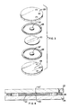
- the device comprises a thin, supported diaphragm or seismic disk 21 which acts as the seismic mass and spring of the accelerometer system.
- Supports 22 and 22, of conductive epoxy adhesive with glass spacers are electrically coupled to the diaphragm 21 and are disposed on opposite sides of the diaphragm to control capacitor function.
- An upper ceramic plate 23 with metallization thereon acts as a mechanical stop as well as a fixed capacitor plate.
- the lower ceramic plate 24 also acts as a mechanical stop. Both plates 23 and 24 combined with the flexible diaphragm 21 determine the damping ratio of the system.
- Damping is provided by viscous air flow between the moving diaphragm 21 and plates 23 and 24 (squeeze film damping).
- the sealing of the device is accomplished with a non-conductive epoxy adhesive 25 around the periphery of the plates 23 and 24.
- the electronics (not shown) are connected to source (capacitor plate), detect (diaphragm) and guard ring (to protect detect from stray surface currents). Connection to the capacitor is made by contact to the metallization on the plate 23 and to a conductor on the plate 23 or 24 which is coupled to one of the supports 22 or 22′.
- the device allows for little stray capacitance with this integrated electronic configuration and provides great overload protection with the plates acting as mechanical stops.
- the diaphragm dimensions can be changed to add flexibility to the level of accelerations sensed and the frequency range desired.
- FIGURES 5a and 5b are illustrations of other configurations for securing the seismic disc as well as the disk configurations. Seismic disks of the type shown in FIGURES 3, 4, 5a and 5b can be produced by stamping and/or photoetching and provide a single element where plural elements were previously required.
- FIGURES 6a, 6b and 6c there is shown a process for fabrication of the beam, mass and support structure of the above described embodiment of FIGURES 1 and 2 as single units or as an array.
- the mass and support structure can be made as a sintered powder metal part with interconnecting tabs. This part can then be subsequently ground on both sides since the mass and support must be of substantially the same equal thickness and have substantially parallel or coplanar surfaces on both sides.
- a beam can then be attached via a low stress inducing process, e.g., laser welding, brazing or reflow soldering and then the interconnecting tabs can be separated by laser cutting.
Landscapes
- Physics & Mathematics (AREA)
- General Physics & Mathematics (AREA)
- Pressure Sensors (AREA)
Applications Claiming Priority (2)
| Application Number | Priority Date | Filing Date | Title |
|---|---|---|---|
| US07/423,922 US5092174A (en) | 1989-10-19 | 1989-10-19 | Capacitance accelerometer |
| US423922 | 1989-10-19 |
Publications (2)
| Publication Number | Publication Date |
|---|---|
| EP0424149A1 true EP0424149A1 (fr) | 1991-04-24 |
| EP0424149B1 EP0424149B1 (fr) | 1995-01-04 |
Family
ID=23680719
Family Applications (1)
| Application Number | Title | Priority Date | Filing Date |
|---|---|---|---|
| EP90311442A Expired - Lifetime EP0424149B1 (fr) | 1989-10-19 | 1990-10-18 | Accéléromètre capacitif |
Country Status (4)
| Country | Link |
|---|---|
| US (1) | US5092174A (fr) |
| EP (1) | EP0424149B1 (fr) |
| JP (1) | JPH03183963A (fr) |
| DE (1) | DE69015766T2 (fr) |
Cited By (4)
| Publication number | Priority date | Publication date | Assignee | Title |
|---|---|---|---|---|
| EP0547742A1 (fr) * | 1991-12-19 | 1993-06-23 | Motorola, Inc. | Accéléromètre à trois axes |
| EP0604212A1 (fr) * | 1992-12-25 | 1994-06-29 | Nec Corporation | Capteur à semi-conducteur pour mesurer une quantité physique |
| GB2312959A (en) * | 1996-05-10 | 1997-11-12 | Secr Defence | Method of making electrodes for accelerometers and other sensors |
| EP1340985A1 (fr) * | 2002-02-28 | 2003-09-03 | Delphi Technologies, Inc. | Accéléromètre angulaire équilibre |
Families Citing this family (37)
| Publication number | Priority date | Publication date | Assignee | Title |
|---|---|---|---|---|
| US5253526A (en) * | 1990-05-30 | 1993-10-19 | Copal Company Limited | Capacitive acceleration sensor with free diaphragm |
| US5313835A (en) * | 1991-12-19 | 1994-05-24 | Motorola, Inc. | Integrated monolithic gyroscopes/accelerometers with logic circuits |
| JPH06186249A (ja) * | 1992-12-16 | 1994-07-08 | Mitsubishi Electric Corp | 容量式加速度検出装置 |
| US6026677A (en) * | 1993-10-01 | 2000-02-22 | Hysitron, Incorporated | Apparatus for microindentation hardness testing and surface imaging incorporating a multi-plate capacitor system |
| US5553486A (en) * | 1993-10-01 | 1996-09-10 | Hysitron Incorporated | Apparatus for microindentation hardness testing and surface imaging incorporating a multi-plate capacitor system |
| US5576483A (en) * | 1993-10-01 | 1996-11-19 | Hysitron Incorporated | Capacitive transducer with electrostatic actuation |
| US5661235A (en) * | 1993-10-01 | 1997-08-26 | Hysitron Incorporated | Multi-dimensional capacitive transducer |
| US5469632A (en) * | 1994-04-08 | 1995-11-28 | Westinghouse Electric Corp. | Capacitive angle sensor employing a vertical cantilever beam |
| US5546805A (en) * | 1994-08-12 | 1996-08-20 | Coyote Engineering Services, Inc. | Angle and angular acceleration sensors |
| US5581035A (en) | 1994-08-29 | 1996-12-03 | The Charles Stark Draper Laboratory, Inc. | Micromechanical sensor with a guard band electrode |
| US5646348A (en) | 1994-08-29 | 1997-07-08 | The Charles Stark Draper Laboratory, Inc. | Micromechanical sensor with a guard band electrode and fabrication technique therefor |
| US5535626A (en) * | 1994-12-21 | 1996-07-16 | Breed Technologies, Inc. | Sensor having direct-mounted sensing element |
| US5710376A (en) * | 1995-12-22 | 1998-01-20 | International Business Machines Corporation | Charged mass thin film condenser accelerometer |
| US5824902A (en) * | 1996-09-30 | 1998-10-20 | Texas Instruments Incorporated | Condition responsive sensor having a signal conditioning capacitor |
| US6257062B1 (en) | 1999-10-01 | 2001-07-10 | Delphi Technologies, Inc. | Angular Accelerometer |
| US6397762B1 (en) | 2000-06-09 | 2002-06-04 | Berco Industries, Inc. | Work table |
| US6393914B1 (en) | 2001-02-13 | 2002-05-28 | Delphi Technologies, Inc. | Angular accelerometer |
| WO2002073673A1 (fr) * | 2001-03-13 | 2002-09-19 | Rochester Institute Of Technology | Commutateur micro-electromecanique et un procede de sa mise en oeuvre et de sa fabrication |
| WO2002097865A2 (fr) * | 2001-05-31 | 2002-12-05 | Rochester Institute Of Technology | Soupapes, agitateurs et pompes microfluidiques et procedes correspondants |
| US7211923B2 (en) | 2001-10-26 | 2007-05-01 | Nth Tech Corporation | Rotational motion based, electrostatic power source and methods thereof |
| US7378775B2 (en) * | 2001-10-26 | 2008-05-27 | Nth Tech Corporation | Motion based, electrostatic power source and methods thereof |
| US6854330B2 (en) | 2001-10-26 | 2005-02-15 | Nth Tech Corporation | Accelerometer and methods thereof |
| US6761070B2 (en) | 2002-01-31 | 2004-07-13 | Delphi Technologies, Inc. | Microfabricated linear accelerometer |
| US6666092B2 (en) | 2002-02-28 | 2003-12-23 | Delphi Technologies, Inc. | Angular accelerometer having balanced inertia mass |
| US7217582B2 (en) * | 2003-08-29 | 2007-05-15 | Rochester Institute Of Technology | Method for non-damaging charge injection and a system thereof |
| US7287328B2 (en) * | 2003-08-29 | 2007-10-30 | Rochester Institute Of Technology | Methods for distributed electrode injection |
| JP4228927B2 (ja) * | 2004-02-04 | 2009-02-25 | 株式会社デンソー | 加速度センサモジュール |
| US8581308B2 (en) * | 2004-02-19 | 2013-11-12 | Rochester Institute Of Technology | High temperature embedded charge devices and methods thereof |
| US7194376B2 (en) * | 2004-04-27 | 2007-03-20 | Delphi Technologies, Inc. | Circuit and method of processing multiple-axis sensor output signals |
| US20050235751A1 (en) * | 2004-04-27 | 2005-10-27 | Zarabadi Seyed R | Dual-axis accelerometer |
| US7250322B2 (en) * | 2005-03-16 | 2007-07-31 | Delphi Technologies, Inc. | Method of making microsensor |
| US20060207327A1 (en) * | 2005-03-16 | 2006-09-21 | Zarabadi Seyed R | Linear accelerometer |
| US20070074731A1 (en) * | 2005-10-05 | 2007-04-05 | Nth Tech Corporation | Bio-implantable energy harvester systems and methods thereof |
| EP1994360A4 (fr) * | 2006-03-13 | 2012-03-14 | Asylum Research Corp | Nanopénétrateur |
| JP5527017B2 (ja) * | 2010-05-27 | 2014-06-18 | セイコーエプソン株式会社 | 素子構造体、慣性センサーおよび電子機器 |
| US8656778B2 (en) * | 2010-12-30 | 2014-02-25 | Rosemount Aerospace Inc. | In-plane capacitive mems accelerometer |
| EP3147258A1 (fr) * | 2015-09-22 | 2017-03-29 | AT & S Austria Technologie & Systemtechnik Aktiengesellschaft | Panneau de connexion pour composants électroniques |
Citations (4)
| Publication number | Priority date | Publication date | Assignee | Title |
|---|---|---|---|---|
| DE3201198A1 (de) * | 1981-01-29 | 1982-09-02 | ASEA AB, 72183 Västerås | "kapazitiver geber zur anzeige oder registrierung von messgroessen" |
| US4435737A (en) * | 1981-12-16 | 1984-03-06 | Rockwell International Corporation | Low cost capacitive accelerometer |
| US4694687A (en) * | 1986-04-17 | 1987-09-22 | Vericom Corporation | Vehicle performance analyzer |
| DE3719037A1 (de) * | 1986-07-10 | 1988-02-11 | Litton Systems Inc | Vibrierender beschleunigungsmesser-multisensor |
Family Cites Families (2)
| Publication number | Priority date | Publication date | Assignee | Title |
|---|---|---|---|---|
| US3709042A (en) * | 1969-05-14 | 1973-01-09 | S Lee | Capacitance accelerometer |
| CH642461A5 (fr) * | 1981-07-02 | 1984-04-13 | Centre Electron Horloger | Accelerometre. |
-
1989
- 1989-10-19 US US07/423,922 patent/US5092174A/en not_active Expired - Fee Related
-
1990
- 1990-10-18 DE DE69015766T patent/DE69015766T2/de not_active Expired - Fee Related
- 1990-10-18 EP EP90311442A patent/EP0424149B1/fr not_active Expired - Lifetime
- 1990-10-19 JP JP2281738A patent/JPH03183963A/ja active Pending
Patent Citations (4)
| Publication number | Priority date | Publication date | Assignee | Title |
|---|---|---|---|---|
| DE3201198A1 (de) * | 1981-01-29 | 1982-09-02 | ASEA AB, 72183 Västerås | "kapazitiver geber zur anzeige oder registrierung von messgroessen" |
| US4435737A (en) * | 1981-12-16 | 1984-03-06 | Rockwell International Corporation | Low cost capacitive accelerometer |
| US4694687A (en) * | 1986-04-17 | 1987-09-22 | Vericom Corporation | Vehicle performance analyzer |
| DE3719037A1 (de) * | 1986-07-10 | 1988-02-11 | Litton Systems Inc | Vibrierender beschleunigungsmesser-multisensor |
Cited By (6)
| Publication number | Priority date | Publication date | Assignee | Title |
|---|---|---|---|---|
| EP0547742A1 (fr) * | 1991-12-19 | 1993-06-23 | Motorola, Inc. | Accéléromètre à trois axes |
| EP0604212A1 (fr) * | 1992-12-25 | 1994-06-29 | Nec Corporation | Capteur à semi-conducteur pour mesurer une quantité physique |
| US5431050A (en) * | 1992-12-25 | 1995-07-11 | Nec Corporation | Semiconductor sensor with nested weight portions for converting physical quantity into twisting strains |
| GB2312959A (en) * | 1996-05-10 | 1997-11-12 | Secr Defence | Method of making electrodes for accelerometers and other sensors |
| EP1340985A1 (fr) * | 2002-02-28 | 2003-09-03 | Delphi Technologies, Inc. | Accéléromètre angulaire équilibre |
| US6718826B2 (en) | 2002-02-28 | 2004-04-13 | Delphi Technologies, Inc. | Balanced angular accelerometer |
Also Published As
| Publication number | Publication date |
|---|---|
| EP0424149B1 (fr) | 1995-01-04 |
| DE69015766T2 (de) | 1995-05-11 |
| DE69015766D1 (de) | 1995-02-16 |
| US5092174A (en) | 1992-03-03 |
| JPH03183963A (ja) | 1991-08-09 |
Similar Documents
| Publication | Publication Date | Title |
|---|---|---|
| US5092174A (en) | Capacitance accelerometer | |
| EP0459939B2 (fr) | Capteur d'accélération capacitif à membrane libre | |
| US5150275A (en) | Capacitive pressure sensor | |
| US4435737A (en) | Low cost capacitive accelerometer | |
| US6477903B2 (en) | Force detector and acceleration detector and method of manufacturing the same | |
| US6566742B1 (en) | Structure for mounting components | |
| US7533582B2 (en) | Force detector and acceleration detector and method of manufacturing the same | |
| US4177496A (en) | Capacitive pressure transducer | |
| EP0542436B1 (fr) | Accéléromètre | |
| EP0491506B1 (fr) | Accéléromètre et procédé de fabrication | |
| US5347867A (en) | Accelerometer incorporating a driven shield | |
| US4947694A (en) | Vibrating force sensor | |
| EP1342988A2 (fr) | Capteur capacitif | |
| US6564644B1 (en) | High temperature surface mount transducer | |
| US8013403B2 (en) | Sensor apparatus for detecting variations in a dynamic quantity while suppressing detection deviations that are caused by bending deformation of a sensor chip | |
| US5792954A (en) | Condition responsive sensor | |
| EP1031837A1 (fr) | Capteurs d'accélération | |
| JP4365982B2 (ja) | 傾斜センサ | |
| US5824902A (en) | Condition responsive sensor having a signal conditioning capacitor | |
| KR100479934B1 (ko) | 저주파 진동 측정용 가속도 센서 | |
| JP2800131B2 (ja) | 加速度センサ | |
| JPH01136041A (ja) | 静電容量式荷重センサ | |
| JPH0658335U (ja) | 静電容量式圧力検出器 | |
| JP2004061435A (ja) | 静電容量式センサ | |
| JPH0526715A (ja) | 静電容量式電子秤 |
Legal Events
| Date | Code | Title | Description |
|---|---|---|---|
| PUAI | Public reference made under article 153(3) epc to a published international application that has entered the european phase |
Free format text: ORIGINAL CODE: 0009012 |
|
| AK | Designated contracting states |
Kind code of ref document: A1 Designated state(s): DE FR GB IT NL |
|
| 17P | Request for examination filed |
Effective date: 19911001 |
|
| 17Q | First examination report despatched |
Effective date: 19921216 |
|
| ITF | It: translation for a ep patent filed | ||
| GRAA | (expected) grant |
Free format text: ORIGINAL CODE: 0009210 |
|
| AK | Designated contracting states |
Kind code of ref document: B1 Designated state(s): DE FR GB IT NL |
|
| REF | Corresponds to: |
Ref document number: 69015766 Country of ref document: DE Date of ref document: 19950216 |
|
| ET | Fr: translation filed | ||
| PLBE | No opposition filed within time limit |
Free format text: ORIGINAL CODE: 0009261 |
|
| STAA | Information on the status of an ep patent application or granted ep patent |
Free format text: STATUS: NO OPPOSITION FILED WITHIN TIME LIMIT |
|
| 26N | No opposition filed | ||
| PGFP | Annual fee paid to national office [announced via postgrant information from national office to epo] |
Ref country code: GB Payment date: 20010914 Year of fee payment: 12 |
|
| PGFP | Annual fee paid to national office [announced via postgrant information from national office to epo] |
Ref country code: NL Payment date: 20010921 Year of fee payment: 12 |
|
| PGFP | Annual fee paid to national office [announced via postgrant information from national office to epo] |
Ref country code: FR Payment date: 20011005 Year of fee payment: 12 |
|
| PGFP | Annual fee paid to national office [announced via postgrant information from national office to epo] |
Ref country code: DE Payment date: 20011030 Year of fee payment: 12 |
|
| REG | Reference to a national code |
Ref country code: GB Ref legal event code: IF02 |
|
| PG25 | Lapsed in a contracting state [announced via postgrant information from national office to epo] |
Ref country code: GB Free format text: LAPSE BECAUSE OF NON-PAYMENT OF DUE FEES Effective date: 20021018 |
|
| PG25 | Lapsed in a contracting state [announced via postgrant information from national office to epo] |
Ref country code: NL Free format text: LAPSE BECAUSE OF NON-PAYMENT OF DUE FEES Effective date: 20030501 Ref country code: DE Free format text: LAPSE BECAUSE OF NON-PAYMENT OF DUE FEES Effective date: 20030501 |
|
| GBPC | Gb: european patent ceased through non-payment of renewal fee |
Effective date: 20021018 |
|
| PG25 | Lapsed in a contracting state [announced via postgrant information from national office to epo] |
Ref country code: FR Free format text: LAPSE BECAUSE OF NON-PAYMENT OF DUE FEES Effective date: 20030630 |
|
| NLV4 | Nl: lapsed or anulled due to non-payment of the annual fee |
Effective date: 20030501 |
|
| REG | Reference to a national code |
Ref country code: FR Ref legal event code: ST |
|
| PG25 | Lapsed in a contracting state [announced via postgrant information from national office to epo] |
Ref country code: IT Free format text: LAPSE BECAUSE OF NON-PAYMENT OF DUE FEES Effective date: 20051018 |