EP0424300A2 - Procédé d'élimination de trames multiples dans des réseaux en anneau à jeton - Google Patents
Procédé d'élimination de trames multiples dans des réseaux en anneau à jeton Download PDFInfo
- Publication number
- EP0424300A2 EP0424300A2 EP90480135A EP90480135A EP0424300A2 EP 0424300 A2 EP0424300 A2 EP 0424300A2 EP 90480135 A EP90480135 A EP 90480135A EP 90480135 A EP90480135 A EP 90480135A EP 0424300 A2 EP0424300 A2 EP 0424300A2
- Authority
- EP
- European Patent Office
- Prior art keywords
- frame
- frames
- ring
- station
- delimiter
- Prior art date
- Legal status (The legal status is an assumption and is not a legal conclusion. Google has not performed a legal analysis and makes no representation as to the accuracy of the status listed.)
- Granted
Links
Images





Classifications
-
- H—ELECTRICITY
- H04—ELECTRIC COMMUNICATION TECHNIQUE
- H04L—TRANSMISSION OF DIGITAL INFORMATION, e.g. TELEGRAPHIC COMMUNICATION
- H04L12/00—Data switching networks
- H04L12/28—Data switching networks characterised by path configuration, e.g. LAN [Local Area Networks] or WAN [Wide Area Networks]
- H04L12/42—Loop networks
- H04L12/427—Loop networks with decentralised control
- H04L12/433—Loop networks with decentralised control with asynchronous transmission, e.g. token ring, register insertion
Definitions
- the invention relates to communication networks in general and more particularly to a method for stripping data from a token ring network using both early token release and a multi-frame transmit mode.
- a transmitting station can release the token as soon as it completes frame transmission, thus making the token available to other stations waiting to transmit sooner than in normal token release.
- European patent application N° 90480076.0 addresses the situation where a station on the ring transmits a token immediately after sending one frame of data. Although multiple frames can be on the ring simultaneously, only one frame can be placed on the ring by a given station.
- the disclosed method for removing corrupted messages involves a check for two conditions and the occurrence of either terminates frame stripping at a receiving station. In the first test, the receiving station compares the source address of the received frame against the source address of the frame that is transmitted. If they do not match and no code violation errors are detected within the frame header, the receiving station stops its stripping operation immediately.
- the second condition disclosed for terminating the stripping operation of a receiving station is the detection of an isolated ending delimiter, i.e., an ending delimiter that was not preceded by a paired starting delimiter.
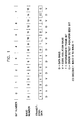
- the intermediate frame bit is also referred to as the "I-bit" and follows the unique bit pattern occurring in the first six bits of the ending delimiter.
- a one in the I-bit indicates that the frame is an intermediate frame; a zero, that the frame is the last frame in the transmit sequence.
- the data pattern of the ending delimiter and the position of the I-bit is shown in Figure 1.
- the frame counter is selec tively incremented when a frame is transmitted and selectively decremented when a frame is stripped.
- a transmit station can send frames using either a single frame mode or a multi-frame mode.
- a station can send only one frame per usable token.
- a station can send multiple frames per usable token.
- the maximum number of frames that the station can transmit is limited by the Token Holding Timer (THT) which is specified in the applicable standard.
- THT Token Holding Timer
- a transmit station In a token ring network, a transmit station is responsible for removing the frames from the ring that it has originated. This process is relatively simple in single frame mode ring using normal token release (NTR). The task becomes more complex for a token ring using early token release (ETR), particularly so when operating in a multi-frame mode. In the latter case, a transmit station has to keep track of the number of frames it has sent, so that it can strip exactly the same number of return frames during the stripping process. In addition, the transmit station has to perform other multi-frame mode administrative tasks like setting the I-bit in the ending delimiter of an intermediate frame.
- the multi-frame stripping protocol of this invention is performed by three finite state machines implemented in hardware.
- the state machines provide for termination of frame stripping operations at a source station if one or more of its transmitted frames have been corrupted when special unique combinations of conditions are detected.
- a first unique combination occurs after the transmitter has finished transmitting when the source address of a frame from another station is detected without code violation errors in the frame header and the value in the frame counter has returned to its initial value.
- a second unique combination occurs when an isolated ending delimiter is detected in the only frame placed on the ring at the transmitting station.
- a third unique combination occurs when the ending delimiter of the last frame transmitted by the source station has been received without code violation error in the I-bit, if the ending delimiter of each previously transmitted frame has been detected despite corruption in the frame header of one or more frames.
- Incoming ring data is first converted from Differential Manchester Code to Transitional Code by the Manchester-To-Transitional decoder (M/T) 12.
- M/T Manchester-To-Transitional decoder
- the decoded serial ring data is shifted into a 16-bit data deserializer 14 which deserializes the serial data stream into a parallel data stream.
- the parallel data of the data deserializer 14 is loaded into the source address comparator 40 at the necessary time to do the source address (SA) comparison.
- SA source address
- SAR source address register
- the contents of the SAR 30 are updated by the adapter microcode during each transmit frame through an internal data and address bus 32. Also tapping at the parallel output of data deserializer 14 are different hardware detectors 16, 18, 20, 22, 24, 26 which are needed to detect the different delimiters and error conditions required by the three finite state machines (FSM) 50, 60, 70. All the detector outputs are connected to the FSM through an internal control bus 28.
- FSM finite state machines
- the function of the SD detector 16 is to decode the starting delimiter pattern specified in the applicable standard (IEEE 802.5 or ANSI X3T9.5).
- the function of the ED detector 18 is to decode the ending delimiter pattern specified in the applicable standard.
- the function of the AD detector 20 is to decode an abort delimiter. In the IEEE 806.5 standard, an abort delimiter is defined as a starting delimiter immediately followed by an ending delimiter.
- the function of the CV detector 22 is to detect code violation errors in each byte of received data.
- a one in any of the eight code violation bauds in a byte is decoded as a code violation error.
- a code violation is defined as a bit without a transition in the middle (i.e., the half bit time).
- the function of the BE/SL detector 24 is to detect burst errors and signal loss errors.
- a burst error is defined as four or more consecutive Manchester bits without a transition occurring.
- three or more consecutive bauds equal to one is decoded as a burst error.
- a signal loss error is caused by either a receive clock frequency error which may result in data being sampled incorrectly or the elastic buffer overflow error.
- the function of the C_TOKEN detector 26 is to detect a corrupted token pattern.
- a normal token is defined as a starting delimiter pattern, followed by an access control byte and an ending delimiter pattern.
- a corrupted token is one in which the ending delimiter pattern of the token has been corrupted.
- the strip protocol is performed by the multi-frame transmit finite state machine (TXFSM) 60, the multi-frame stripping finite state machine (STRIPFSM) 50, and the multi-frame stripping isolated ending delimiter detection finite state machine (IEDFSM) 70 working closely in concert with the frame counter (FC) 80 and the physical trailer timer (PTT) 90.
- the PTT timer 90 serves as a maximum time limiter for the stripping process. It is started by the TFXSM 60 at the beginning of the strip process. If, after a predetermined period of time, a station is still in strip mode, the PTT timer 90 will signal the strip FSM 50 to terminate the strip process.
- the frame counter 80 is used by the TXFSM 60 and the STRIPFSM 50 to keep track of the number of transmitted frames so that the same number of returning frames will be stripped. All three finite state machines of this invention are implemented in hardware.
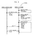
- Figure 3 illustrates a state transition diagram for the transmit finite state machine (TXFSM) of a multi-frame mode station.
- the two states shown are state 0-REPEAT MODE and state 1-TX FRAME.
- This figure, and subsequent figures depicting finite state machine representations, use the same finite state machine notation contained in the IEEE project 802 local networks standard.
- States are shown as vertical lines. Transitions are shown as horizontal lines with a number used to indicate the transition and an arrow indicating the transition direction. The inputs or conditions causing the transition are shown above the transition line; outputs or actions are shown below the transition line.
- the only transition while in REPEAT MODE state is transition 01 to state 1, the TX FRAME state.
- This transition occurs when the station has a frame ready to transmit (FR_REDY) and it acquires a usable token (U_TOK).
- the actions taken on the transition are to set the transmit flag (TX_F) and the frame counter (FC) to one.
- the station transmits the start frame sequence (SFS).
- the SFS is also referred to as the frame header.
- the SFS consists of the start delimiter (SD), the access control (AC) field, the frame control field, the destination address (DA), and the source address (SA).
- the end frame sequence (EFS) to be referred to subsequently, consists of the cyclic redundancy code (CRC), the ending delimiter (ED), and the frame status (FS) byte.
- Transition 11 occurs at the end of transmission of the start frame sequence.
- the TXFSM exits from state 1 and returns to the same state. This transition signals the transmitter to capture the source address from the transmitted frame and store it in the source address register while the frame information field is transmitted.
- Transitions 12 and 13 are exits from and back to state 1 which serve as time markers to set the I-bit in the ending delimiter.
- Transition 12 occurs when the transmission reaches the last byte (EOF) of the information field of an intermediate frame.
- EFS end frame sequence
- ED_F ending delimiter flag
- FC frame counter
- transition 14 the TXFSM exits from state 1 and returns to the repeat mode (state 0) when the multi-frame stripping finite state machine (STRIPFSM) to be discussed below, sets the end strip flag (ES_F) to 1 indicating that the frame stripping process has been completed. No action is needed on the transition.
- Transition 15 also causes a transition from state 1 (TX FRAME) back to state 0 (REPEAT MODE). The transition occurs when the station detects a corrupted token (C_TOK) or a hardware error (HW_ERR).
- C_TOK corrupted token
- HW_ERR hardware error
- FIGS 4A-C illustrate normal multi-frame stripping scenarios based on a large, medium and small ring respectively.
- the basic assumption made in the scenarios is that the ring is noise and error free (i.e., no data corruptions).
- three frames designated FA1, FA2 and FA3 are placed on the ring by a source station.
- the transmit frame flag (TX_F) is set to 1 at the first starting delimiter in the transmit sequence, and reset to 0 at the last ending delimiter.
- the TX_F indicates to the strip finite state machine (STRIPFSM) that the transmit operation is on when it is set to 1.
- STRIPFSM strip finite state machine
- the end delimiter flag (ED_F) is set to 1 at the starting delimiter of frame FA1 and reset to 0 at the ending delimiter of frame FA1. Setting the ED_F to 1 indicates to the STRIPFSM that the first ending delimiter of the multiple frame transmit sequence has not been sent yet. In other words, if the source station receives any ending delimiter while the flag is set to 1, it should be ignored since it did not originate at that station.
- a time trace of the changes in the frame counter is also shown in the figure.
- the station is operating in repeat mode and has not yet started to transmit.
- the station acquires a usable token at time t1.
- the station's TXFSM exits the REPEAT MODE (state 0) and enters the TX FRAME state (state 1).
- the frame counter is set to 1.
- the transmit station finishes sending the ending delimiter of the first frame FA1 and starts to send the first bit of the inter-frame gap (IFG).
- the frame counter is incremented from 1 to 2.
- the transmit station finishes sending the ending delimiter of the second frame FA2 and starts to send the first bit of the next inter-frame gap.
- the frame counter is incremented from 2 to 3.
- the receiver of the source station receives the ending delimiter of the first return frame FA1 at time t4.
- the frame counter is decremented from 3 to 2 indicating that the receiver has just stripped the first returning frame.
- E_F end strip flag
- the sequence of events causing changes in the frame counter follows the same pattern shown in Figure 4A.
- the small ring scenario is depicted in Figure 4C.
- the trace of the changes in the frame counter is shown in the figure and is described as follows.
- the station is in REPEAT MODE, waiting to start the transmit process.
- the station acquires a usable token at time t1 and its TXFSM transitions from state 0 to state 1.
- the frame counter is set to 1.
- the transmit station finishes sending the ending delimiter of the first frame FA1 at time t2, and starts sending the first bit of the inter-frame gap.
- the frame counter is incremented from 1 to 2.
- the receiver of the source station receives the ending delimiter of the first return frame FA1 at time t3.
- the frame counter is decremented from 2 to 1 indicating that the first return frame has been stripped.
- the rationale for the procedure for incrementing and decrementing the frame counter is based on the operations in a short ring scenario.
- the frame counter is incremented at the first bit of the inter-frame gap (bit-0 time) to prevent it from being decremented by a station's receiver before it is first incremented in a short ring scenario. This is due to the fact that the IFG bit-0 time is only one byte after the ending delimiter of a frame is transmitted while the minimum ring latency is three bytes long.
- the transmit station after sending the ending delimiter of the second frame FA2 is just starting to send the first bit of the inter-frame gap.
- the frame counter is incremented from 1 to 2.
- the receiver of the source station receives the ending delimiter of the second return frame FA2 at time t5.
- the frame counter is decremented from 2 to 1 indicating that the station has stripped the second return frame.
- the receiver of the source station receives the ending delimiter of the third return frame FA3.
- the frame counter value of 1 combined with the I-bit value of 0 indicates that this is the last frame to be stripped.
- the STRIPFSM terminates the frame stripping process at the end of the return frame status byte.
- the multi-frame stripping protocol is characterized by a strip finite state machine (STRIPFSM) illustrated in Figure 5.
- the STRIPFSM is applicable to both single frame and multi-frame stripping.
- the STRIPFSM works in concert with another finite state machine, called the isolated ending delimiter finite state machine (IEDFSM), to handle the frame stripping process under different error conditions.
- IEDFSM isolated ending delimiter finite state machine
- the four states shown are state 0-REPEAT, state 1-WAIT SD, state 2-WAIT ED, and state 3-STRIP FS.
- transition 01 the only transition is transition 01 to state 1, where the STRIPFSM waits for a starting delimiter.
- TX_F transmit flag
- the actions taken are to set the ending delimiter flag (ED_F), and the isolated delimiter flag (IED_F) to 1, and to set the end strip flag (ES_F) to 0.
- ED_F ending delimiter flag
- IED_F isolated delimiter flag
- ES_F end strip flag
- Setting the ES_F to 0 indicates that frame stripping is in progress.
- the frame counter (FC) is set to one by the TXFSM.
- FC the meaning of flag values is given in Table 1.
- Transition 11 causes an exit from the WAIT SD state to the WAIT ED state when the source receiver detects the starting delimiter of any returning frame.
- the source address flag (SA_F) is initialized to 0 on this transition.
- transition 12 represents an exit from the WAIT SD state to the REPEAT state.
- the end strip flag is set to 1 indicating that frame stripping has terminated and the end return code (ER) is set to 1 indicating that the PTT timer has expired.
- Transition 13 is an exit from and return to state 1 which occurs when a frame stripping station detects an isolated ending delimiter while stripping an intermediate frame.
- the full set of conditions necessary for this transition to occur are that the isolated ending delimiter flag (IED_F) be set to 1 enabling IED detection, the ending delimiter flag (ED_F) be set to 0 implying that the first ending delimiter has been transmitted, the frame counter value is greater than 1, and an isolated ending delimiter is detected.
- An isolated ending delimiter is an ending delimiter that is not preceded by a corresponding starting delimiter. This transition can only occur during receipt of the first frame at the source station's receiver. The actions taken are to decrement the frame counter by 1 and to set the isolated ending delimiter flag (IED_F) to 0 to disable IED detection.
- transition 14 represents a transition from the WAIT SD state to the STRIP FS state.
- the additional necessary conditions for the transition are that the transmit frame flag (TX_F) be set to 0 indicating that the single frame has been sent, the value of the frame counter is 1, the isolated ending delimiter flag is set to 1 indicating that IED detection has been enabled, the I-bit is set to 0, and no code violation errors have occurred. No action is taken on the transition.
- a burst error (B_E) caused by noise or station insertions, or a signal loss (S_L) caused by data clocking errors causes an exit from and return to state 1.
- the action taken is to set the isolated ending delimiter flag to 0 to disable IED detection. This is to guard against noise being interpreted as being an ending delimiter.
- the source station receives an ending delimiter belonging to an intermediate frame and remains in state 2.
- the necessary conditions for this transition are the receipt of an ending delimiter without an immedi strictlyately preceding starting delimiter, with the ending delimiter flag set to 0 indicating that the first ending delimiter has been transmitted, and with the value of the frame counter greater than 1.
- the only action taken is to decrement the frame counter by 1.
- Transition 23 occurs when a starting delimiter is detected while in state 2. An ending delimiter must not immediately follow the starting delimiter. The action taken is to re-initialize the source address flag to 0. This transi tion is always followed by either transition 24 or transition 27 depending upon whether or not the source address of each received frame matches with the contents of the station's source address register. Transition 24 occurs when the source address from the received frame is the same as the contents of the station's source address register which is loaded by code. The action taken is to set the source address flag to 1 indicating a source address match.
- Transition 25 is the normal strip terminating condition that results in an exit from state 2 to state 3 when the ending delimiter of the last frame is detected.
- the full set of necessary conditions are that an ending delimiter is detected that is not immediately preceded by a starting delimiter, the I-bit is set to 0 and no code violation errors have occurred, the frame counter is at 1, the source address flag (SA_F) is set to 1, the transmit frame flag (TX_F) is set to 0 indicating the last frame has been sent, and the ending delimiter flag (ED_F) is set to 0 indicating that the first ending delimiter has been transmitted. No action is taken on the transition. This transition represents the normal termination when the last frame in a multi-frame sequence is stripped.
- Transition 26 occurs when the physical trailer timer (PTT) expires.
- the station exits state 2 of the STRIPFSM and enters state 0.
- the two actions taken are to set the end strip flag (ES_F) to 1 indicating that frame stripping is terminated, and to set the end return code (ER) to 1 indicating that the PTT expiration was the reason for the frame strip termination.
- transition 27 the frame stripping station has detected a source address mismatch in the received frame with the frame counter set at 1 and with no code violation errors occurring during the receipt of the SFS of the return frame. This implies that frame stripping has progressed into a frame from another station on the ring.
- the full set of necessary conditions for this transition from state 2 back to state 0 are that a frame source address has been received that does not match the contents of the station's source address register, that no code violation errors have been detected in the SFS of the frame, that the transmit frame flag has been set to 0 indicating that the last frame has been sent, and that the frame counter is at 1.
- the two actions on the transition are to set the end strip flag (ES_F) to 1 and to set the end return code (ER) to 2 indicating that the reason for strip termination was a strip abort situation.
- transition 31 causes an exit from state 3 back to state 0. This transition occurs at the end of the returning frame status byte and completes the normal strip process.
- the only actions taken are to set the end strip flag to 1 and the end return code to 0 indicating normal frame strip termination.
- the sequence starts with transition 01 when the transmitter starts transmitting a multiple frame sequence. After the entire transmit sequence, the STRIPFSM remains in state 1 waiting to strip returning frames. Once the starting delimiter of the first returning frame FA1 is received, the STRIPFSM exits from state 1 to state 2 through transition 11. When the source address of FA1 is compared, the STRIPFSM goes through transition 24 to set the source address flag SA_F. When the ending delimiter of FA1 is received, the STRIPFSM goes through transition 22 to decrement the frame counter. The STRIPFSM goes through transition 23 when the starting delimiter of the second returning frame FA2 is received to received to reset the SA_F for FA2.
- the STRIPFSM then goes through transitions 24 and 22 for FA2 in the same way as was done for FA1.
- the STRIPFSM goes through transitions 23 and 24 again.
- Receiving the ending delimiter of returning frame FA3 causes the STRIPFSM to go through transition 25 and enter state 3.
- the STRIPFSM stays in state 3 until the end of the frame status byte of FA3 is received at which time it exits on transition 31 and returns to state 0.
- the STRIPFSM sets the end strip flag (ES_F) to 1 signalling to the TXFSM that the stripping process has completed. This setting of the ES_F causes the TXFSM to return to repeat mode from transmit mode.
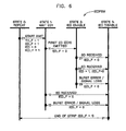
- a third finite state machine closely related to the TXFSM and the STRIPFSM is the isolated ending delimiter finite state machine (IEDFSM) shown in Figure 6.
- the IEDFSM manages the detection of the isolated ending delimiter and its function is integrated into the STRIPFSM.
- the IEDFSM has four states: state 0-REPEAT, state 1-WAIT ED1, state 2-IED ENABLE, and state 3-IED DISABLE.
- transition 01 transition 01 to state 1-WAIT ED1.
- the transition occurs when the TXFSM start transmitting the first frame.
- the actions taken are to set the isolated ending delimiter flag (IED_F) to 1 enabling IED detection and setting IED detect to zero.
- the transmit frame flag (TX_F) is set to 1 and the ending delimiter flag (ED_F) is set to 1 indicating that the first ending delimiter has not been transmitted.
- Transition 11 causes an exit to state 2, the IED ENABLE state when the TXFSM transmits the ending delimiter of the first frame.
- the action taken is to set the ending delimiter flag to 0 indicating that the first ending delimiter has been transmitted.
- Transition 12 to state 3 occurs when the source station receives a starting delimiter while waiting for the ending delimiter of the first frame.
- transition 13 to state 3 occurs when the source station detects a burst error or signal loss while in state 1.
- the action taken in both transitions 12 and 13 is to set the isolated ending delimiter flag to 0, thereby disabling IED detection.
- State 2 is the IED ENABLE state and three transitions can occur while in this state, all of which result in going to the IED DISABLE state (state 3).
- Transition 21 occurs when the source station receives a starting delimiter while in state 2. The only action taken is to set the isolated ending delimiter flag to 0.
- Transition 22 occurs when the source station receives an ending delimiter while in state 2 (the IED ENABLE state). The actions taken are to set the IED detect (IED) to 1 indicating that an isolated ending delimiter has been detected, and to set the isolated ending delimiter flag to 0 disabling further IED detection.
- Transition 23 occurs when a source station detects a burst error or signal loss while in state 2. The action taken is to set the isolated ending delimiter flag to 0 disabling IED detection.
- transition 31 causes the IEDFSM to exit from state 3, the IED DISABLE state, and return back to state 0 at the end of the frame stripping process.
- the condition triggering this transition is the end strip flag (ES_F) being set to 1 by the STRIPFSM. No action is taken on this transition.
- a stripping station can adapt to different strip error conditions and recover from the stripping process with a minimum loss of good data.
- three simple error scenarios are illustrated in Figures 7, 8 and 9.
- the scenario in Figure 7 depicts an error condition in which the starting delimiter of the first returning frame is corrupted.
- the sequence of transitions traced by the STRIPFSM is as follows:
- the stripping station is able to terminate its strip operation at the right time without damaging the frames of any other station.
- the sequence starts with transition 01 when the transmitter starts transmitting a multiple frame sequence.
- the STRIPFSM remains in state 1 waiting to strip returning frames.
- the STRIPFSM goes through transition 13 representing the detection of an isolated ending delimiter and remains in state 1.
- the STRIPFSM exits from state 1 to state 2 through transition 11. Comparing the source address of FA2 with the contents of the source address register causes transition 24 with the source address flag (SA_F) being set to 1.
- Receiving the ending delimiter frame of FA2 results in transition 22 with the frame counter being decremented.
- the STRIPFSM goes through transition 23 and resets the source address flag.
- the source address of FA3 is compared with the source address register resulting in transition 24 with the source address flag being set to 1.
- Receiving the ending delimiter of FA3 results in transition 25 with the STRIPFSM entering state 3.
- the STRIPFSM goes through transition 31 back to state 0.
- transition 01 starts with transition 01 followed by transition 11 to state 2 upon receiving the starting delimiter of the first returning frame FA1.
- the source address comparison is then made resulting in transition 24.
- transition 22 does not occur and thus the frame counter does not get decremented.
- the next two frames FA2 and FA3 are stripped with the STRIPFSM going through the usual transitions (23 - 24 - 22) for intermediate frames with the frame counter being decremented from 2 to 1 upon the receipt of the ending delimiter for FA3.
- the station will begin to strip the starting delimiter of FB1 from another station (transition 23). Since the source address of FB1 does not match the contents of the source address register, transition 27 occurs to stop the stripping immediately and return the STRIPFSM to the repeat state.
- the scenario shown in Figure 9 is for an error condition in which both the starting delimiter and ending delimiter of the first returning frame FA1 have been corrupted.
- the sequence of STRIPFSM transitions is as follows :
- the STRIPFSM starts with transition 01 to state 1, but then remains in state 1, stripping returning frame FA1 without any transition since both the starting delimiter and ending delimiter are corrupted.
- the STRIPFSM goes through the normal transitions for FA2 (11 - 24 - 22) which is regarded incorrectly as the first returning frame and for FA3 (23 - 24 - 22) which is regarded incorrectly as the second returning frame.
- the stripping station starts to strip frame FB1 from another station (transition 23) when the source address comparison detects a mismatch resulting in strip terminating transition 27 back to state 0.
- the stripping station terminates its stripping operation when it sees the source address of the first frame sent by another station.
- the stripping station overstrips one frame header.
- the other station sees its returning frame sequence exactly as in the scenario of Figure 7 so that it terminates stripping at the right time. Strip recovery again takes place in the second station.
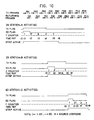
- Figure 10 illustrates an error condition in which both the ending delimiters of the first two returning frames FA1 and FA2 are corrupted either by ring error or by upstream overstripping. A chain reaction takes place leading to recovery from this error condition.
- the first stripping station (station A) in the ring overstrips two frames and leaves an isolated ending delimiter for the second stripping station.
- station A stops its stripping operation at the source address field of frame FB2 and it leaves the ending delimiter of FB2 as an isolated ending delimiter for station B to detect.
- the second stripping station (station B) in the ring overstrips one frame and leaves an isolated ending delimiter for the third stripping station.
- station B stops its stripping operation at the source address field of frame FC1, leaving the ending delimiter of FC1 as an isolated ending delimiter for station C to detect.
- the third stripping station (station C) in the ring stops its stripping operation at the normal time and the strip error condition is fully recovered.
- station C counts the isolated ending delimiter left by up-stream station B as its first stripped frame. It then continues its stripping process and finishes at the end of the frame status byte of frame FC3.
Landscapes
- Engineering & Computer Science (AREA)
- Computer Networks & Wireless Communication (AREA)
- Signal Processing (AREA)
- Small-Scale Networks (AREA)
Applications Claiming Priority (2)
| Application Number | Priority Date | Filing Date | Title |
|---|---|---|---|
| US422168 | 1989-10-16 | ||
| US07/422,168 US5142530A (en) | 1989-10-16 | 1989-10-16 | Multi-frame stripping protocol for token ring networks |
Publications (3)
| Publication Number | Publication Date |
|---|---|
| EP0424300A2 true EP0424300A2 (fr) | 1991-04-24 |
| EP0424300A3 EP0424300A3 (en) | 1991-08-07 |
| EP0424300B1 EP0424300B1 (fr) | 1995-02-22 |
Family
ID=23673678
Family Applications (1)
| Application Number | Title | Priority Date | Filing Date |
|---|---|---|---|
| EP90480135A Expired - Lifetime EP0424300B1 (fr) | 1989-10-16 | 1990-09-04 | Procédé d'élimination de trames multiples dans des réseaux en anneau à jeton |
Country Status (4)
| Country | Link |
|---|---|
| US (1) | US5142530A (fr) |
| EP (1) | EP0424300B1 (fr) |
| JP (1) | JPH0714161B2 (fr) |
| DE (1) | DE69017141T2 (fr) |
Cited By (1)
| Publication number | Priority date | Publication date | Assignee | Title |
|---|---|---|---|---|
| CN110996318A (zh) * | 2019-12-23 | 2020-04-10 | 广西电网有限责任公司电力科学研究院 | 一种变电站智能巡检机器人安全通信接入系统 |
Families Citing this family (11)
| Publication number | Priority date | Publication date | Assignee | Title |
|---|---|---|---|---|
| AU622208B2 (en) * | 1988-08-12 | 1992-04-02 | Digital Equipment Corporation | Frame removal mechanism for token ring networks |
| US5257264A (en) * | 1989-08-29 | 1993-10-26 | Digital Equipment Corporation | Automatically deactivated no-owner frame removal mechanism for token ring networks |
| US5280478A (en) * | 1989-08-29 | 1994-01-18 | Digital Equipment Corporation | No-owner frame and multiple token removal mechanism for token ring networks |
| US5327534A (en) * | 1990-07-30 | 1994-07-05 | Digital Equipment Corporation | Detection of duplicate alias addresses |
| US5216670A (en) * | 1991-07-03 | 1993-06-01 | International Business Machines Corporation | Message stripping protocol for a communication network |
| KR970002707B1 (ko) * | 1992-08-31 | 1997-03-08 | 엘지정보통신 주식회사 | 에프디디아이(fddi)브리지 시스템에서 프레임 스트리핑 방법 및 회로 |
| US5586266A (en) * | 1993-10-15 | 1996-12-17 | International Business Machines Corporation | System and method for adaptive, active monitoring of a serial data stream having a characteristic pattern |
| US5434978A (en) * | 1994-02-18 | 1995-07-18 | International Business Machines Corporation | Communications interface employing unique tags which enable a destination to decode a received message structure |
| GB2357658B (en) * | 1999-12-23 | 2002-09-25 | 3Com Corp | Stackable network unit including burst trasmission of packets |
| US7085970B2 (en) | 2002-07-23 | 2006-08-01 | International Business Machines Corporation | Fast detection of incorrect sampling in an oversampling clock and data recovery system |
| US8504687B2 (en) * | 2008-11-26 | 2013-08-06 | Telecom Italia S.P.A. | Application data flow management in an IP network |
Family Cites Families (9)
| Publication number | Priority date | Publication date | Assignee | Title |
|---|---|---|---|---|
| JPS58205353A (ja) * | 1982-05-25 | 1983-11-30 | Sharp Corp | デ−タ伝送システム |
| AU591645B2 (en) * | 1984-12-03 | 1989-12-14 | John Leslie Hullett | Queueing protocol |
| DE3507582A1 (de) * | 1985-03-04 | 1986-09-04 | Siemens AG, 1000 Berlin und 8000 München | Telekommunikationssystem mit einer mehrzahl von auf ein uebertragungsmedium mit ringstruktur zugreifenden teilnehmerstationen |
| FR2606239A1 (fr) * | 1986-10-30 | 1988-05-06 | Bull Sa | Procede et dispositif de transmission de donnees numeriques |
| JPH0666806B2 (ja) * | 1988-02-08 | 1994-08-24 | 住友電気工業株式会社 | トークンリング伝送方式 |
| AU622208B2 (en) * | 1988-08-12 | 1992-04-02 | Digital Equipment Corporation | Frame removal mechanism for token ring networks |
| US4932023A (en) * | 1989-06-20 | 1990-06-05 | International Business Machines Corporation | Frame stripping protocol for early token release in a ring communication network |
| US4932032A (en) * | 1989-08-03 | 1990-06-05 | At&T Bell Laboratories | Tapered semiconductor waveguides |
| US4964113A (en) * | 1989-10-20 | 1990-10-16 | International Business Machines Corporation | Multi-frame transmission control for token ring networks |
-
1989
- 1989-10-16 US US07/422,168 patent/US5142530A/en not_active Expired - Fee Related
-
1990
- 1990-09-04 EP EP90480135A patent/EP0424300B1/fr not_active Expired - Lifetime
- 1990-09-04 DE DE69017141T patent/DE69017141T2/de not_active Expired - Fee Related
- 1990-10-02 JP JP2263252A patent/JPH0714161B2/ja not_active Expired - Lifetime
Cited By (2)
| Publication number | Priority date | Publication date | Assignee | Title |
|---|---|---|---|---|
| CN110996318A (zh) * | 2019-12-23 | 2020-04-10 | 广西电网有限责任公司电力科学研究院 | 一种变电站智能巡检机器人安全通信接入系统 |
| CN110996318B (zh) * | 2019-12-23 | 2021-07-23 | 广西电网有限责任公司电力科学研究院 | 一种变电站智能巡检机器人安全通信接入系统 |
Also Published As
| Publication number | Publication date |
|---|---|
| US5142530A (en) | 1992-08-25 |
| JPH03140038A (ja) | 1991-06-14 |
| DE69017141D1 (de) | 1995-03-30 |
| EP0424300B1 (fr) | 1995-02-22 |
| EP0424300A3 (en) | 1991-08-07 |
| JPH0714161B2 (ja) | 1995-02-15 |
| DE69017141T2 (de) | 1995-08-10 |
Similar Documents
| Publication | Publication Date | Title |
|---|---|---|
| US4566097A (en) | Token ring with secondary transmit opportunities | |
| EP0146831B1 (fr) | Protocole de dépouillement de message pour réseau de communication en anneau | |
| US4726018A (en) | Method of providing priority access to a transmission communication ring | |
| US4513370A (en) | Data transfer control system and method for a plurality of linked stations | |
| EP0424300B1 (fr) | Procédé d'élimination de trames multiples dans des réseaux en anneau à jeton | |
| US4566098A (en) | Control mechanism for a ring communication system | |
| EP0404707B1 (fr) | Méthode de dépouillement de trames pour extraire des messages entachés d'erreurs dans un réseau de communication en anneau | |
| JPH0127615B2 (fr) | ||
| EP0372765A2 (fr) | Méthode et appareil pour réaliser des opérations à jeton restreintes sur un réseau FDDI | |
| US5185863A (en) | Byte-wide elasticity buffer | |
| EP0424302A2 (fr) | Méthode pour le contrôle des transmissions à trame multiple dans les réseaux à jeton | |
| US5051986A (en) | Asynchronous priority select logic | |
| US4975907A (en) | Method and device for the asynchronous transmission of data by packets | |
| JP2648752B2 (ja) | データ情報の正確なデコードを保証する装置 | |
| JPH05252165A (ja) | 衛星通信制御装置 | |
| US4751700A (en) | Method and apparatus for local area communication networks | |
| EP0597030B1 (fr) | Mecanisme d'enlevement de trame sans proprietaire automatiquement mis hors fonction, pour des reseaux en anneau a jeton | |
| CA1204189A (fr) | Mecanisme de controle pour systeme de communication annulaire | |
| EP0479607B1 (fr) | Méthode et appareil de détection d'une séquence au bits de trame dans un système numérique de transmission de données | |
| EP0719011A2 (fr) | Mécanisme extracteur de trames dans un réseau en anneau à jeton | |
| JPH05252085A (ja) | 衛星通信制御装置 | |
| JPS5828979B2 (ja) | デ−タフレ−ム伝送方式 | |
| US20090276652A1 (en) | Method of Link Word Synchronization | |
| JPS61172454A (ja) | 環状網の伝送方式 | |
| JPH0131735B2 (fr) |
Legal Events
| Date | Code | Title | Description |
|---|---|---|---|
| PUAI | Public reference made under article 153(3) epc to a published international application that has entered the european phase |
Free format text: ORIGINAL CODE: 0009012 |
|
| 17P | Request for examination filed |
Effective date: 19901213 |
|
| AK | Designated contracting states |
Kind code of ref document: A2 Designated state(s): DE FR GB |
|
| PUAL | Search report despatched |
Free format text: ORIGINAL CODE: 0009013 |
|
| AK | Designated contracting states |
Kind code of ref document: A3 Designated state(s): DE FR GB |
|
| 17Q | First examination report despatched |
Effective date: 19930618 |
|
| GRAA | (expected) grant |
Free format text: ORIGINAL CODE: 0009210 |
|
| AK | Designated contracting states |
Kind code of ref document: B1 Designated state(s): DE FR GB |
|
| REF | Corresponds to: |
Ref document number: 69017141 Country of ref document: DE Date of ref document: 19950330 |
|
| ET | Fr: translation filed | ||
| PLBE | No opposition filed within time limit |
Free format text: ORIGINAL CODE: 0009261 |
|
| STAA | Information on the status of an ep patent application or granted ep patent |
Free format text: STATUS: NO OPPOSITION FILED WITHIN TIME LIMIT |
|
| 26N | No opposition filed | ||
| PGFP | Annual fee paid to national office [announced via postgrant information from national office to epo] |
Ref country code: FR Payment date: 19990917 Year of fee payment: 10 |
|
| PG25 | Lapsed in a contracting state [announced via postgrant information from national office to epo] |
Ref country code: FR Free format text: LAPSE BECAUSE OF NON-PAYMENT OF DUE FEES Effective date: 20010531 |
|
| REG | Reference to a national code |
Ref country code: FR Ref legal event code: ST |
|
| PGFP | Annual fee paid to national office [announced via postgrant information from national office to epo] |
Ref country code: GB Payment date: 20010903 Year of fee payment: 12 |
|
| REG | Reference to a national code |
Ref country code: GB Ref legal event code: IF02 |
|
| PG25 | Lapsed in a contracting state [announced via postgrant information from national office to epo] |
Ref country code: GB Free format text: LAPSE BECAUSE OF NON-PAYMENT OF DUE FEES Effective date: 20020904 |
|
| PGFP | Annual fee paid to national office [announced via postgrant information from national office to epo] |
Ref country code: DE Payment date: 20021002 Year of fee payment: 13 |
|
| GBPC | Gb: european patent ceased through non-payment of renewal fee |
Effective date: 20020904 |
|
| PG25 | Lapsed in a contracting state [announced via postgrant information from national office to epo] |
Ref country code: DE Free format text: LAPSE BECAUSE OF NON-PAYMENT OF DUE FEES Effective date: 20040401 |