EP0424358A2 - Heizgerät mit einer Vorrichtung zur Steuerung des Durchsatzes der Verbrennungsluft - Google Patents
Heizgerät mit einer Vorrichtung zur Steuerung des Durchsatzes der Verbrennungsluft Download PDFInfo
- Publication number
- EP0424358A2 EP0424358A2 EP90890286A EP90890286A EP0424358A2 EP 0424358 A2 EP0424358 A2 EP 0424358A2 EP 90890286 A EP90890286 A EP 90890286A EP 90890286 A EP90890286 A EP 90890286A EP 0424358 A2 EP0424358 A2 EP 0424358A2
- Authority
- EP
- European Patent Office
- Prior art keywords
- combustion air
- valve
- burner
- channel
- duct
- Prior art date
- Legal status (The legal status is an assumption and is not a legal conclusion. Google has not performed a legal analysis and makes no representation as to the accuracy of the status listed.)
- Granted
Links
Images

Classifications
-
- F—MECHANICAL ENGINEERING; LIGHTING; HEATING; WEAPONS; BLASTING
- F23—COMBUSTION APPARATUS; COMBUSTION PROCESSES
- F23C—METHODS OR APPARATUS FOR COMBUSTION USING FLUID FUEL OR SOLID FUEL SUSPENDED IN A CARRIER GAS OR AIR
- F23C7/00—Combustion apparatus characterised by arrangements for air supply
- F23C7/008—Flow control devices
-
- F—MECHANICAL ENGINEERING; LIGHTING; HEATING; WEAPONS; BLASTING
- F23—COMBUSTION APPARATUS; COMBUSTION PROCESSES
- F23N—REGULATING OR CONTROLLING COMBUSTION
- F23N3/00—Regulating air supply or draught
-
- F—MECHANICAL ENGINEERING; LIGHTING; HEATING; WEAPONS; BLASTING
- F23—COMBUSTION APPARATUS; COMBUSTION PROCESSES
- F23N—REGULATING OR CONTROLLING COMBUSTION
- F23N2235/00—Valves, nozzles or pumps
- F23N2235/02—Air or combustion gas valves or dampers
- F23N2235/06—Air or combustion gas valves or dampers at the air intake
Definitions
- the invention relates to a device for controlling the throughput of the combustion air to a forced air burner of a heating device, for example a water heater, fed with a fuel-air mixture.
- the object of the invention is to enable a device of the type mentioned, a manual or automatic depending on the control equipment of the heater to the given local conditions of the combustion air and exhaust gas routing or to correct the setting of the combustion air device so that the output and air ratio again corresponds to the design data.
- cooling of the combustion air in phases is to prevent cooling, in particular in a mode independent of ambient air; Such an operating mode can possibly result in the heat exchanger freezing.
- this object is initially achieved by controlling the throughput of the combustion air in the combustion air duct is automatically provided during breaks in operation, for example under the influence of a return spring, and a valve that opens and only opens when there is a demand for heat, which can restrict or block the circulation of the combustion air as required, or only release this circulation as required.
- an electrically actuable solenoid valve that opens when the power is supplied is suitable for reliable control.
- valve acts as a circulation lock, which means that the coil is only energized when the device requires heat and the throttle plug is raised against the preset mechanical stroke limit.
- combustion air can be supplied to the blower through the inlet in a targeted and metered manner only while the burner is in operation, taking into account a safety-related pre-run and post-run time.
- the fan starts up and generates a negative pressure which is detected by a pressure switch integrated in the device and which energizes the solenoid coil and opens the throttle when the switching value is reached .
- the switching value in this device system takes into account the tolerance range of the possible leak rate.
- a device which controls the solenoid valve or a linear stepper motor and which, depending on the prevailing differential pressure via the combustion air duct and the housing via a differential pressure switch, starts the burner release at a pressure determined in tests if the short-term operation of the Fan the value specified for the tightness control comes up.
- the burner operation is switched off, and taking into account a run-on time for the fan, the same becomes current coil switched off.
- the throttle cone is pressed onto the sealing seat due to the spring force and its own weight and thus closes the combustion air duct in the device and thus prevents circulation and cooling.
- the pressure drop across the throttle point can be specified as the target value for a gas pressure regulator with pneumatic mixture control.
- the burner could be operated modulating in terms of its technical suitability.
- One advantage, particularly with fan-type burners, is the use of such a gas pressure regulator, which keeps the air ratio constant in the set range by adapting the gas flow by means of a pneumatic connection to the combustion air device in response to changes in starting and changing operations sentence.
- heating and condensing boilers with fan burner are often prone to lockouts (due to insufficient ionization current) if they are equipped with a fixed allocation of the combustion air and gas throttle through operationally defined cross sections.
- a stepper motor and a hydraulic linear motor are also conceivable as drives for the circulation block, the actuating movement of the motor being triggered by the differential pressure generated on the heating water side during operation of the intermittent circulation pump.
- valve The adjustment of the valve is made possible in the simplest way by the fact that the force of the return spring can be adjusted as required.
- the force of the return spring can be adjusted as required, and the pressure thus generated via the throttle point Pneumatic control of a gas / air ratio pressure regulator is used, which compensates for operational fluctuations after a one-time adjustment and adjustment in the factory by keeping the air ratio constant by changing the gas volume flow.
- valve body of the valve arranged in the combustion air duct within a duct belonging to this duct, above the combustion chamber, the heat exchanger and the exhaust hood of the forced draft burner, serves as a valve seat and is provided in the wall of this duct Recess coaxially opposite, through which the combustion air flows to the forced air burner.
- Such a channel can be penetrated by the exhaust gas duct, which extends to the exhaust hood of the combustion chamber of the device, and a sleeve surrounding this exhaust duct can thus form the inlet for the combustion air. Furthermore, the channel between the inlet for the combustion air and the recess forming the outlet for the combustion air can very conveniently receive a dust filter which can be monitored well by the pressure difference monitor located nearby.
- the channel can run on the underside of the ceiling of a housing that tightly encloses the device, so that this ceiling advantageously embodies a wall of this channel and on this ceiling both the sleeve that forms the inlet of the combustion air and the exhaust gas duct and the base of the combustion air flow rate Valves can be attached.
- the heat exchanger 3 of a device for example a water heater, which is heated by a forced draft burner 1 and is arranged above a combustion chamber 2, is located within a technically sealed housing 21, the ceiling of which is designated by 4.
- This housing cover 4 is penetrated within a sleeve 5 by an exhaust gas duct 7 adjoining the exhaust gas hood 6 of the heat exchanger 3, which exhaust gas duct 7 is held in a sealing manner in the exhaust gas connector 8 of the exhaust gas hood 6 by means of a seal 9.
- This seal 9 seals the exhaust duct 7 also against the wall of a duct carrying the combustion air 10, which runs in the upper part of the device housing below the ceiling 4 and is fed via the sleeve 5 with combustion air from the installation room of the device or an external wall connection.
- the combustion air from this duct 10 is fed to the forced draft burner 1 by means of a blower (not shown) via the mixture distribution chamber 11 and the connection 12.
- the combustion air (room air or fresh air) emerges from the duct 10 via the recess 13 of the wall of this duct 10, which can be closed in phases by means of a conical valve body 14 coaxial with this recess 13.
- the combustion air entering the device housing via this recess 13 reaches the mixture distribution chamber 11 via the blower, but is previously cleaned in the dust filter 15 which has been eroded between the sleeve 5 and the recess 13
- a differential pressure monitor 16 is arranged in the area of the channel 10, which monitors the compliance with the pressure conditions required for the correct operation of the device.
- a direct-current magnet 18 is used according to FIG.
- the respective end position or the operating state can be recognized and controlled by any monitoring element, for example by a microswitch.
- a differential pressure switch (FIGS. 1, 16) can only excite the DC coil 18 when the blower reaches a certain negative pressure, but this always depends on the operating state of the device.
- the conical valve body 14 is pressed by its return spring 17 onto the valve seat 13 formed by the recess 13, closes or (continuously) throttles the combustion air throughput
- Burner 1 and thereby acts as a circulation lock or throttle.
- the direct current magnet 18 is excited and pulls the spring 17 against the stop 20 that can be adjusted from the outside.
- This adjustability enables the device to be subsequently adjusted at the installation location.
- the return spring 17 and / or the direct current magnet 18 By selecting the return spring 17 and / or the direct current magnet 18, a different dimensioning of the combustion air throughput for heating or hot water operation is also possible.
Landscapes
- Engineering & Computer Science (AREA)
- Chemical & Material Sciences (AREA)
- Combustion & Propulsion (AREA)
- Mechanical Engineering (AREA)
- General Engineering & Computer Science (AREA)
- Regulation And Control Of Combustion (AREA)
- Air Supply (AREA)
- Air-Conditioning For Vehicles (AREA)
- Direct Air Heating By Heater Or Combustion Gas (AREA)
Abstract
Description
- Die Erfindung betrifft eine Vorrichtung zur Steuerung des Durchsatzes der Verbrennungsluft zu einem mit einem Brennstoff-Luft-Gemisch gespeisten Gebläsebrenner eines Heizgerätes, zum Beispiel eines Wasserheizers.
- Wenn solche Geräte eine Bauart aufweisen, die sie befähigt, sowohl raumluftabhängig als auch raumluftunabhängig betrieben zu werden und sowohl für einen Anschluß an einen Kamin als auch für einen unmittelbaren Anschluß an eine Außenwandöffnung geeignet zu sein, bedeutet dies eine große Breite der Druckverluste sowohl auf der Abgas- als auch auf der Verbrennungsluftseite. Bei diesen Bandbreiten ist es kaum möglich, einen optimalen Betrieb des Gerätes hinsichtlich Wirkungsgrad und Emissionswerte zu gewährleisten. Eine Möglichkeit wäre die selbsttätige Anpassung zum Beispiel mittels einer im Abgasstrom angeordneten Lambda-Sonde, die die Abweichung von einem vorgegebenen Soll-Wert erfaßt und zum Beispiel über eine Drehzahlregelung die Drehzahl des Gebläsemotors beziehungsweise mit Spannungsänderung auf eine Gleichstromspule einer Verbrennungsluft-Zirkulationssperre reagiert und entsprechende Korrekturen vornimmt.
- Aufgabe der Erfindung ist es, bei einer Vorrichtung der eingangs bezeichneten Gattung eine manuelle oder automatische je nach regelungstechnischer Ausrüstung des Heizgerätes an die jeweils vorgegebenen örtlichen Verhältnisse der Verbrennungsluft und Abgasführung zu ermöglichen beziehungsweise die Einstellung der Verbrennungslufteinrichtung so zu korrigieren, daß die abgegebene Leistung und Luftzahl den Auslegungsdaten wieder entspricht.
- Ferner soll durch eine phasenweise Zirkulationssperre der Verbrennungsluft einer Auskühlung, insbesondere bei einer raumluftunabhängigen Betriebsweise, vorgebeugt werden; eine solche Betriebsweise kann gegebenenfalls ein Einfrieren des Wärmetauschers zur Folge haben.
- Diese Aufgabe wird erfindungsgemäß zunächst dadurch gelöst, daß zur Steuerung des Durchsatzes der Verbrennungs luft in der Verbrennungsluftführung ein in Betriebspausen selbsttätig, zum Beispiel unter dem Einfluß einer Rückhohlfeder, schließendes und nur bei einer Wärmeanforderung öffnendes Ventil vorgesehen ist, das die Zirkulation der Verbrennungsluft bedarfsweise zu drosseln oder zu sperren vermag, beziehungsweise diese Zirkulation nur bedarfsweise freigibt.
- Nach einer bevorzugten Ausführungsform der erfindungsgemäßen Vorrichtung eignet sich für eine zuverlässige Steuerung ein elektrisch betätigbares, bei Stromzufuhr öffnendes Magnetventil.
- Eine einstellbare Justierung dieses Ventiles ermöglicht es, den Verbrennungsluftdurchsatz vor Ort den jeweiligen Verhältnissen entsprechend zu steuern. Das Ventil wirkt als Zirkulationssperre, das heißt, daß nur bei Wärmeanforderung an das Gerät die Spule erregt wird und der Drosselkegel gegen die voreingestellte mechanische Hubbegrenzung angehoben wird. Somit kann nur während des Betriebes des Brenners unter Berücksichtigung einer sicherheitstechnisch notwendigen Vor- und Nachlaufzeit dem Gebläse Verbrennungsluft durch den Einlaß gezielt und dosiert zugeführt werden.
- Als Variante ist denkbar, daß bei Geräten, die in Wohnräumen aufgestellt werden, zur Verbesserung der Betriebssicherheit bei Wärmeanforderung das Gebläse anläuft und einen Unterdruck erzeugt, der über einen im Gerät integrierten Druckwächter erfaßt wird und bei Erreichen des Schaltwertes die Magnetspule erregt und die Drossel öffnet. Der Schaltwert bei diesem Gerätesystem berücksichtigt den Toleranzbereich der möglichen Leckrate.
- In Ausgestaltung der Erfindung ist eine das Magnetventil oder einen Linearschrittmotor steuernde Einrichtung vorgesehen, die abhängig von herrschendem Differenzdruck über die Verbrennungsluftführung und das Gehäuse über einen Differenzdruckwächter bei einem in Versuchen festgelegten Druck die Brennerfreigabe startet, wenn sich in einer bestimmten Zeit bei einem kurzfristigen Betrieb des Gebläses der für die Dichtheitskontrolle festgelegte Wert aufkommt.
- Als weitere Sicherheit ist die Endlagenmeldung des Drosselkegels des Magnetventils durch einen Mikroschalter denkbar.
- Bei Erreichen der voreingestellten Soll-Temperatur wird der Brennerbetrieb ausgeschaltet, und unter Berücksichtigung einer Nachlaufzeit für das Gebläse wird die Gleich stromspule stromlos geschaltet. Der Drosselkegel wird aufgrund der Federkraft und des Eigengewichts auf den Dichtsitz gepreßt und verschließt somit die Verbrennungsluftführung in das Gerät und verhindert so eine Zirkulation sowie die Auskühlung.
- Weitere Varianten der Betriebsweise der Zirkulationssperre sind möglich. Bei entsprechender Auslegung der Gleichstromspule und der mechanischen Hubbegrenzung ist ein zweistufiger oder mehrstufiger Betrieb des Brenners denkbar, denn für jede angelegte Spannung und festgelegte Federkraft ist eine Zuordnung je Leistungsstufe unter Berücksichtigung der gewünschten Luftzahl möglich. Der jeweils notwendige Öffnungsquerschnitt pro Leistungsstufe wurde vorher zugeordnet.
- Des weiteren kann der Druckabfall über die Drosselstelle als Soll-Wert für einen Gasdruckregler mit pneumatischer Gemischregelung vorgegeben werden. Hier könnte der Brenner im Bereich seiner technischen Tauglichkeit modulierend betrieben werden. Ein Vorteil, besonders bei Gebläseflächenbrennern, ist der Einsatz eines solchen Gasdruckreglers, der durch pneumatische Anbindung an die Verbrennungslufteinrichtung auf Veränderungen bei Start- und Wechselbetriebsvorgängen die Luftzahl im eingestellten Bereich konstant hält durch Anpassung des Gasdurch satzes. Hier neigen Heiz- und Brennwertgeräte mit Gebläseflächenbrenner häufig zu Störabschaltungen (durch einen zu geringen Ionisationsstrom), wenn sie mit einer festen Zuordnung der Verbrennungsluft und Gasdrossel durch betriebsmäßig festgelegte Querschnitte ausgerüstet sind.
- Die bei solchen Vorgängen schwankenden Luftzahlen bewirken ein Abheben der Flammen von der Brennerplatte und damit bedingt einen geringeren Ionisationsstrom, der so weit absinkt, daß es zu einer Störabschaltung kommen kann. Die pneumatische Gemischregelung würde bei solchen Vorgängen die Luftzahl in einem kleinen Bereich konstant halten und somit die Abhebeneigung der Flammen von der Brennerplatte reduzieren.
- Als Antrieb für die Zirkulationssperre ist auch ein Schrittmotor sowie ein hydraulischer Linearmotor denkbar, wobei die Stellbewegung des Motors durch den erzeugten Differenzdruck auf der Heizwasserseite während des Betriebes der intermittierenden Umwälzpumpe ausgelöst wird.
- Die Einstellung des Ventiles wird auf einfachste Weise dadurch ermöglicht, daß die Kraft der Rückholfeder bedarfsweise einstellbar ist.
- Die Kraft der Rückholfeder ist bedarfsweise einstellbar, und der so über die Drosselstelle entstehende Druck zur pneumatischen Ansteuerung eines Verhältnisdruckreglers Gas/Luft wird genutzt, der nach werkseitiger einmaliger Justierung und Abstimmung betriebsmäßige Schwankungen ausgleicht, indem durch Änderung des Gasvolumenstroms die Luftzahl konstant gehalten wird.
- In baulicher Hinsicht ist es besonders günstig und raumsparend, wenn der Ventilkörper des in der Verbrennungsluftführung angeordneten Ventiles innerhalb eines zu dieser Führung gehörenden, oberhalb der Brennkammer, des Wärmetauschers und der Abgashaube des Gebläsebrenners angeordneten Kanales einer in der Wandung dieses Kanales vorgesehene, als Ventilsitz dienenden Ausnehmung koaxial gegenüberliegt, über die die Verbrennungsluft dem Gebläsebrenner zuströmt.
- Ein solcher Kanal kann von der Abgasführung, die an die Abgashaube der Brennkammer des Gerätes ausgeht, durchsetzt werden und eine diese Abgasführung umschließende Manschette kann solcherart den Einlaß für die Verbrennungsluft bilden. Ferner kann der Kanal zwischen dem Einlaß für die Verbrennungsluft und der den Auslaß für die Verbrennungsluft bildenden Ausnehmung sehr günstig einen Staubfilter aufnehmen, der von dem in der Nähe untergebrachten Druckdifferenzwächter gut überwacht werden kann.
- Der Kanal kann an der Unterseite der Decke eines das Gerät dicht umschließenden Gehäuses verlaufen, so daß diese Decke vorteilhafterweise eine Wandung dieses Kanales verkörpert und an dieser Decke sowohl die den Einlaß der Verbrennungsluft bildende und die Abgasführung umschließende Manschette als auch die Basis des den Verbrennungsluftdurchsatz steuernden Ventiles befestigt werden kann.
- Ein Ausführungsbeispiel des Erfindungsgegenstandes ist in den Zeichnungen veranschaulicht und nachstehend anhand dieser Zeichnungen erläutert.
- Im einzelnen zeigen:
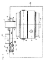
- Figur 1 das Gerät mit der Vorrichtung in einem schematischen Vertikalschnitt,
- Figur 2 a einen Schnitt durch das zugehörige Ventil in Betriebsstellung und
- Figur 2 b einen Schnitt durch das zugehörige Ventil in Ruhestellung.
- Der mit einem Gebläsebrenner 1 beheizte, oberhalb eines Brennraumes 2 angeordnete Wärmetauscher 3 eines Gerätes, zum Beispiel eines Wasserheizers, befindet sich innerhalb eines technisch dichten Gehäuses 21, dessen Decke mit 4 bezeichnet ist.
- Diese Gehäusedecke 4 wird innerhalb einer Manschette 5 von einer an die Abgashaube 6 des Wärmetauschers 3 anschließenden Abgasführung 7 durchsetzt, die im Abgasstutzen 8 der Abgashaube 6 mittels einer Dichtung 9 dichtend gehalten wird.
- Diese Dichtung 9 dichtet die Abgasführung 7 auch gegen die Wandung eines die Verbrennungsluft führenden Kanales 10 ab, der im oberen Teil des Gerätegehäuses unterhalb dessen Decke 4 verläuft und über die Manschette 5 mit Verbrennungsluft aus dem Aufstellungsraum des Gerätes oder einem Außenmaueranschluß gespeist wird. Dem Gebläsebrenner 1 wird die Verbrennungsluft aus diesem Kanal 10 mittels eines nicht dargestellten Gebläses über die Gemischverteilerkammer 11 und den Anschluß 12 zugeführt. Der Austritt der Verbrennungsluft (Raumluft oder Frischluft) aus dem Kanal 10 erfolgt über die Ausnehmung 13 der Wandung dieses Kanales 10, die mittels eines zu dieser Ausnehmung 13 koaxialen kegelförmigen Ventilkörpers 14 phasenweise verschließbar ist. Die über diese Ausnehmung 13 in das Gerätegehäuse eintretende Verbrennungsluft gelangt über das Gebläse in die Gemischverteilerkammer 11, wird jedoch vorher in dem zwischen der Manschette 5 und der Ausnehmung 13 angerodneten Staubfilter 15 gereinigte
- Ferner ist im Bereich des Kanals 10 ein Differenzdruckwächter 16 angeordnet, der die Einhaltung der für den einwandfreien Betrieb des Gerätes erforderlichen Druckverhältnisse überwacht.
- Zur Steuerung des in bezug zur Ausnehmung 13 axial beweglich gelagerten Ventilkörpers 14 dient gemäß Figur 2 ein Gleichstrommagnet 18, der gegen die Wirkung der den Ventilkörper 14 beeinflussenden Rückholfeder 17 erregbar und mittels einer Basis 19 an der Gehäusedecke 4 befestigt ist.
- Die jeweilige Endlage beziehungsweise der Betriebszustand kann durch ein beliebiges Überwachungselement erkannt und gesteuert werden, zum Beispiel durch einen Mikroschalter. Ebenso kann ein Differenzdruckwächter (Figuren 1, 16) erst bei Erreichen eines bestimmten Unterdrucks durch das Gebläse die Gleichstromspule 18 erregen, dies aber stets in Abhängigkeit vom Betriebszustand des Gerätes.
- Die Funktion der Vorrichtung ergibt sich aus deren oben geschildertem Aufbau wie folgt:
- In Betriebspausen wird der kegelförmige Ventilkörper 14 von seiner Rückholfeder 17 auf den von der Ausnehmung 13 gebildeten Ventilsitz 13 gedrückt, verschließt oder (stufenlos) drosselt den Verbrennungsluftdurchsatz zum
- Brenner 1 und wirkt dadurch als Zirkulationssperre beziehungsweise -drossel.
- Bei allgemeiner Wärmeanforderung, sei es einer Heizungswasser- oder Brauchwasseranforderung, wird der Gleichstrommagnet 18 erregt und zieht die Feder 17 gegen den von außen einstellbaren Anschlag 20.
- Diese Einstellbarkeit ermöglicht eine nachträgliche Justierung der Vorrichtung am Einbauort. Durch Auswahl der Rückholfeder 17 und/oder des Gleichstrommagneten 18 ist auch eine unterschiedliche Bemessung des Verbrennungsluftdurchsatzes für Heizungs- oder Brauchwasserbetrieb möglich.
Claims (6)
Applications Claiming Priority (2)
| Application Number | Priority Date | Filing Date | Title |
|---|---|---|---|
| AT2410/89 | 1989-10-20 | ||
| AT0241089A AT393890B (de) | 1989-10-20 | 1989-10-20 | Vorrichtung zur steuerung des durchsatzes der verbrennungsluft zu einem geblaesebrenner |
Publications (3)
| Publication Number | Publication Date |
|---|---|
| EP0424358A2 true EP0424358A2 (de) | 1991-04-24 |
| EP0424358A3 EP0424358A3 (de) | 1991-06-05 |
| EP0424358B1 EP0424358B1 (de) | 1994-06-01 |
Family
ID=3533848
Family Applications (1)
| Application Number | Title | Priority Date | Filing Date |
|---|---|---|---|
| EP90890286A Expired - Lifetime EP0424358B1 (de) | 1989-10-20 | 1990-10-22 | Heizgerät mit einer Vorrichtung zur Steuerung des Durchsatzes der Verbrennungsluft |
Country Status (3)
| Country | Link |
|---|---|
| EP (1) | EP0424358B1 (de) |
| AT (2) | AT393890B (de) |
| DE (2) | DE9014470U1 (de) |
Cited By (5)
| Publication number | Priority date | Publication date | Assignee | Title |
|---|---|---|---|---|
| EP0429034B1 (de) * | 1989-11-24 | 1996-06-05 | Joh. Vaillant GmbH u. Co. | Verfahren zur Steuerung eines Heizgerätes |
| WO2000011411A3 (en) * | 1998-08-21 | 2000-06-22 | Srp 687 Pty Ltd | Water heater with heat sensitive air inlet |
| AT407434B (de) * | 1998-11-30 | 2001-03-26 | Vaillant Gmbh | Wärmetauscherdichtung |
| EP1363077A3 (de) * | 2002-05-14 | 2005-02-02 | Mitsubishi Heavy Industries, Ltd. | Brennkammer für eine Gasturbine und Verfahren zur Kontrolle der Verbrennung |
| US10247416B2 (en) | 2015-03-23 | 2019-04-02 | Honeywell Technologies Sarl | Method for operating a gas burner |
Family Cites Families (5)
| Publication number | Priority date | Publication date | Assignee | Title |
|---|---|---|---|---|
| GB886349A (en) * | 1958-11-14 | 1962-01-03 | Denis Wharmby Myers | Improvements in oil burner draught control devices |
| US4262608A (en) * | 1979-06-14 | 1981-04-21 | Jackson Bert W | Method and apparatus for powered flue products exhaust and preheated combustion air supply |
| EP0024376A1 (de) * | 1979-08-17 | 1981-03-04 | Archibald Watson Kidd | Heizapparat |
| NL8600247A (nl) * | 1986-01-31 | 1987-08-17 | Atag Bv Apparatenfab | Verwarmingsinrichting. |
| EP0303559A3 (de) * | 1987-08-13 | 1990-06-20 | Joh. Vaillant GmbH u. Co. | Verbrennungsluftführung zum Brenner eines brennerbeheizten Gerätes, z.B. eines Wasserheizers |
-
1989
- 1989-10-20 AT AT0241089A patent/AT393890B/de not_active IP Right Cessation
-
1990
- 1990-10-16 DE DE9014470U patent/DE9014470U1/de not_active Expired - Lifetime
- 1990-10-22 DE DE59005920T patent/DE59005920D1/de not_active Expired - Fee Related
- 1990-10-22 AT AT90890286T patent/ATE106527T1/de not_active IP Right Cessation
- 1990-10-22 EP EP90890286A patent/EP0424358B1/de not_active Expired - Lifetime
Cited By (5)
| Publication number | Priority date | Publication date | Assignee | Title |
|---|---|---|---|---|
| EP0429034B1 (de) * | 1989-11-24 | 1996-06-05 | Joh. Vaillant GmbH u. Co. | Verfahren zur Steuerung eines Heizgerätes |
| WO2000011411A3 (en) * | 1998-08-21 | 2000-06-22 | Srp 687 Pty Ltd | Water heater with heat sensitive air inlet |
| AT407434B (de) * | 1998-11-30 | 2001-03-26 | Vaillant Gmbh | Wärmetauscherdichtung |
| EP1363077A3 (de) * | 2002-05-14 | 2005-02-02 | Mitsubishi Heavy Industries, Ltd. | Brennkammer für eine Gasturbine und Verfahren zur Kontrolle der Verbrennung |
| US10247416B2 (en) | 2015-03-23 | 2019-04-02 | Honeywell Technologies Sarl | Method for operating a gas burner |
Also Published As
| Publication number | Publication date |
|---|---|
| DE59005920D1 (de) | 1994-07-07 |
| ATE106527T1 (de) | 1994-06-15 |
| ATA241089A (de) | 1991-06-15 |
| EP0424358B1 (de) | 1994-06-01 |
| EP0424358A3 (de) | 1991-06-05 |
| DE9014470U1 (de) | 1990-12-20 |
| AT393890B (de) | 1991-12-27 |
Similar Documents
| Publication | Publication Date | Title |
|---|---|---|
| DE69415723T2 (de) | Regelvorrichtung des Gas-Luftverhältnisses für einen Temperaturregelkreis eines Gasgerätes | |
| DE3026190A1 (de) | Heizeinrichtung | |
| DE102006062082B4 (de) | Zuluftvorrichtung und Verfahren zur Regelung der Luftströmungsmenge | |
| EP0062854B1 (de) | Gasbefeuerter Wasser- oder Lufterhitzer | |
| EP0957314B1 (de) | Regeleinrichtung für Gasbrenner | |
| DE4206875A1 (de) | Gasdruckregelsystem | |
| EP0424358A2 (de) | Heizgerät mit einer Vorrichtung zur Steuerung des Durchsatzes der Verbrennungsluft | |
| DE2510091C2 (de) | Verbrennungseinrichtung | |
| DE1802413A1 (de) | Stroemungsmittel-Steuereinrichtung | |
| DE2545135A1 (de) | Vorrichtung zur regulierung eines gasheizungskessels mit kuenstlichem zug | |
| EP0062856B1 (de) | Regeleinrichtung für den gasbefeuerten Heizkessel einer Warmwasser-Heizungsanlage | |
| DE2906044C2 (de) | Gasdruckregler für eine gasbeheizte Wärmequelle | |
| DE3419666C2 (de) | ||
| EP0036613B1 (de) | Durch einen Temperaturfühler steuerbare Regeleinrichtung für einen gasbefeuerten Wasser- oder Lufterhitzer | |
| DE19601517A1 (de) | Regelung eines Gasheizgeräts | |
| EP0206132B1 (de) | Druckabhängig gesteuerter Schalter | |
| DE3689309T2 (de) | Steuerung der Fluidtemperatur bei einer Warmwasserzentralheizungsanlage und für eine Zentralheizungsanlage geeignete Komponenten. | |
| DE3818049C2 (de) | ||
| EP0429034B1 (de) | Verfahren zur Steuerung eines Heizgerätes | |
| EP0327785B1 (de) | Verfahren zum Steuern einer Wärmequelle | |
| EP0036610B1 (de) | Verfahren zum Betreiben einer brennstoffbeheizten Wärmequelle | |
| DE3106301A1 (de) | Anlage zum belueften eines raumes und ansteuern eines in ihm angeordneten heizkessels oder dergleichen | |
| DE2755602A1 (de) | Heizungseinrichtung mit gasbefeuertem heizkessel | |
| AT395752B (de) | Fluidschalter | |
| DE1579981A1 (de) | Zentralheizung |
Legal Events
| Date | Code | Title | Description |
|---|---|---|---|
| PUAI | Public reference made under article 153(3) epc to a published international application that has entered the european phase |
Free format text: ORIGINAL CODE: 0009012 |
|
| PUAL | Search report despatched |
Free format text: ORIGINAL CODE: 0009013 |
|
| AK | Designated contracting states |
Kind code of ref document: A2 Designated state(s): AT BE CH DE DK ES FR GB GR IT LI LU NL SE |
|
| AK | Designated contracting states |
Kind code of ref document: A3 Designated state(s): AT BE CH DE DK ES FR GB GR IT LI LU NL SE |
|
| RHK1 | Main classification (correction) |
Ipc: F23L 3/00 |
|
| 17P | Request for examination filed |
Effective date: 19910629 |
|
| 17Q | First examination report despatched |
Effective date: 19920929 |
|
| RAP1 | Party data changed (applicant data changed or rights of an application transferred) |
Owner name: JOH. VAILLANT GMBH U. CO. Owner name: N.V. VAILLANT S.A. Owner name: VAILLANT GES.M.B.H Owner name: VAILLANT LTD. Owner name: VAILLANT B.V. Owner name: VAILLANT GMBH Owner name: VAILLANT S.A.R.L |
|
| GRAA | (expected) grant |
Free format text: ORIGINAL CODE: 0009210 |
|
| AK | Designated contracting states |
Kind code of ref document: B1 Designated state(s): AT BE CH DE DK ES FR GB GR IT LI LU NL SE |
|
| PG25 | Lapsed in a contracting state [announced via postgrant information from national office to epo] |
Ref country code: IT Free format text: LAPSE BECAUSE OF FAILURE TO SUBMIT A TRANSLATION OF THE DESCRIPTION OR TO PAY THE FEE WITHIN THE PRE;WARNING: LAPSES OF ITALIAN PATENTS WITH EFFECTIVE DATE BEFORE 2007 MAY HAVE OCCURRED AT ANY TIME BEFORE 2007. THE CORRECT EFFECTIVE DATE MAY BE DIFFERENT FROM THE ONE RECORDED.SCRIBED TIME-LIMIT Effective date: 19940601 Ref country code: DK Effective date: 19940601 Ref country code: ES Free format text: THE PATENT HAS BEEN ANNULLED BY A DECISION OF A NATIONAL AUTHORITY Effective date: 19940601 Ref country code: GR Free format text: LAPSE BECAUSE OF FAILURE TO SUBMIT A TRANSLATION OF THE DESCRIPTION OR TO PAY THE FEE WITHIN THE PRESCRIBED TIME-LIMIT Effective date: 19940601 |
|
| REF | Corresponds to: |
Ref document number: 106527 Country of ref document: AT Date of ref document: 19940615 Kind code of ref document: T |
|
| REF | Corresponds to: |
Ref document number: 59005920 Country of ref document: DE Date of ref document: 19940707 |
|
| GBT | Gb: translation of ep patent filed (gb section 77(6)(a)/1977) |
Effective date: 19940630 |
|
| PG25 | Lapsed in a contracting state [announced via postgrant information from national office to epo] |
Ref country code: SE Effective date: 19940901 |
|
| ET | Fr: translation filed | ||
| PG25 | Lapsed in a contracting state [announced via postgrant information from national office to epo] |
Ref country code: LU Free format text: LAPSE BECAUSE OF NON-PAYMENT OF DUE FEES Effective date: 19941031 |
|
| PLBE | No opposition filed within time limit |
Free format text: ORIGINAL CODE: 0009261 |
|
| STAA | Information on the status of an ep patent application or granted ep patent |
Free format text: STATUS: NO OPPOSITION FILED WITHIN TIME LIMIT |
|
| 26N | No opposition filed | ||
| PGFP | Annual fee paid to national office [announced via postgrant information from national office to epo] |
Ref country code: NL Payment date: 19950911 Year of fee payment: 6 |
|
| PGFP | Annual fee paid to national office [announced via postgrant information from national office to epo] |
Ref country code: BE Payment date: 19950913 Year of fee payment: 6 |
|
| PGFP | Annual fee paid to national office [announced via postgrant information from national office to epo] |
Ref country code: AT Payment date: 19950914 Year of fee payment: 6 Ref country code: FR Payment date: 19950914 Year of fee payment: 6 |
|
| PGFP | Annual fee paid to national office [announced via postgrant information from national office to epo] |
Ref country code: CH Payment date: 19950928 Year of fee payment: 6 |
|
| PGFP | Annual fee paid to national office [announced via postgrant information from national office to epo] |
Ref country code: GB Payment date: 19951010 Year of fee payment: 6 |
|
| PG25 | Lapsed in a contracting state [announced via postgrant information from national office to epo] |
Ref country code: AT Effective date: 19961022 Ref country code: GB Effective date: 19961022 |
|
| PG25 | Lapsed in a contracting state [announced via postgrant information from national office to epo] |
Ref country code: BE Effective date: 19961031 Ref country code: LI Effective date: 19961031 Ref country code: CH Effective date: 19961031 |
|
| BERE | Be: lapsed |
Owner name: S.A. VAILLANT N.V. Effective date: 19961031 |
|
| PG25 | Lapsed in a contracting state [announced via postgrant information from national office to epo] |
Ref country code: NL Effective date: 19970501 |
|
| GBPC | Gb: european patent ceased through non-payment of renewal fee |
Effective date: 19961022 |
|
| REG | Reference to a national code |
Ref country code: CH Ref legal event code: PL |
|
| PG25 | Lapsed in a contracting state [announced via postgrant information from national office to epo] |
Ref country code: FR Effective date: 19970630 |
|
| NLV4 | Nl: lapsed or anulled due to non-payment of the annual fee |
Effective date: 19970501 |
|
| REG | Reference to a national code |
Ref country code: FR Ref legal event code: ST |
|
| PGFP | Annual fee paid to national office [announced via postgrant information from national office to epo] |
Ref country code: DE Payment date: 19991214 Year of fee payment: 10 |
|
| PG25 | Lapsed in a contracting state [announced via postgrant information from national office to epo] |
Ref country code: DE Free format text: LAPSE BECAUSE OF NON-PAYMENT OF DUE FEES Effective date: 20010703 |