EP0424360A2 - Dispositif d'obturation - Google Patents
Dispositif d'obturation Download PDFInfo
- Publication number
- EP0424360A2 EP0424360A2 EP91100138A EP91100138A EP0424360A2 EP 0424360 A2 EP0424360 A2 EP 0424360A2 EP 91100138 A EP91100138 A EP 91100138A EP 91100138 A EP91100138 A EP 91100138A EP 0424360 A2 EP0424360 A2 EP 0424360A2
- Authority
- EP
- European Patent Office
- Prior art keywords
- sealing
- sealing ring
- shut
- ring
- seal
- Prior art date
- Legal status (The legal status is an assumption and is not a legal conclusion. Google has not performed a legal analysis and makes no representation as to the accuracy of the status listed.)
- Withdrawn
Links
Images

Classifications
-
- F—MECHANICAL ENGINEERING; LIGHTING; HEATING; WEAPONS; BLASTING
- F16—ENGINEERING ELEMENTS AND UNITS; GENERAL MEASURES FOR PRODUCING AND MAINTAINING EFFECTIVE FUNCTIONING OF MACHINES OR INSTALLATIONS; THERMAL INSULATION IN GENERAL
- F16K—VALVES; TAPS; COCKS; ACTUATING-FLOATS; DEVICES FOR VENTING OR AERATING
- F16K25/00—Details relating to contact between valve members and seats
- F16K25/005—Particular materials for seats or closure elements
-
- F—MECHANICAL ENGINEERING; LIGHTING; HEATING; WEAPONS; BLASTING
- F16—ENGINEERING ELEMENTS AND UNITS; GENERAL MEASURES FOR PRODUCING AND MAINTAINING EFFECTIVE FUNCTIONING OF MACHINES OR INSTALLATIONS; THERMAL INSULATION IN GENERAL
- F16K—VALVES; TAPS; COCKS; ACTUATING-FLOATS; DEVICES FOR VENTING OR AERATING
- F16K3/00—Gate valves or sliding valves, i.e. cut-off apparatus with closing members having a sliding movement along the seat for opening and closing
- F16K3/22—Gate valves or sliding valves, i.e. cut-off apparatus with closing members having a sliding movement along the seat for opening and closing with sealing faces shaped as surfaces of solids of revolution
- F16K3/24—Gate valves or sliding valves, i.e. cut-off apparatus with closing members having a sliding movement along the seat for opening and closing with sealing faces shaped as surfaces of solids of revolution with cylindrical valve members
- F16K3/243—Packings
-
- F—MECHANICAL ENGINEERING; LIGHTING; HEATING; WEAPONS; BLASTING
- F16—ENGINEERING ELEMENTS AND UNITS; GENERAL MEASURES FOR PRODUCING AND MAINTAINING EFFECTIVE FUNCTIONING OF MACHINES OR INSTALLATIONS; THERMAL INSULATION IN GENERAL
- F16K—VALVES; TAPS; COCKS; ACTUATING-FLOATS; DEVICES FOR VENTING OR AERATING
- F16K5/00—Plug valves; Taps or cocks comprising only cut-off apparatus having at least one of the sealing faces shaped as a more or less complete surface of a solid of revolution, the opening and closing movement being predominantly rotary
- F16K5/04—Plug valves; Taps or cocks comprising only cut-off apparatus having at least one of the sealing faces shaped as a more or less complete surface of a solid of revolution, the opening and closing movement being predominantly rotary with plugs having cylindrical surfaces; Packings therefor
- F16K5/0457—Packings
- F16K5/0471—Packings between housing and plug
-
- Y—GENERAL TAGGING OF NEW TECHNOLOGICAL DEVELOPMENTS; GENERAL TAGGING OF CROSS-SECTIONAL TECHNOLOGIES SPANNING OVER SEVERAL SECTIONS OF THE IPC; TECHNICAL SUBJECTS COVERED BY FORMER USPC CROSS-REFERENCE ART COLLECTIONS [XRACs] AND DIGESTS
- Y10—TECHNICAL SUBJECTS COVERED BY FORMER USPC
- Y10S—TECHNICAL SUBJECTS COVERED BY FORMER USPC CROSS-REFERENCE ART COLLECTIONS [XRACs] AND DIGESTS
- Y10S277/00—Seal for a joint or juncture
- Y10S277/935—Seal made of a particular material
Definitions
- the invention relates to a shut-off device with the features mentioned in the preamble of claim 1 and seals for such valves.
- Shut-off devices of the type in question here are, for example, spool valves in which the locking member is an axially displaceable piston, or plug valves in which the locking or valve member is a plug rotatable about an axis.
- the piston is sealed against the housing by at least one sealing ring
- the plug is sealed against the housing by a bushing.
- the axial compression in production or during re-sealing causes an uncontrolled buckling of the individual layers of the roll, so that inhomogeneities arise which have a negative effect on the service life.
- the actuating force increases with each re-sealing, because the innermost layer of the winding lies flat against the shut-off member, in particular also with different, locally greatly increased pressure, and particles easily detach during the flow.
- the object of the invention is to provide a shut-off device of the type mentioned, in which the advantages of expanded graphite as a sealing material, namely the fact that it is largely independent of the operating temperature, can be exploited without having to accept its disadvantages.
- shut-off element is practically free of retraction with a low actuation force and has a satisfactory service life because the individual deformed expanded graphite particles have a sufficiently high density and do not lie flat against the shut-off element.
- the pressing body forming the seal can either be prefabricated, in which case it is pressed from powder, or it can be constructed from fins which run radially with respect to the axis and which are subjected to a compressive load in the axial direction during assembly.
- binder is to be understood to mean unprocessed expanded graphite, even if it has already been subjected to a compression process (but not ground waste), optionally with powdery or granular admixtures, e.g. Fillers.
- the seal can be arranged in the housing or in the shut-off element. In this case, it can already be introduced with the desired density and sealed there so that it cannot move in the housing or piston. On the other hand, it is also possible to manufacture them with a lower density and to press them to the desired density only after installation in the housing or shut-off element. This is particularly advantageous if punched lamellas are used that are not pre-pressed before installation, because then the exact diameter ratios can be adjusted during assembly.
- a piston slide has an additional ring-shaped sealing element which, like the sealing ring, is embedded in the housing bore and cooperates with the piston for sealing outwards, this sealing element can have a lower density, because this additionally reduces the frictional resistance.
- the sealing ring can be covered with a protective ring which has a maximum play of 1 mm in diameter with respect to the nominal dimension of the dynamically sealing sealing ring surface or the counter surface.
- a protective ring which has a maximum play of 1 mm in diameter with respect to the nominal dimension of the dynamically sealing sealing ring surface or the counter surface.
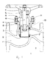
- Fig. 1 shows in axial section a shut-off device in the form of a piston valve.
- Fig. 2 shows in axial section a shut-off device in the form of a plug valve.
- the spool shown in FIG. 1 is a two-way valve with a flow channel 1 ′ formed in the housing 1, which is enclosed by a sealing ring 2. This can be closed in the illustrated closed position by means of an inserted piston 3, which can be displaced by means of a rotatably connected spindle 4.
- the spindle 4 is axially adjustable by means of a threaded piece 5 of an upper part 6 via an actuating member in the form of a handwheel 7.
- the upper part 6 is firmly screwed to the housing 1 by means of studs 8, a tubular extension 6 'of the upper part 6 extending into a bore 11 in the housing 1, which also receives the sealing ring 2, and a cage-like spacer 9 and an annular sealing element 10 for Has sealing to the outside.
- the bore 11 in the area of the sealing element 10 and the spacer 9 has a larger diameter than in the area for receiving the sealing ring 2.
- the shoulder thus formed has a height which corresponds at least to the height of the sealing ring 2 in the delivery state.
- the spacer 9 has a smaller diameter in this hole approach, so that when tightening the studs 8 to the stop of the upper part 6 on the housing 1, the spacer 9 with the outer diameter sits on the bore shoulder and the sealing ring 2 at a specified height and the corresponding Holds density.
- the sealing element 10 Since the sealing element 10 has a greater width, it can be pressed together to compensate for tolerances without, on the one hand, causing excessive frictional resistance on the piston 3 as a result of the lower density, but on the other hand securely holding the sealing ring 2 with greater surface pressure. In this way, the density of the sealing ring 2 can be precisely maintained, which ensures a low frictional resistance with a good seal.
- the sealing ring 2 has the intended higher density so that it is sufficiently against Erosion is assured.
- the sealing ring 2 consists in the example shown of expanded graphite, which was pressed directly as a powder (granules) with a greater height and was pressed to the required height when the upper part 6 was screwed into its stop position.
- the sealing ring 2 is preferably installed higher, ie with a lower density, so that it is pressed axially through the upper part 6 when the piston 3 is pushed in and, as a result, radially deformed and assumes the exact piston dimensions.
- an undersize of max. 0.2 mm can be provided before installing the sealing ring 2. With a larger undersize and with the density ensuring the desired properties, there is otherwise the risk that the sealing ring 2 will be damaged during the movement of the piston 3.
- the sealing ring 2 has a protective ring 2 'at the top and bottom of the end face, the inside diameter of which is only slightly larger than that of the piston 3, so that when the piston 3 emerges from the sealing ring 2, no damage is caused by the medium flowing very quickly with a small gap width can.
- the lower protective ring 2 has the same dimensions as the upper and ensures easy removal of the lower sealing ring 2. At the same time, it is ensured that the sealing ring 2 cannot be installed incorrectly. Since sticking in the sealing ring 2 is to be avoided as far as possible, the protective rings 2 'have nail-like connecting elements which are embedded in the graphite material. To protect against loosening, the nail-like connecting elements can also have barbs.
- the piston valve shown has a good and also for a long time due to the design and selected density for the seals Operating time sufficient sealing ability without the need to re-press the sealing rings, so that therefore no facilities are provided for this; the actuation forces are low and the risk of erosion is largely eliminated.
- the plug valve shown in FIG. 2 has a housing 1, in which a seal made of expanded graphite, designed as a bushing 2, is sealed and secured against rotation. It is molded from expanded graphite powder, which can also be pre-granulated, the specific weight being about 1.6 g / cm3.
- a locking member in the form of a cylindrical plug 3 can be actuated by an actuating member in the form of an attached handle 7, which is connected to the plug 3 via a screw 12 with an interposed locking washer 13.
- the bushing 2 has passages which are protected by metallic insert rings 14. It also forms the holder of a two-part ring 15 which holds the plug 3 axially immovably and is held in place by a screw connection 16.
- a stronger re-pressing of the bush 2 for maintenance reasons is not possible in the example shown because the screw connection has practically no free travel to the housing 1.
- a small free path is advantageous because when the sleeve 2 is clamped by the screw connection 16, no suitable torque can be set for the sleeve 2 without providing particularly precise length tolerances. It must be ensured that the sleeve 2 is really chambered in the plug valve.
- the plug valve shown is therefore practically maintenance-free, and the service life is increased in comparison to the known valves of this type.
Landscapes
- Engineering & Computer Science (AREA)
- General Engineering & Computer Science (AREA)
- Mechanical Engineering (AREA)
- Sealing Devices (AREA)
- Sealing Material Composition (AREA)
- Control And Other Processes For Unpacking Of Materials (AREA)
- Sink And Installation For Waste Water (AREA)
- Processing Of Meat And Fish (AREA)
- Insulators (AREA)
- Taps Or Cocks (AREA)
- Lift Valve (AREA)
- Gasket Seals (AREA)
Applications Claiming Priority (6)
| Application Number | Priority Date | Filing Date | Title |
|---|---|---|---|
| DE3542636 | 1985-12-03 | ||
| DE3542636 | 1985-12-03 | ||
| DE3622889 | 1986-07-08 | ||
| DE3622889 | 1986-07-08 | ||
| DE3631447 | 1986-09-16 | ||
| DE19863631447 DE3631447A1 (de) | 1985-12-03 | 1986-09-16 | Kolbenschieber |
Related Parent Applications (1)
| Application Number | Title | Priority Date | Filing Date |
|---|---|---|---|
| EP86116347A Division EP0248944B1 (fr) | 1985-12-03 | 1986-11-25 | Soupape d'arrêt |
Publications (2)
| Publication Number | Publication Date |
|---|---|
| EP0424360A2 true EP0424360A2 (fr) | 1991-04-24 |
| EP0424360A3 EP0424360A3 (en) | 1991-08-21 |
Family
ID=27193720
Family Applications (2)
| Application Number | Title | Priority Date | Filing Date |
|---|---|---|---|
| EP19910100138 Withdrawn EP0424360A3 (en) | 1985-12-03 | 1986-11-25 | Cut-off apparatus |
| EP86116347A Expired - Lifetime EP0248944B1 (fr) | 1985-12-03 | 1986-11-25 | Soupape d'arrêt |
Family Applications After (1)
| Application Number | Title | Priority Date | Filing Date |
|---|---|---|---|
| EP86116347A Expired - Lifetime EP0248944B1 (fr) | 1985-12-03 | 1986-11-25 | Soupape d'arrêt |
Country Status (7)
| Country | Link |
|---|---|
| US (1) | US5149055A (fr) |
| EP (2) | EP0424360A3 (fr) |
| AT (1) | ATE72602T1 (fr) |
| BR (1) | BR8605888A (fr) |
| DE (1) | DE3683908D1 (fr) |
| ES (1) | ES2028784T3 (fr) |
| TR (1) | TR24769A (fr) |
Cited By (2)
| Publication number | Priority date | Publication date | Assignee | Title |
|---|---|---|---|---|
| WO2015017391A1 (fr) * | 2013-07-29 | 2015-02-05 | Fisher Controls International Llc. | Appareil de soupape fluidique à joints d'étanchéité enserrés |
| CN111527289A (zh) * | 2017-12-12 | 2020-08-11 | 株式会社电装 | 冷却水控制阀装置 |
Families Citing this family (13)
| Publication number | Priority date | Publication date | Assignee | Title |
|---|---|---|---|---|
| DE4306369C2 (de) * | 1993-03-02 | 1995-02-23 | Kempchen & Co Gmbh | Dichtungspackung für Stopfbuchsen an Armaturen und Apparaten |
| DE19526364C1 (de) * | 1995-07-20 | 1996-08-14 | Klinger Ag | Dichtungsring |
| US6102366A (en) * | 1997-09-04 | 2000-08-15 | Perez C.; Sergio | Balanced valve operated by the axial driving of a stem displacing a special elastomeric sealing body |
| US6325159B1 (en) | 1998-03-27 | 2001-12-04 | Hydril Company | Offshore drilling system |
| US6102673A (en) * | 1998-03-27 | 2000-08-15 | Hydril Company | Subsea mud pump with reduced pulsation |
| CH710862B1 (de) | 1999-11-26 | 2016-09-15 | Imerys Graphite & Carbon Switzerland Sa | Verfahren zur Herstellung von Graphitpulvern mit erhöhter Schüttdichte. |
| CN1278439C (zh) * | 2001-10-08 | 2006-10-04 | 蒂米卡尔股份公司 | 电化学电池 |
| US7000898B2 (en) * | 2003-12-09 | 2006-02-21 | Howard Tak Su Lim | Vertical shut-off valve |
| US20060049375A1 (en) * | 2004-09-07 | 2006-03-09 | Fisher Controls International Llc | Boronized valve seal |
| AU2010210501B2 (en) | 2009-02-05 | 2014-02-20 | Flowserve Pte. Ltd. | Pressure-balanced control valves |
| CN102330821B (zh) * | 2011-07-18 | 2013-07-17 | 江苏常盛管业有限公司 | 节水灌溉阀 |
| RU2493461C1 (ru) * | 2012-04-13 | 2013-09-20 | Открытое акционерное общество "Корпорация "Московский институт теплотехники" (ОАО "Корпорация "МИТ") | Клапан для регулирования расхода горячего газа |
| RU181292U1 (ru) * | 2017-03-29 | 2018-07-09 | Закрытое акционерное общество "Курганспецарматура" | Задвижка клиновая |
Family Cites Families (20)
| Publication number | Priority date | Publication date | Assignee | Title |
|---|---|---|---|---|
| AT104270B (de) * | 1924-06-11 | 1926-10-11 | Richard Klinger | Abschlußhahn. |
| US1783762A (en) * | 1927-01-04 | 1930-12-02 | Yarnall Waring Co | Packing for plungers |
| US2097943A (en) * | 1931-11-25 | 1937-11-02 | Zagorski Johann | Valve |
| GB687637A (en) * | 1950-07-03 | 1953-02-18 | Rich Klinger Ag | Improvements in or relating to a piston valve |
| AT212101B (de) * | 1959-09-25 | 1960-11-25 | Rich Klinger Ag | Absperr- oder Drosselvorrichtung |
| GB991581A (en) * | 1962-03-21 | 1965-05-12 | High Temperature Materials Inc | Expanded pyrolytic graphite and process for producing the same |
| US3425663A (en) * | 1966-06-28 | 1969-02-04 | Hills Mccanna Co | Ball valve assembly |
| CA926435A (en) * | 1970-09-21 | 1973-05-15 | V. Adams William | Multilayer graphite seal ring |
| US4068853A (en) * | 1975-09-30 | 1978-01-17 | Union Carbide Corporation | Stuffing box seal |
| US4269391A (en) * | 1977-04-28 | 1981-05-26 | Nippon Petrochemicals Co., Ltd. | Valve sealing device and a valve |
| US4190257A (en) * | 1978-02-01 | 1980-02-26 | Union Carbide Corporation | Packing ring containing flexible graphite |
| FR2452645A1 (fr) * | 1979-03-28 | 1980-10-24 | Cefilac | Nouveau joint dynamique resistant a l'abrasion et a la temperature |
| US4328974A (en) * | 1980-02-19 | 1982-05-11 | White Richard E | Stuffing box packing system and method |
| US4256317A (en) * | 1980-04-24 | 1981-03-17 | Union Carbide Corporation | High-temperature, high-pressure valve packing system |
| FR2509003B1 (fr) * | 1981-07-01 | 1985-07-05 | Cefilac | Joint d'etancheite pour temperatures hautes ou basses en conditions statiques ou dynamiques |
| FI68114C (fi) * | 1982-04-07 | 1985-07-10 | Waertsilae Oy Ab | Taetningsanordning foer ventillock |
| US4394023A (en) * | 1982-09-29 | 1983-07-19 | Daniel Industries Inc. | High temperature valve stem packing with coiled graphite seal rings |
| US4457491A (en) * | 1982-12-09 | 1984-07-03 | Egc Enterprises Incorp. | Extreme-temperature sealing device and annular seal therefor |
| AT382942B (de) * | 1984-01-26 | 1987-04-27 | Klinger Ag | Absperrventil |
| GB2167140B (en) * | 1984-10-17 | 1987-10-28 | Terence Peter Nicholson | Shaft or butterfly valve seal |
-
1986
- 1986-11-25 ES ES198686116347T patent/ES2028784T3/es not_active Expired - Lifetime
- 1986-11-25 EP EP19910100138 patent/EP0424360A3/de not_active Withdrawn
- 1986-11-25 AT AT86116347T patent/ATE72602T1/de not_active IP Right Cessation
- 1986-11-25 EP EP86116347A patent/EP0248944B1/fr not_active Expired - Lifetime
- 1986-11-25 DE DE8686116347T patent/DE3683908D1/de not_active Expired - Fee Related
- 1986-12-02 BR BR8605888A patent/BR8605888A/pt not_active IP Right Cessation
- 1986-12-03 TR TR86/0679A patent/TR24769A/xx unknown
-
1990
- 1990-07-06 US US07/549,359 patent/US5149055A/en not_active Expired - Fee Related
Cited By (3)
| Publication number | Priority date | Publication date | Assignee | Title |
|---|---|---|---|---|
| WO2015017391A1 (fr) * | 2013-07-29 | 2015-02-05 | Fisher Controls International Llc. | Appareil de soupape fluidique à joints d'étanchéité enserrés |
| US9400061B2 (en) | 2013-07-29 | 2016-07-26 | Fisher Controls International Llc | Fluid valve apparatus having enclosed seals |
| CN111527289A (zh) * | 2017-12-12 | 2020-08-11 | 株式会社电装 | 冷却水控制阀装置 |
Also Published As
| Publication number | Publication date |
|---|---|
| ES2028784T3 (es) | 1992-07-16 |
| EP0248944B1 (fr) | 1992-02-12 |
| EP0248944A1 (fr) | 1987-12-16 |
| ATE72602T1 (de) | 1992-02-15 |
| DE3683908D1 (de) | 1992-03-26 |
| EP0424360A3 (en) | 1991-08-21 |
| BR8605888A (pt) | 1987-08-25 |
| TR24769A (tr) | 1992-03-09 |
| US5149055A (en) | 1992-09-22 |
Similar Documents
| Publication | Publication Date | Title |
|---|---|---|
| EP0248944B1 (fr) | Soupape d'arrêt | |
| EP0627582B1 (fr) | Dispositif de joint | |
| DE2241273C2 (de) | Biegsame Dichtung aus Metall | |
| DE60113156T2 (de) | Dichtungssystem | |
| DE3218751A1 (de) | Dichtungseinrichtung | |
| DE1919873B2 (de) | Flachdichtung | |
| DE3403562A1 (de) | Absperrventil | |
| EP0992727A2 (fr) | Arrangement de soupape | |
| DE602004012068T2 (de) | Buchsenloses schaftgesteuertes regelventil | |
| DE4030486A1 (de) | Verbindungsausfuehrung fuer abzweigverbinder in einer hochdruck-kraftstoffschiene | |
| DE1912905B2 (de) | Korrosionsbeständiger Kegelhahn | |
| WO1990014500A1 (fr) | Soupape de limitation de pression comportant un piston a gradins ou un double piston | |
| EP0166855B1 (fr) | Vanne papillon pour fluides agressifs | |
| DE3631447C2 (fr) | ||
| DE19542513C2 (de) | Hohle Kolbenstange für ein Kolben-Zylinderaggregat | |
| DE69113931T2 (de) | Drosselklappe mit Einrichtungen zum Verhindern der Taubildung. | |
| EP0322546B1 (fr) | Robinet à boisseau sphérique | |
| DE3131943C2 (de) | Absperrschieber mit bei der Betätigung im Normalbetrieb axial feststehender Gewindespindel | |
| EP1333342B1 (fr) | Organe de commande de montre comportant un joint d'étanchéité | |
| DE3110839C2 (de) | Armatur zum Leiten und/oder Regeln von Medienströmen | |
| DE3126716A1 (de) | Abdichtanordnung | |
| DE3607736A1 (de) | Absperrklappe | |
| AT379669B (de) | Absperrschieber mit im normalen betrieb unverschiebbarer spindel | |
| DE2834336A1 (de) | Dichtung fuer absperrorgane sowie verfahren zu ihrer herstellung | |
| EP1058797B1 (fr) | Robinet-vanne |
Legal Events
| Date | Code | Title | Description |
|---|---|---|---|
| PUAI | Public reference made under article 153(3) epc to a published international application that has entered the european phase |
Free format text: ORIGINAL CODE: 0009012 |
|
| AC | Divisional application: reference to earlier application |
Ref document number: 248944 Country of ref document: EP |
|
| AK | Designated contracting states |
Kind code of ref document: A2 Designated state(s): AT DE ES FR GB IT SE |
|
| PUAL | Search report despatched |
Free format text: ORIGINAL CODE: 0009013 |
|
| AK | Designated contracting states |
Kind code of ref document: A3 Designated state(s): AT DE ES FR GB IT SE |
|
| 17P | Request for examination filed |
Effective date: 19920208 |
|
| 17Q | First examination report despatched |
Effective date: 19930607 |
|
| STAA | Information on the status of an ep patent application or granted ep patent |
Free format text: STATUS: THE APPLICATION IS DEEMED TO BE WITHDRAWN |
|
| 18D | Application deemed to be withdrawn |
Effective date: 19950530 |