EP0424563A1 - Transporteur horizontal équipé d'un dispositif pour arrêter une palette - Google Patents
Transporteur horizontal équipé d'un dispositif pour arrêter une palette Download PDFInfo
- Publication number
- EP0424563A1 EP0424563A1 EP89119809A EP89119809A EP0424563A1 EP 0424563 A1 EP0424563 A1 EP 0424563A1 EP 89119809 A EP89119809 A EP 89119809A EP 89119809 A EP89119809 A EP 89119809A EP 0424563 A1 EP0424563 A1 EP 0424563A1
- Authority
- EP
- European Patent Office
- Prior art keywords
- pallet
- wedge
- conveyor
- roller
- wedge elements
- Prior art date
- Legal status (The legal status is an assumption and is not a legal conclusion. Google has not performed a legal analysis and makes no representation as to the accuracy of the status listed.)
- Granted
Links
- 238000012545 processing Methods 0.000 claims description 30
- 238000003754 machining Methods 0.000 claims description 10
- 238000011144 upstream manufacturing Methods 0.000 claims description 2
- 238000012986 modification Methods 0.000 description 5
- 230000004048 modification Effects 0.000 description 5
- 238000000034 method Methods 0.000 description 3
- 238000013461 design Methods 0.000 description 2
- 238000011161 development Methods 0.000 description 2
- 230000000284 resting effect Effects 0.000 description 2
- 230000001960 triggered effect Effects 0.000 description 2
- 230000000694 effects Effects 0.000 description 1
- 239000007787 solid Substances 0.000 description 1
Images

Classifications
-
- B—PERFORMING OPERATIONS; TRANSPORTING
- B65—CONVEYING; PACKING; STORING; HANDLING THIN OR FILAMENTARY MATERIAL
- B65G—TRANSPORT OR STORAGE DEVICES, e.g. CONVEYORS FOR LOADING OR TIPPING, SHOP CONVEYOR SYSTEMS OR PNEUMATIC TUBE CONVEYORS
- B65G33/00—Screw or rotary spiral conveyors
- B65G33/02—Screw or rotary spiral conveyors for articles
-
- B—PERFORMING OPERATIONS; TRANSPORTING
- B23—MACHINE TOOLS; METAL-WORKING NOT OTHERWISE PROVIDED FOR
- B23Q—DETAILS, COMPONENTS, OR ACCESSORIES FOR MACHINE TOOLS, e.g. ARRANGEMENTS FOR COPYING OR CONTROLLING; MACHINE TOOLS IN GENERAL CHARACTERISED BY THE CONSTRUCTION OF PARTICULAR DETAILS OR COMPONENTS; COMBINATIONS OR ASSOCIATIONS OF METAL-WORKING MACHINES, NOT DIRECTED TO A PARTICULAR RESULT
- B23Q7/00—Arrangements for handling work specially combined with or arranged in, or specially adapted for use in connection with, machine tools, e.g. for conveying, loading, positioning, discharging, sorting
- B23Q7/005—Lifting devices
-
- B—PERFORMING OPERATIONS; TRANSPORTING
- B23—MACHINE TOOLS; METAL-WORKING NOT OTHERWISE PROVIDED FOR
- B23Q—DETAILS, COMPONENTS, OR ACCESSORIES FOR MACHINE TOOLS, e.g. ARRANGEMENTS FOR COPYING OR CONTROLLING; MACHINE TOOLS IN GENERAL CHARACTERISED BY THE CONSTRUCTION OF PARTICULAR DETAILS OR COMPONENTS; COMBINATIONS OR ASSOCIATIONS OF METAL-WORKING MACHINES, NOT DIRECTED TO A PARTICULAR RESULT
- B23Q7/00—Arrangements for handling work specially combined with or arranged in, or specially adapted for use in connection with, machine tools, e.g. for conveying, loading, positioning, discharging, sorting
- B23Q7/14—Arrangements for handling work specially combined with or arranged in, or specially adapted for use in connection with, machine tools, e.g. for conveying, loading, positioning, discharging, sorting co-ordinated in production lines
- B23Q7/1426—Arrangements for handling work specially combined with or arranged in, or specially adapted for use in connection with, machine tools, e.g. for conveying, loading, positioning, discharging, sorting co-ordinated in production lines with work holders not rigidly fixed to the transport devices
-
- B—PERFORMING OPERATIONS; TRANSPORTING
- B65—CONVEYING; PACKING; STORING; HANDLING THIN OR FILAMENTARY MATERIAL
- B65G—TRANSPORT OR STORAGE DEVICES, e.g. CONVEYORS FOR LOADING OR TIPPING, SHOP CONVEYOR SYSTEMS OR PNEUMATIC TUBE CONVEYORS
- B65G17/00—Conveyors having an endless traction element, e.g. a chain, transmitting movement to a continuous or substantially-continuous load-carrying surface or to a series of individual load-carriers; Endless-chain conveyors in which the chains form the load-carrying surface
- B65G17/002—Conveyors having an endless traction element, e.g. a chain, transmitting movement to a continuous or substantially-continuous load-carrying surface or to a series of individual load-carriers; Endless-chain conveyors in which the chains form the load-carrying surface comprising load carriers resting on the traction element
-
- B—PERFORMING OPERATIONS; TRANSPORTING
- B65—CONVEYING; PACKING; STORING; HANDLING THIN OR FILAMENTARY MATERIAL
- B65G—TRANSPORT OR STORAGE DEVICES, e.g. CONVEYORS FOR LOADING OR TIPPING, SHOP CONVEYOR SYSTEMS OR PNEUMATIC TUBE CONVEYORS
- B65G35/00—Mechanical conveyors not otherwise provided for
- B65G35/06—Mechanical conveyors not otherwise provided for comprising a load-carrier moving along a path, e.g. a closed path, and adapted to be engaged by any one of a series of traction elements spaced along the path
- B65G35/063—Mechanical conveyors not otherwise provided for comprising a load-carrier moving along a path, e.g. a closed path, and adapted to be engaged by any one of a series of traction elements spaced along the path the traction element being a rotating bar or tube
- B65G35/066—Mechanical conveyors not otherwise provided for comprising a load-carrier moving along a path, e.g. a closed path, and adapted to be engaged by any one of a series of traction elements spaced along the path the traction element being a rotating bar or tube the bar or the tube being provided with a helical or annular channel
-
- B—PERFORMING OPERATIONS; TRANSPORTING
- B65—CONVEYING; PACKING; STORING; HANDLING THIN OR FILAMENTARY MATERIAL
- B65G—TRANSPORT OR STORAGE DEVICES, e.g. CONVEYORS FOR LOADING OR TIPPING, SHOP CONVEYOR SYSTEMS OR PNEUMATIC TUBE CONVEYORS
- B65G2201/00—Indexing codes relating to handling devices, e.g. conveyors, characterised by the type of product or load being conveyed or handled
- B65G2201/02—Articles
Definitions
- the invention relates to a device for locking a lying on the conveyor elements of a horizontal conveyor delivered, depending on both sides extending in the conveying direction straight edge rails pallet in a processing position, lifted by the conveyor elements of the conveyor, adjustable by means of a stowable in the conveyor pallets stop.
- the reaching into the processing position pallet abuts against a stop and is then detected by laterally attached grippers and fixed in a slightly raised processing position.
- the object of the invention is to simplify this device.
- both edge rails each have two forming an open to the side wedge angle, extending over the entire edge rail length wedge surfaces which cooperate with there form-fitting matching wedge elements and that wedge elements distributed on both sides along the conveyor track of the wedge surfaces on the processing position, lined up and fixed in place.
- a corresponding development which makes this possible, is characterized in that one or more wedge elements are arranged on both sides at the downstream end of a pallet in the stowed position, that the altitude of the supply position associated wedge elements each side corresponds to the altitude of lying on the straps pallet and that the altitude of the following, the processing position associated wedge elements of the altitude corresponds to one of the straps to a sufficient for decoupling small amount of 0.3 to 10 mm (millimeters), preferably 0.8 mm lifted pallet.
- the wedge members associated with the stowage position desirably adjust the leading end of the pallet in the stowed position to facilitate the infeed of that pallet to the wedge members associated with the processing position.
- the wedge elements associated with the processing position the appropriate fixed in the interest of a solid fixation of the range, based on all spatial directions, fixed.
- pallet For facilitating the lifting of the rear end of a running into the processing position pallet are preferably on both sides two wedge elements each close to the upstream end of the processing position and arranged close to each other.
- the wedge elements may be sliders, but preferably rollers are used to prevent sliding resistance.
- a corresponding embodiment, which is preferred, is characterized in that the wedge surfaces form a roof-shaped, with flattened tip outwardly projecting edge rib and that the wedge elements are rotatable about vertical axes rollers, each having a wedge-shaped circumferential groove.
- Another object of the invention is to increase the speed of change in a device of the type mentioned. This object is achieved in that a conveyor element acting on the pallet in the stowed position is provided for conveying this pallet during the pallet change to the processing position, with a speed which is substantially higher than the conveying speed of the double belt.
- the invention makes use of the fact that the pallets can slide on the double belt, as they do in provision in the known pallet changer, so also can be pushed faster on the double belt than the rotational speed of the double belt corresponds.
- the two provided in the known device, the staging position and in the processing position associated stops, which are also required according to the invention are advantageously structurally integrated into the conveyor element, so that instead of two movable stops as in the prior art, only a single movable conveyor element must drive.
- the corresponding development is characterized in that the conveying element has the two stops and at the beginning of the conveying movement of the conveying element is inoperative and at the end of the conveying movement back into operation.
- a preferred embodiment of such a conveying element which is characterized by a particularly simple structural design and exact positioning of the stops and thus the ready position and in particular the processing position, characterized in that the conveying element is a roller which is rotatably mounted about an axis parallel to the conveying direction , And on its periphery a cooperating with a arranged on the pallet guide member guide coil which extends from the stop for the supply position to the stop for the processing position and 1 to 5, preferably 2 courses.
- the roller is mounted with its axis perpendicular to the center line of the double belt, that the guide coil is a guide, that the guide groove at both ends has a respective stop forming, extending in the circumferential direction groove portion and is open, that the two groove portions extend over the same circumferential angle, that in the guide groove a preferably designed as a guide roller guide element fits, which is mounted below at the longitudinal center of each pallet.
- the located in processing position pallet is carried away as quickly as possible.
- she should overcome her inertia as quickly as possible and record the speed of the double belt. This can be supported by giving this pallet a push at the beginning of the changing process of the conveyor element. This can be achieved very simply by virtue of the fact that the groove section assigned to the machining position opens into an outlet section directed axially parallel with an ejection curve on the rear wall.
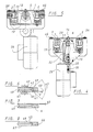
- the horizontal conveyor 1, of which only a short section is shown in Figures 1 and 2 has two endless circulating belts 2 and 3, the upper Trumms are visible in Figure 1 and a horizontal, constantly moving in the direction of arrow 4 pad for there resting Pallets, for example, the pallets 5, 6 and 7 form.
- the pallets are stowable, that is to each pallet, which lies on the straps 2, 3, the subsequent succeed behind and push the front in front of him.
- the pallets 5, 6 and 7 are rectangular, stable plates with double-sided edge rails 8 to 11, which extend in each case over the entire pallet length in the conveying direction according to arrow 4.
- Each pallet has in its longitudinal center 12, at its deliberatelyaufissertigen end, an outstanding on the underside designed as a guide roller driver 13, 14.
- These drivers fit into the guide groove 16 ei ner roller 17 which is rotatably mounted in bearings 37, 38 with its axis 18 in the conveying direction, ie horizontally, under the middle between the straps 2 and 3, which coincides with the longitudinal center 12.
- the bearing 37 is arranged in a lock housing 19 and the bearing 38 in a changer housing 15.
- the two housings 15 and 19 are attached to continuous profile bars of the horizontal conveyor 1.
- a drive motor 20 which drives a cam plate 21 and a coaxial and torsionally secure to the motor output shaft plugged V-belt pulley 22.
- This V-belt pulley drives in a ratio of 1: 2, the V-belt pulley 23, which lies on the roller shaft 24.
- the cam disc 21 has a cam 25, on the other hand, a switch 26 is located, which switches off the drive motor 20 at juxtaposition of the switch to the cam 25.
- a control device not shown, of the horizontal conveyor, performs the cam 21 a full revolution and the roller 17 two full revolutions.
- the roller is drawn at a standstill.
- the guide groove 16 has two full courses.
- the guide groove 16 has at its two ends depending on a circumferentially extending groove portion 29, 30 which is open via an axial inlet portion 32 and an axial outlet portion 31 at the respective end face 33, 34, namely the section 31 with a Austriebskurve 70th ,
- the two groove sections 29 and 30 each form a stop 35, 36.
- the stop 35 fixes the pallet 5 in the machining position and the stop 36 fixes the pallet 6, which is the next in the row of subsequent pallets, in the ready position.
- the two nu tenabête 29, 30 and the two stops 35, 36 extend over the common circumferential angle 39, which thus determines the tolerance for a functional standstill position of the roller 17. This corresponds to the circumferential extent of the cam 25th
- edge rails 8, 9, 10 and 11 of the pallets are, as can be seen particularly well from Figure 6, roof-shaped, with flattened tip outwardly projecting edge ribs, which are formed by two wedge surfaces 40, 41 and an end face 42.
- the wedge surfaces are at an angle 43 to each other and the end face 42 is perpendicular to the support plane defined by the straps 2 and 3 and symmetrical to the wedge surfaces 40, 41.
- the angle 43 is preferably slightly less than ninety degrees.
- the wedge surfaces and the end face extend mirror-symmetrically on both sides over the entire pallet length and are the same for all pallets.
- rollers 45 to 54 To these edge rails fit wedge-shaped circumferential grooves, for example, the circumferential groove 44, of about vertical axes 55, 56 ... rotatably mounted on the housing 19 rollers 45 to 54. These rollers are fixedly mounted on the housing 19, that is, the bearings of the rollers are firmly mounted in the three orthogonal spatial directions. They are rotatable about axes perpendicular to the drawing plane of FIG. 1.
- the rollers 48 to 53 are on the processing position, which occupies the pallet 5, distributed and compared to the altitude, which occupies the resting on the straps 2 and 3 pallet 6, raised by 0.8 mm and arranged so that the located in the processing position Pallet 5 fits snug fit between the rollers 48 to 53 fits.
- the pallet 5 is lifted slightly in this way in their processing position of the straps 2 and 3, so that they no longer touch with the straps and straps no longer grind on this pallet.
- the pallet is orthogonal adjusted in its operating position by the rollers 48 to 53 and fixed in connection with the stop 35 in this machining position.
- the rollers 49 and 54 are at the downstream end of the machining position, which occupies the pallet 6, and have, as seen in Figure 7, a slightly wider circumferential groove, so that for the pallet 6 a small game 60 remains in the vertical direction.
- the pallet 6 In the ready position, the pallet 6 is at the lower end of the game 60 and is for the entry into the processing position otherwise orthogonally preoriented, as shown in Figure 7.
- the pallet 6 When entering the machining position, the pallet 6 is lifted by the rollers 47, 48, 52 and 53 into the machining position and the play 60 allows the height compensation necessary for the pallet entering the machining position.
- the rollers 47, 48, 52, 53 are arranged for lifting the incoming into the processing position pallet in pairs closely adjacent to each other at the very end of the delivery position.
- the height compensation can also be achieved according to a modification in that the rollers 49 and 54 are formed exactly like the other roles, so not with game in the circumferential groove, but on its axis between two end positions defined by stops 61, 62 are movable up and down to an extent as it corresponds to the game 60. These stops are shown in dashed lines in Figure 6 for the sake of simplicity, although they do not belong to the drawn there roller 48, but in this modification to the roller 49 and 54th
- non-rotatable wedge elements may be provided instead of the rollers, along which the edge ribs of the pallets slide along. It then arises, as far as the function is concerned, the same cross-sectional image as in Figure 6 and 7 drawn.
- the operation of the device of Figures 1-7 is the following:
- the pallet change from the position shown in FIG. 1, in which workpieces arranged or mounted on the pallet 5, which are not shown, are processed, is triggered by an external signal from a control device which switches on the motor 20.
- By starting the rotation of the roller gets the driver 13 of the pallet 5 located in the machining position in the axial outlet section 31, receives a push through the ejection curve 70, leaves the guide groove 16 and at the same time the driver 14 of the pallet 6 in the ready position is in the first gear 28 of the guide groove, so that this palette is advanced in the conveying direction 4.
- This feed takes place in accordance with the high speed of the motor 20 at a much higher conveying speed in the direction of arrow 4 than the feed by the slowly circulating belts 2, 3rd
- the pallet 6 is driven in about 0.4 sec. (Seconds) by the roller 17 in the position of the pallet 5 and pushes the pallet 5 in front of him, which then then lowered onto the straps 2, 3 and further promoted by these becomes.
- the webbings would instead of the 0.4 sec. 12.0 sec. Needed to carry the pallet 6 in the processing position.
- the pallet 6 has been lifted on its way to the processing position of the first rollers 48, 53 at the front end and then swung up by the rollers 47, 52 at the rear end and then runs, detached from the straps 2, 3, by the rollers 45, 46, 50, 51 in the drawn for the pallet 5 processing position.
- the feed to the pallet change with much higher speed than the rotational speed of the straps 2 and 3 can be carried out.
- the pallets are fixed in their machining position automatically, solidly, precisely in a predetermined, orthogonally aligned position. It is also noteworthy that for the entire change process, only a single element must be actively adjusted by a drive, namely the roller 17. For the stops no special adjusting members are required because they are integrated into the roller and for lifting and fixing the in processing position pallet located next to their leadership function, the rollers 45 to 54, which need not be specially driven.
Landscapes
- Engineering & Computer Science (AREA)
- Mechanical Engineering (AREA)
- Feeding Of Workpieces (AREA)
- Attitude Control For Articles On Conveyors (AREA)
- Intermediate Stations On Conveyors (AREA)
Priority Applications (5)
| Application Number | Priority Date | Filing Date | Title |
|---|---|---|---|
| DE8989119809T DE58903685D1 (de) | 1989-10-25 | 1989-10-25 | Vorrichtung an einem horizontalfoerderer zum arretieren einer palette. |
| AT89119809T ATE86216T1 (de) | 1989-10-25 | 1989-10-25 | Vorrichtung an einem horizontalfoerderer zum arretieren einer palette. |
| EP89119809A EP0424563B1 (fr) | 1989-10-25 | 1989-10-25 | Transporteur horizontal équipé d'un dispositif pour arrêter une palette |
| DE8913409U DE8913409U1 (de) | 1989-10-25 | 1989-11-14 | Vorrichtung an einem Horizontalförderer zum Arretieren einer Palette |
| JP2284089A JPH03158314A (ja) | 1989-10-25 | 1990-10-22 | 水平に位置するソリッド・パレットを搬送するための装置 |
Applications Claiming Priority (1)
| Application Number | Priority Date | Filing Date | Title |
|---|---|---|---|
| EP89119809A EP0424563B1 (fr) | 1989-10-25 | 1989-10-25 | Transporteur horizontal équipé d'un dispositif pour arrêter une palette |
Publications (2)
| Publication Number | Publication Date |
|---|---|
| EP0424563A1 true EP0424563A1 (fr) | 1991-05-02 |
| EP0424563B1 EP0424563B1 (fr) | 1993-03-03 |
Family
ID=8202060
Family Applications (1)
| Application Number | Title | Priority Date | Filing Date |
|---|---|---|---|
| EP89119809A Expired - Lifetime EP0424563B1 (fr) | 1989-10-25 | 1989-10-25 | Transporteur horizontal équipé d'un dispositif pour arrêter une palette |
Country Status (4)
| Country | Link |
|---|---|
| EP (1) | EP0424563B1 (fr) |
| JP (1) | JPH03158314A (fr) |
| AT (1) | ATE86216T1 (fr) |
| DE (2) | DE58903685D1 (fr) |
Cited By (3)
| Publication number | Priority date | Publication date | Assignee | Title |
|---|---|---|---|---|
| EP0531610A1 (fr) * | 1991-09-10 | 1993-03-17 | BARILLA G. e R. F.lli - Società per Azioni | Dispositif pour le transport d'objets, en particulier de produits alimentaires emballés, d'une station de chargement à une station de déchargement |
| DE4445748A1 (de) * | 1994-12-21 | 1996-06-27 | Weiss Gmbh Sondermaschinentech | Palettenarretiereinrichtung für ein lineares Fördersystem |
| US6070534A (en) * | 1996-03-02 | 2000-06-06 | Koenig & Bauer-Albert Aktiengesellschaft | Conveying system |
Families Citing this family (7)
| Publication number | Priority date | Publication date | Assignee | Title |
|---|---|---|---|---|
| DE4002414A1 (de) * | 1990-01-27 | 1991-08-01 | Krause Johann A Maschf | Verfahren und vorrichtung zum transport von gegenstaenden entlang einer fertigungsstrasse |
| CH680665A5 (fr) * | 1990-05-11 | 1992-10-15 | Menziken Automation | |
| DE4241676C2 (de) * | 1992-12-10 | 1997-07-10 | Fraunhofer Ges Forschung | Verkettungssystem |
| JPH0661834U (ja) * | 1993-02-04 | 1994-09-02 | エフエスイー株式会社 | 搬送パレットの加減速機構 |
| DE4320501C2 (de) * | 1993-06-21 | 1995-09-07 | Sim Zufuehr Und Montagetechnik | Anlage für die Bearbeitung und/oder Montage von auf einem Werkstückträger angeordneten Werkstücken |
| DE4328983C2 (de) * | 1993-08-28 | 1995-08-31 | Sim Zufuehr Und Montagetechnik | Anlage für die Bearbeitung und/oder Montage von auf einem Werkstückträger angeordneten Werkstücken |
| AT411036B (de) * | 1997-11-24 | 2003-09-25 | Sticht Walter | Anlage zur bearbeitung und bzw. oder montage von bauteilen |
Citations (6)
| Publication number | Priority date | Publication date | Assignee | Title |
|---|---|---|---|---|
| FR2071993A1 (fr) * | 1969-12-22 | 1971-09-24 | Giddings & Lewis | |
| US3650373A (en) * | 1969-08-19 | 1972-03-21 | Bosch Gmbh Robert | Conveyor track for assembly line production |
| FR2228012A1 (fr) * | 1973-05-04 | 1974-11-29 | Ossbahr Carl | |
| EP0050080A2 (fr) * | 1980-10-14 | 1982-04-21 | Maurice Prodel | Installation pour l'assemblage et/ou l'usinage de pièces portées par des palettes circulantes et immobilisables |
| DE3224330A1 (de) * | 1982-06-30 | 1984-01-05 | G S A Gesellschaft für Sondermaschinen und Automationsanlagen mbH, 6095 Ginsheim-Gustavsburg | Vorrichtung zum transport von wenigstens einem werkstuecktraeger, insbesondere zur verkettung von maschinen oder arbeitsstationen |
| WO1989010234A1 (fr) * | 1988-04-30 | 1989-11-02 | Siegmund Kumeth | Installation de montage |
Family Cites Families (17)
| Publication number | Priority date | Publication date | Assignee | Title |
|---|---|---|---|---|
| US2279573A (en) * | 1940-10-10 | 1942-04-14 | Western Electric Co | Conveyer system |
| DE957374C (de) * | 1951-12-29 | 1957-01-31 | Gewerk Eisenhuette Westfalia | Gummi- oder Stahlglieder-Foerderband |
| DE1106685B (de) * | 1959-04-30 | 1961-05-10 | Hans Doeppe | Stahlgliederfoerderband |
| DE1756438C3 (de) * | 1968-05-21 | 1975-01-23 | Robert Bosch Gmbh, 7000 Stuttgart | Für Fließfertigung bestimmte Förderbahn |
| JPS5350582A (en) * | 1976-10-19 | 1978-05-09 | Seiko Seiki Co Ltd | Pallet carrying and locating apparatus |
| DE2823188C2 (de) * | 1978-05-27 | 1983-12-29 | Johann A. Krause Maschinenfabrik, 2820 Bremen | Vereinzelungsvorrichtung für auf einem Förderer bewegliche Werkstückträger |
| DE2919488C2 (de) * | 1979-05-15 | 1984-12-06 | Kronseder, Hermann, 8404 Wörth | Vorrichtung zum Vereinzeln von im wesentlichen rechteckigen oder quadratischen Gefäßen, insbesondere in Gefäßbehandlungsmaschinen |
| DE3149307C2 (de) * | 1981-12-12 | 1984-11-15 | Jagenberg-Werke AG, 4000 Düsseldorf | Einteilschnecke für in Reihe zu transportierende Gegenstände, insbesondere Flaschen, insbesondere in einer Etikettiermaschine |
| DE3207460C2 (de) * | 1982-03-02 | 1984-06-20 | Jagenberg-Werke AG, 4000 Düsseldorf | Fördervorrichtung für einer Behandlungsmaschine, insbesondere einer Etikettiermaschine, zuzuführende Gegenstände |
| DE3525656A1 (de) * | 1984-08-08 | 1986-02-13 | Scharmann GmbH & Co, 4050 Mönchengladbach | Bearbeitungszentrum fuer werkstuecke |
| DE3501404A1 (de) * | 1985-01-17 | 1986-07-17 | Focke & Co (GmbH & Co), 2810 Verden | Verfahren und vorrichtung zum zufuehren von packungen zu einer sammel- und verpackungsstation |
| IT1187353B (it) * | 1985-04-12 | 1987-12-23 | Wrapmatic Spa | Dispositivo di accelerazione per la suddivisione di una o piu' file continue di prodotti in gruppi equidistanziati di uno o piu' prodotti |
| DE3618584A1 (de) * | 1986-06-03 | 1987-12-10 | Detlef Dipl Ing Bloecker | Duplex-bandfoerderer |
| DE3725005A1 (de) * | 1987-02-25 | 1989-02-09 | Franz Haane | Positioniervorrichtung fuer in der positioniervorrichtung getragene werkstuecke |
| JPS63267606A (ja) * | 1987-04-24 | 1988-11-04 | Sumitomo Heavy Ind Ltd | バケツトエレベ−タ式連続アンロ−ダ |
| DE3726769A1 (de) * | 1987-08-12 | 1989-02-23 | Grob Gmbh & Co Kg | Vorrichtung zum transport von werkstuecktraegern |
| DE3832845C1 (en) * | 1988-09-28 | 1989-07-20 | Protech Automation Gmbh, 5000 Koeln, De | Assembly station having a positioning and holding apparatus |
-
1989
- 1989-10-25 DE DE8989119809T patent/DE58903685D1/de not_active Expired - Fee Related
- 1989-10-25 EP EP89119809A patent/EP0424563B1/fr not_active Expired - Lifetime
- 1989-10-25 AT AT89119809T patent/ATE86216T1/de not_active IP Right Cessation
- 1989-11-14 DE DE8913409U patent/DE8913409U1/de not_active Expired - Lifetime
-
1990
- 1990-10-22 JP JP2284089A patent/JPH03158314A/ja active Pending
Patent Citations (6)
| Publication number | Priority date | Publication date | Assignee | Title |
|---|---|---|---|---|
| US3650373A (en) * | 1969-08-19 | 1972-03-21 | Bosch Gmbh Robert | Conveyor track for assembly line production |
| FR2071993A1 (fr) * | 1969-12-22 | 1971-09-24 | Giddings & Lewis | |
| FR2228012A1 (fr) * | 1973-05-04 | 1974-11-29 | Ossbahr Carl | |
| EP0050080A2 (fr) * | 1980-10-14 | 1982-04-21 | Maurice Prodel | Installation pour l'assemblage et/ou l'usinage de pièces portées par des palettes circulantes et immobilisables |
| DE3224330A1 (de) * | 1982-06-30 | 1984-01-05 | G S A Gesellschaft für Sondermaschinen und Automationsanlagen mbH, 6095 Ginsheim-Gustavsburg | Vorrichtung zum transport von wenigstens einem werkstuecktraeger, insbesondere zur verkettung von maschinen oder arbeitsstationen |
| WO1989010234A1 (fr) * | 1988-04-30 | 1989-11-02 | Siegmund Kumeth | Installation de montage |
Cited By (3)
| Publication number | Priority date | Publication date | Assignee | Title |
|---|---|---|---|---|
| EP0531610A1 (fr) * | 1991-09-10 | 1993-03-17 | BARILLA G. e R. F.lli - Società per Azioni | Dispositif pour le transport d'objets, en particulier de produits alimentaires emballés, d'une station de chargement à une station de déchargement |
| DE4445748A1 (de) * | 1994-12-21 | 1996-06-27 | Weiss Gmbh Sondermaschinentech | Palettenarretiereinrichtung für ein lineares Fördersystem |
| US6070534A (en) * | 1996-03-02 | 2000-06-06 | Koenig & Bauer-Albert Aktiengesellschaft | Conveying system |
Also Published As
| Publication number | Publication date |
|---|---|
| ATE86216T1 (de) | 1993-03-15 |
| EP0424563B1 (fr) | 1993-03-03 |
| DE8913409U1 (de) | 1989-12-28 |
| DE58903685D1 (de) | 1993-04-08 |
| JPH03158314A (ja) | 1991-07-08 |
Similar Documents
| Publication | Publication Date | Title |
|---|---|---|
| EP0424562B1 (fr) | Echangeur de palettes pour un transporteur horizontal linéaire | |
| EP0154210B1 (fr) | Plieuse à poches | |
| EP0673766A1 (fr) | Dispositif pour traiter du matériau en couche ou similaire | |
| DE3112911A1 (de) | Montagesystem | |
| DE4026098C1 (en) | Room partition of displaceable wall elements - which have support bolts, each horizontally, slidably mounted w.r.t. another one | |
| DE69401444T2 (de) | Vorrichtung zum automatischen Einstellen eines Becherförderers gemäss der Grösse der zu fördernden Gegenstände, und Förderer zur Ausübung des Verfahrens | |
| EP0424563A1 (fr) | Transporteur horizontal équipé d'un dispositif pour arrêter une palette | |
| CH656864A5 (de) | Vorrichtung zum einstellen von stapelvorrichtungselementen einer einrichtung zum stapeln von papierboegen und verfahren zum betrieb derselben. | |
| DE4409780C2 (de) | Mehrstationenbearbeitungsanlage für Werkstücke mit einer ebenen Standfläche | |
| EP0936498B1 (fr) | Dispositif de coupe pour une bande | |
| DE3430029C2 (de) | Einrichtung zum Beschicken von Buntaufteilsägemaschinen mit auf einem Hubtisch angeordneten tafel- bzw. plattenförmigen Werkstücken | |
| EP2046544B1 (fr) | Dispositif de fabrication et/ou d'usinage de panneaux | |
| DE2248193A1 (de) | Vorrichtung zum speichern von werkstuecken, insbesondere tuben | |
| DE3224330A1 (de) | Vorrichtung zum transport von wenigstens einem werkstuecktraeger, insbesondere zur verkettung von maschinen oder arbeitsstationen | |
| DE1652760B2 (de) | Fuer eine tafelschere fuer tafeln aus blech, kunststoff o.dgl. bestimmte vorrichtung zum unterstuetzen und abfuehren der geschnittenen tafeln | |
| DE20118340U1 (de) | Vorrichtung zum maßgenauen Schneiden von bandförmigen Materialien | |
| DE19546887A1 (de) | Förderbahn für Paletten | |
| DE2952264C2 (fr) | ||
| DE3242484C1 (de) | Transportvorrichtung fuer laengliche Werkstuecke | |
| DE3327747A1 (de) | Vorrichtung zum zufuehren von stangenfoermigem stueckgut | |
| EP0126707A1 (fr) | Dispositif pour emmagasiner des objets plats, étant de préférence ronds | |
| DE854642C (de) | Einrichtung zum Falten von Textiltuechern | |
| EP1218271B1 (fr) | Dispositif pour tourner une pile de papier | |
| EP1256416B1 (fr) | Entraînement à manivelle pour ramener des pièces usinées à la station de départ | |
| EP0457720B1 (fr) | Dispositif d'alimentation pour une machine pour l'assemblage de feuilles de placage en bande continue |
Legal Events
| Date | Code | Title | Description |
|---|---|---|---|
| PUAI | Public reference made under article 153(3) epc to a published international application that has entered the european phase |
Free format text: ORIGINAL CODE: 0009012 |
|
| 17P | Request for examination filed |
Effective date: 19900809 |
|
| AK | Designated contracting states |
Kind code of ref document: A1 Designated state(s): AT BE CH DE ES FR GB GR IT LI LU NL SE |
|
| 17Q | First examination report despatched |
Effective date: 19920714 |
|
| GRAA | (expected) grant |
Free format text: ORIGINAL CODE: 0009210 |
|
| AK | Designated contracting states |
Kind code of ref document: B1 Designated state(s): AT BE CH DE ES FR GB GR IT LI LU NL SE |
|
| PG25 | Lapsed in a contracting state [announced via postgrant information from national office to epo] |
Ref country code: IT Free format text: LAPSE BECAUSE OF FAILURE TO SUBMIT A TRANSLATION OF THE DESCRIPTION OR TO PAY THE FEE WITHIN THE PRE;WARNING: LAPSES OF ITALIAN PATENTS WITH EFFECTIVE DATE BEFORE 2007 MAY HAVE OCCURRED AT ANY TIME BEFORE 2007. THE CORRECT EFFECTIVE DATE MAY BE DIFFERENT FROM THE ONE RECORDED.SCRIBED TIME-LIMIT Effective date: 19930303 Ref country code: ES Free format text: THE PATENT HAS BEEN ANNULLED BY A DECISION OF A NATIONAL AUTHORITY Effective date: 19930303 Ref country code: BE Effective date: 19930303 Ref country code: SE Effective date: 19930303 Ref country code: GR Free format text: LAPSE BECAUSE OF FAILURE TO SUBMIT A TRANSLATION OF THE DESCRIPTION OR TO PAY THE FEE WITHIN THE PRESCRIBED TIME-LIMIT Effective date: 19930303 Ref country code: GB Effective date: 19930303 Ref country code: NL Effective date: 19930303 Ref country code: FR Effective date: 19930303 |
|
| REF | Corresponds to: |
Ref document number: 86216 Country of ref document: AT Date of ref document: 19930315 Kind code of ref document: T |
|
| REF | Corresponds to: |
Ref document number: 58903685 Country of ref document: DE Date of ref document: 19930408 |
|
| EN | Fr: translation not filed | ||
| NLV1 | Nl: lapsed or annulled due to failure to fulfill the requirements of art. 29p and 29m of the patents act | ||
| GBV | Gb: ep patent (uk) treated as always having been void in accordance with gb section 77(7)/1977 [no translation filed] |
Effective date: 19930303 |
|
| PG25 | Lapsed in a contracting state [announced via postgrant information from national office to epo] |
Ref country code: AT Effective date: 19931025 |
|
| PG25 | Lapsed in a contracting state [announced via postgrant information from national office to epo] |
Ref country code: CH Effective date: 19931031 Ref country code: LU Free format text: LAPSE BECAUSE OF NON-PAYMENT OF DUE FEES Effective date: 19931031 Ref country code: LI Effective date: 19931031 |
|
| PLBE | No opposition filed within time limit |
Free format text: ORIGINAL CODE: 0009261 |
|
| STAA | Information on the status of an ep patent application or granted ep patent |
Free format text: STATUS: NO OPPOSITION FILED WITHIN TIME LIMIT |
|
| 26N | No opposition filed | ||
| REG | Reference to a national code |
Ref country code: CH Ref legal event code: PL |
|
| PG25 | Lapsed in a contracting state [announced via postgrant information from national office to epo] |
Ref country code: DE Effective date: 19940701 |