EP0424566A1 - Machine à pilonner plus particulièrement pour la cokerie - Google Patents
Machine à pilonner plus particulièrement pour la cokerie Download PDFInfo
- Publication number
- EP0424566A1 EP0424566A1 EP89119836A EP89119836A EP0424566A1 EP 0424566 A1 EP0424566 A1 EP 0424566A1 EP 89119836 A EP89119836 A EP 89119836A EP 89119836 A EP89119836 A EP 89119836A EP 0424566 A1 EP0424566 A1 EP 0424566A1
- Authority
- EP
- European Patent Office
- Prior art keywords
- arm
- clamping
- frame
- tamper
- machine according
- Prior art date
- Legal status (The legal status is an assumption and is not a legal conclusion. Google has not performed a legal analysis and makes no representation as to the accuracy of the status listed.)
- Withdrawn
Links
- 238000004939 coking Methods 0.000 title description 4
- 230000007246 mechanism Effects 0.000 claims abstract description 24
- 230000003578 releasing effect Effects 0.000 claims abstract description 9
- 230000002040 relaxant effect Effects 0.000 claims description 5
- 239000000571 coke Substances 0.000 claims description 4
- 239000000463 material Substances 0.000 abstract description 3
- 239000003245 coal Substances 0.000 description 5
- 238000010276 construction Methods 0.000 description 4
- 239000012634 fragment Substances 0.000 description 4
- 241000273930 Brevoortia tyrannus Species 0.000 description 3
- OKTJSMMVPCPJKN-UHFFFAOYSA-N Carbon Chemical compound [C] OKTJSMMVPCPJKN-UHFFFAOYSA-N 0.000 description 2
- 229910052799 carbon Inorganic materials 0.000 description 2
- 230000000694 effects Effects 0.000 description 1
- 238000004519 manufacturing process Methods 0.000 description 1
- 230000003068 static effect Effects 0.000 description 1
Images


Classifications
-
- C—CHEMISTRY; METALLURGY
- C10—PETROLEUM, GAS OR COKE INDUSTRIES; TECHNICAL GASES CONTAINING CARBON MONOXIDE; FUELS; LUBRICANTS; PEAT
- C10B—DESTRUCTIVE DISTILLATION OF CARBONACEOUS MATERIALS FOR PRODUCTION OF GAS, COKE, TAR, OR SIMILAR MATERIALS
- C10B45/00—Other details
- C10B45/02—Devices for producing compact unified coal charges outside the oven
Definitions
- the invention relates to a ramming machine, in particular for coke oven purposes, with at least one tamper with a rod, on the two sides of which are arranged clamping elements of the lifting mechanism and additional elements of the supporting and releasing mechanism of the ramming mechanism.
- the coke pounding machine known from Polish Patent No. 261947 for compressing the coal mass intended for coking has a mobile frame arranged on rails, a lowering mechanism being provided in its lower part and a tamper at the assumed height above the coke mass in the tamping chamber.
- the elevator has an electric motor which is connected to the tooth reduction valve, the output gearwheels of which interact with gearwheels which are arranged on two drive shafts but are mounted on both sides of the tamper rods.
- Each drive shaft has clamping elements in the form of drive disks with a shape similar to a circular section, which interact with the friction lining on both rod sides.
- Each drive shaft is rotatably mounted in rows of double rockers, the upper rockers of which are articulated to the frame and the lower rockers of which are pivotally attached to the rocker arms, which are rotatably attached to the rocker of the machine on the two-piece shaft, the two-piece shaft being levered with the piston rod of the control motor is connected.
- the rod of every pounder is located between idlers mounted on the frame of the ramming machine.
- the upper part of the ramming machine frame has a support and release mechanism for the rammers.
- This factory is equipped with a control motor, the cylinders of which are pivotally mounted to the body of the reducing valve and the piston rod, which is connected to the two-part shaft rotatably attached to the frame of the machine.
- the two-part shaft is equipped with a resistance rocker for each tamper and each of the rockers is connected to a corresponding stop, which is in a system which is formed by two levers arranged on both sides of the rod of the rammer, which are interconnected by the Connectors are connected.
- Each lever is mounted on a single shaft that is rotatably mounted on the frame and on a corresponding rod side of the rammer.
- Each lever shaft is equipped with a frame in which a clamping element is rotatably mounted as a clamping blade, which interacts with the friction lining on the tamper rod.
- the lever system is connected to the relaxing spring by a cooperating mandrel and each rod is located between idlers attached to the machine frame.
- the object of the invention is to change the construction of the known ramming machines in such a way that it contains no friction drive pulleys of the elevator and no rotatable clamping blades of the support and release mechanism of the rammers. It should also be possible to manufacture the ramming machine from any number of identical ramming construction elements with a common drive.
- the ram of the rammer is provided with a clamping arm with a passage opening in which there are clamping elements which are displaced relative to one another to the rod axis of the rammer, the opening having compensation inserts.
- the clamping arm is articulated to the extension arm attached to the machine frame, which interacts with the drive arm with a rotating roller.
- the drive arm is attached to the drive shaft on the frame and connected to the rotatable hydraulic motor, the clamping arm having a guide piece provided in the rotating roller.
- the tamper's lifting and releasing mechanism is equipped with a two-armed clamping lever, the arm on the inside of which has a passage opening in which there are clamping elements that are displaced relative to the tamping rod axis, as well as compensation inserts, and the lever arm on the outside has a relaxing effect on the one hand acting element in the form of a spring and on the other hand together with the support arm rotatably attached to the shaft on the machine frame.
- the tamper bar is equipped with a limiter for the maximum height of the tamper elevation and the tamper bar guiding rollers have a cutout corresponding to the limiter, at least one roller being fastened in eccentric sleeves which are rotatably mounted in the machine frame.
- the ramming machine according to the invention is characterized by a simple construction and relatively low weight and contains no friction linings and is easy to maintain and operate in terms of its construction similarity and the mode of operation of its mechanisms.
- the ramming machine can be made from any number of structurally identical elements, each of which contains a rammer, a lifting, supporting and releasing mechanism of the rammer, which enables it to be used optimally according to the needs of the coking plant.
- the machine can be driven by a hydraulic motor, which makes a tooth reduction valve unnecessary, or it can be driven by an electric motor, then it must be equipped with a tooth reduction valve.
- the control of the support and release mechanism of the tamper can be carried out centrally with the help of any mechanical drive or by hand, whereby by equipping the rod with a limiter it was possible to automatically hold the tamper at the assumed maximum lifting height when the lifting device was active , which eliminates a complicated and unreliable system of automatic control.
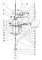
- the frame 1 of the machine contains a lifting mechanism of the rammer 2 in the upper part and a support and release mechanism for the rammer in the lower part.
- the support structure is equipped with a clamping arm 3 with the passage opening 4, in which clamping elements 5 are located on both sides of the rod 6 of the rammer 2 and which are displaced towards one another towards the rod axis of the rammer.
- the opening has 4 inserts 7 for the play compensation between the rod 6 and the clamping elements 5 made of a hard material.
- the clamp arm 3 is articulated through the connector 8 to the arm 9 which is articulated to the frame 1 and which cooperates with the drive arm 11 with the rotating roller 10: the drive arm is fixed to the drive shaft 12 which is rotatably attached to the frame 1 and is directly connected to the rotatable hydraulic motor 13 or to the electric motor through the tooth reduction valve (not shown in the drawing). If the ramming machine has more than one tamper 2, the drive shaft 12 is equipped jointly and with drive arms 11 arranged at an angle to one another, each of which interacts with the arm 9 of the elevator of a specific tamper 2 assigned to it.
- the clamp arm 3 is also equipped with a guide track 14 with the rotating roller 15, it being useful for the clamp arm (in the initial position) to be on the housing 16, which is arranged on the upper support arm 17 which attaches to the frame 1 of the machine is.
- the lifting and releasing mechanism of the rammer 2 installed in the lower part of the frame 1 is equipped with a two-armed clamping lever 18, which has an inner arm 20 fitted inside the lower support arm 19 and an outer arm 21 which is articulated to the frame 1 by the connector 22.
- the inner arm 20 of the clamping lever 18 has a passage opening 23 in which there are two clamping elements 24 on both sides of the rod 6, which are displaced relative to one another to the rod axis and have cutouts 25 which ensure the passage on the rod 6 of the limiter 26 for the maximum Allow height of the ram lift 2, 23 inserts 27 for the play compensation between the rod 6 and clamping elements 24 are made of the hard material in the passage opening.
- the outer arm 21 of the clamping lever interacts on the one hand with the relaxing spring 28 which is attached to the lower support arm 19 on the frame 1 and on the other hand is attached to the arm 29 with the rotating roller, the inner arm 20 of the clamping lever with the interconnect 31 on Frame 1 of the machine interacts.
- the arm 29 is fixed to the shaft 32 which is rotatably attached to the frame 1, and is articulated by the connector 32 to the piston rod of the control motor 34 on the frame 1. If the ramming machine has more than one tamper 2, the shaft 32 is equipped with such a number of arms 29 as there are rammers.
- the upper support arm 17 on the frame 1 comprises upper guide rollers 35 and the lower support arm 19 lower guide rollers 36 for the rod 6 of the rammer 2, at least one lower guide roller 36 and at least one upper guide roller 35 being mounted on the shaft 37, which are in eccentric sleeves 38 are attached, which are rotatably mounted in the frame 1 of the machine and allows regulation of the removal of the upper and lower rollers, the guide rollers 35, 36 having cutouts that allow the passage of the limiter 26 on the Allow rod 6 of the rammer.
- the frame 1 is equipped with wheels 40.
- the ramming machine shown in the exemplary embodiment works as follows: in order to compress the carbon mass 41 in the ramming chamber 42, the tamper 2 is raised to the maximum height by the lifting mechanism, then it is let down freely onto the carbon mass by the supporting and releasing mechanism of the ramming mechanism , whereby the tamper is blocked during breaks in machine operation and can be held in the upper position by this work for any length of time.
- the arm 29 is released by the shaft rotation 32 with the aid of a control motor 34, then the outer arm 21 of the clamping lever 18 assumes the position shown by broken lines in FIG. 2 under the action of the spring.
- an automatic rod clamping 6 of the rammer takes place between the clamping elements 24 with a force which enables the rammer to fall under the effect of its own weight.
- the ram of the rammer is started by starting the motor 13 in such a way that the direction of rotation of the drive arm 11 is in the direction shown by the arrow in FIG. 1.
- the clamping arm moves into the initial position when the arm 9 falls on the rod 6, but when this arm is lifted, the rod is automatically clamped between the clamping elements 5 of the clamping arm 3 and the arm by the distance H up to the position drawn with broken lines in FIG. 1.
- the tamper is raised by the same distance H until the moment when the clamping arm 3 with clamping elements 5 does not push on the rod 6 when the arm 9 falls, but without cutouts to the limiter 26, which is stopped in the upper maximum tamper position 2.
- the arm 9 continues to move until the clamping arm 3 is at the same height (on the limiter 26) and moves in an oscillating manner.
- the elevator is stopped by switching off the motor 13, then the tamper 2 are held in the upper position by clamping lever 18.
- the shaft 32 is partially rotated so that its arm 29 brings the outer arm 21 of the clamping lever into the position with lines in the position shown in FIG. 1 and causes the clamping of the spring 28 and then on automatic ramming of the rammer onto the coal mass 41 is effected, after which the next cycle of ramming lifting can be started.
Landscapes
- Chemical & Material Sciences (AREA)
- Engineering & Computer Science (AREA)
- Materials Engineering (AREA)
- Oil, Petroleum & Natural Gas (AREA)
- Organic Chemistry (AREA)
- Road Paving Machines (AREA)
Priority Applications (2)
| Application Number | Priority Date | Filing Date | Title |
|---|---|---|---|
| CS575989A CS274555B2 (en) | 1989-10-11 | 1989-10-11 | Upsetting machine especially for coking plants |
| EP89119836A EP0424566A1 (fr) | 1989-10-11 | 1989-10-25 | Machine à pilonner plus particulièrement pour la cokerie |
Applications Claiming Priority (2)
| Application Number | Priority Date | Filing Date | Title |
|---|---|---|---|
| CS575989A CS274555B2 (en) | 1989-10-11 | 1989-10-11 | Upsetting machine especially for coking plants |
| EP89119836A EP0424566A1 (fr) | 1989-10-11 | 1989-10-25 | Machine à pilonner plus particulièrement pour la cokerie |
Publications (1)
| Publication Number | Publication Date |
|---|---|
| EP0424566A1 true EP0424566A1 (fr) | 1991-05-02 |
Family
ID=25746242
Family Applications (1)
| Application Number | Title | Priority Date | Filing Date |
|---|---|---|---|
| EP89119836A Withdrawn EP0424566A1 (fr) | 1989-10-11 | 1989-10-25 | Machine à pilonner plus particulièrement pour la cokerie |
Country Status (2)
| Country | Link |
|---|---|
| EP (1) | EP0424566A1 (fr) |
| CS (1) | CS274555B2 (fr) |
Cited By (3)
| Publication number | Priority date | Publication date | Assignee | Title |
|---|---|---|---|---|
| CN101967384A (zh) * | 2010-11-01 | 2011-02-09 | 大连华宇冶金设备有限公司 | 夹板锤捣固机 |
| CN102559217A (zh) * | 2010-12-07 | 2012-07-11 | 张立新 | 一种煤饼捣固技术 |
| CN106381157A (zh) * | 2016-09-20 | 2017-02-08 | 鞍钢股份有限公司 | 一种提高焦炉装煤堆密度的压实装置及方法 |
Citations (2)
| Publication number | Priority date | Publication date | Assignee | Title |
|---|---|---|---|---|
| DE243463C (fr) * | ||||
| DE169079C (fr) * |
-
1989
- 1989-10-11 CS CS575989A patent/CS274555B2/cs unknown
- 1989-10-25 EP EP89119836A patent/EP0424566A1/fr not_active Withdrawn
Patent Citations (2)
| Publication number | Priority date | Publication date | Assignee | Title |
|---|---|---|---|---|
| DE243463C (fr) * | ||||
| DE169079C (fr) * |
Cited By (5)
| Publication number | Priority date | Publication date | Assignee | Title |
|---|---|---|---|---|
| CN101967384A (zh) * | 2010-11-01 | 2011-02-09 | 大连华宇冶金设备有限公司 | 夹板锤捣固机 |
| CN101967384B (zh) * | 2010-11-01 | 2014-05-07 | 大连华宇冶金设备有限公司 | 夹板锤捣固机 |
| CN102559217A (zh) * | 2010-12-07 | 2012-07-11 | 张立新 | 一种煤饼捣固技术 |
| CN106381157A (zh) * | 2016-09-20 | 2017-02-08 | 鞍钢股份有限公司 | 一种提高焦炉装煤堆密度的压实装置及方法 |
| CN106381157B (zh) * | 2016-09-20 | 2019-09-20 | 鞍钢股份有限公司 | 一种提高焦炉装煤堆密度的压实装置及方法 |
Also Published As
| Publication number | Publication date |
|---|---|
| CS274555B2 (en) | 1991-08-13 |
| CS575989A2 (en) | 1990-10-12 |
Similar Documents
| Publication | Publication Date | Title |
|---|---|---|
| DE69902016T2 (de) | Walzgerüst mit drei oder mehr ausschwenkbaren und einstellbaren tragarmen | |
| EP0005760B1 (fr) | Machine pour le redressage de tôles et de bandes | |
| EP0536528A1 (fr) | Dispositif de manoeuvre d'une porte pivotante-coulissante pour véhicules de transport en commun, notamment ferroviaires | |
| EP1119428B1 (fr) | Systeme de fermeture coulissant pour recipient contenant du metal fondu | |
| DE10347571B4 (de) | Druckwerk | |
| EP1375409B1 (fr) | Dispositif de levage à ciseaux pour une installation de convoyage à rouleaux | |
| DE69300087T2 (de) | Vorrichtung zur Einstellung der Schafthöhenlage bei Exzenterschaftmaschinen. | |
| DE29913898U1 (de) | Rollenausbildung zur Verschiebung von Eisenbahn-Weichenschienen | |
| DD219809A5 (de) | Gleisbaumaschine, deren fahrgestell mit einer vorrichtung zum heben und richten eines gleises ausgeruestet ist | |
| CH671527A5 (fr) | ||
| DE2247061A1 (de) | Blechrundbiegemaschine | |
| CH658275A5 (de) | Stopfaggregat fuer gleisstopfmaschinen. | |
| EP0339375A1 (fr) | Machine pour le traitement de la viande | |
| EP0483599A2 (fr) | Cage de laminoir comprenant des dispositifs pour supporter à distance le cylindre de travail supérieur | |
| DE3825100C2 (de) | Vorrichtung zum Öffnen des Abstichloches eines Schachtofens | |
| DE1215096B (de) | Vorrichtung zum walzenachsparallelen Verschieben von Zwischenstuecken zwischen den Einbaustuecken und den Anstellspindeln von Walzgeruesten | |
| DE927951C (de) | Aufzug fuer Fahrzeuge od. dgl. | |
| DE1914051A1 (de) | Kantenwalzgeruest fuer Stahlbrammen od.dgl. | |
| DE3812335A1 (de) | Zwangsfuehrung fuer paare von kurbelgetriebenen hub-, schub- und/oder zugelementen zur erzeugung einer parallelen linearen bewegung ihrer freien enden | |
| DE2630443C2 (de) | Vorschubvorrichtung für Gewinnungsmaschinen des Untertagebergbaues, insbesondere für Walzenschrämmaschinen | |
| DE709978C (de) | Walzgutueberhebetisch, insbesondere fuer Fein- und Mittelblechwalzwerke | |
| DE1561730C3 (de) | Vorrichtung zum Auswechseln einer elastischen Kalanderwalze in einem Kalander | |
| DE3112810C2 (fr) | ||
| DE867436C (de) | Automatische Tablettenpressmaschine | |
| DE20114801U1 (de) | Transporteinrichtung für Palettenwagen |
Legal Events
| Date | Code | Title | Description |
|---|---|---|---|
| PUAI | Public reference made under article 153(3) epc to a published international application that has entered the european phase |
Free format text: ORIGINAL CODE: 0009012 |
|
| AK | Designated contracting states |
Kind code of ref document: A1 Designated state(s): DE FR GB |
|
| STAA | Information on the status of an ep patent application or granted ep patent |
Free format text: STATUS: THE APPLICATION HAS BEEN WITHDRAWN |
|
| 18W | Application withdrawn |
Withdrawal date: 19911008 |