EP0424603B1 - Guide-fil pour machine du type à fil mobile - Google Patents
Guide-fil pour machine du type à fil mobile Download PDFInfo
- Publication number
- EP0424603B1 EP0424603B1 EP90109903A EP90109903A EP0424603B1 EP 0424603 B1 EP0424603 B1 EP 0424603B1 EP 90109903 A EP90109903 A EP 90109903A EP 90109903 A EP90109903 A EP 90109903A EP 0424603 B1 EP0424603 B1 EP 0424603B1
- Authority
- EP
- European Patent Office
- Prior art keywords
- wire
- collar
- guide
- support member
- die guide
- Prior art date
- Legal status (The legal status is an assumption and is not a legal conclusion. Google has not performed a legal analysis and makes no representation as to the accuracy of the status listed.)
- Expired - Lifetime
Links
Images



Classifications
-
- B—PERFORMING OPERATIONS; TRANSPORTING
- B23—MACHINE TOOLS; METAL-WORKING NOT OTHERWISE PROVIDED FOR
- B23H—WORKING OF METAL BY THE ACTION OF A HIGH CONCENTRATION OF ELECTRIC CURRENT ON A WORKPIECE USING AN ELECTRODE WHICH TAKES THE PLACE OF A TOOL; SUCH WORKING COMBINED WITH OTHER FORMS OF WORKING OF METAL
- B23H7/00—Processes or apparatus applicable to both electrical discharge machining and electrochemical machining
- B23H7/02—Wire-cutting
- B23H7/08—Wire electrodes
- B23H7/10—Supporting, winding or electrical connection of wire-electrode
Definitions
- the present invention relates to the wire guides of wire type electrical discharge machining devices (hereinafter referred to as "wirecut EDMs”) and especially to an improved support structure for the die guides.
- wirecut EDMs wire type electrical discharge machining devices
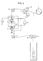
- Fig. 4 illustrates an example of a wirecut EDM of the prior art.
- numeral 1 indicates a wire electrode fed from a supply bobbin 2; 3, a brake roller directly coupled with an electromagnetic brake 3a for providing a predetermined tension on the wire electrode 1; and 4a, 4b and 4c, idlers for changing the running direction of the wire electrode 1.
- At 5 is a first top wire guide; 6 indicates a second top wire guide; 7, a top energizer; 8, a top dielectric nozzle; 9, a first bottom wire guide; and 10, a second bottom wire guide.
- At 11 is a bottom energizer; 12 indicates a bottom dielectric nozzle; 13, a pump for supplying the dielectric; 14, a pulse power supply unit for supplying a pulse voltage to a gap between the wire electrode 1 and the workpiece 15 via energizers 7 and 11; and 16, a wire feed roller.
- the wirecut EDM of said structure functions as follows: First, the wirecut EDM ejects dielectric from the nozzles 8 and 12 in the same axial direction as the wire electrode 1, while simultaneously applying a pulse voltage to a gap between the wire electrode 1 and the workpiece 15 from the pulse power supply unit 14. At the small gap between the wire electrode 1 and the workpiece 15, electrical discharge repeatedly occurs through the medium of the dielectric to melt and cut the workpiece 15 by means of the thermal energy generated at the time of electrical discharge incidental to the vaporization and explosion of the dielectric.
- Relative motion between the wire electrode 1 and the workpiece 15 is generally carried out by controlling an X-Y table (not illustrated) numerically.
- an X-Y table (not illustrated) numerically.
- the wire electrode 1 is pressed against the energizers 7 and 10 by the second top wire guide 6 and second bottom wire guide 10 and runs while simultaneously sliding against the energizers 7 and 10.
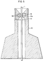
- Fig. 5 illustrates detailed examples of the first top wire guide 5 and the first bottom wire guide 9 in the prior art shown in Fig. 4.
- the structure shown in Fig. 5 has been disclosed in Kokai Nos. 1981-3148 or 1982-121420, for example.
- the numeral 100 indicates a die guide made of an extremely hard material such as diamond or sapphire. Its center is a bearing 100a abutting and supporting the wire electrode 1. The portion gradually increasing in diameter from the center to the upper end is the approach 100b.
- a support member which encloses and centers the die guide.
- a case 102 accommodates and secures the die guide 100 and the support member 101.
- a pair of wire guides are located on both sides of the workpiece, the workpiece and the pair of top and bottom wire guides are moved relatively to each other by numerical control, and at the same time, pulsed electrical energy and dielectric are supplied to a gap between the wire electrode and the workpiece to generate repeated electrical discharge, erode the workpiece locally, and machine a desired contour with high accuracy. Accordingly, displacement at the support point of the wire electrode must be minimized, and the clearance between the bearing 100a and the wire electrode 1 must be designed to be extremely small, generally between approximately 2 and 10 ⁇ m.
- the electrode 1 is pulled from the wire supply bobbin 2 in a predetermined wire electrode path including the said wire guides 100.
- the above process may either be performed manually or automatically using a wire electrode supplier. In either case, for the above reason, it is not easy to insert the wire electrode 1 into the die guide 100 because of the small clearance.
- the approach 100b is designed to have a conically smooth curve, and similarly, the inside of the support member 101 is conically shaped to gradually decrease in diameter toward the approach 100b.
- the insides of the die guide 100 and the support member 101 are finished to an extremely smooth surface roughness (e.g. about 1.2 ⁇ ), and the abutment of the die guide 100 and the support member 101 is curved continuously so that no reverse step occurs in the insertion direction of the wire electrode 1.
- the wire guide of the prior art is generally made in a manufacturing process illustrated in Fig. 6 to form a smooth guide surface without generating a step between the die guide 100 and the support member 101. In Fig.
- (a) indicates the process of grinding the top and bottom surfaces of a gemstone, such as diamond or sapphire, in parallel;
- (b) is a process of covering the die guide 100 and performing sintering using a powdered metal (e.g. WC-CO);
- (c) illustrates the process of drilling the sintered body by laser cutting, etc .
- (d) shows the process of forming a desired shape by ultrasonic machining, etc .;
- (e) is a lapping process ( e.g. first the machined surface is lapped with grit of 3 to 6 ⁇ diameter, then with grit of 0 to 1/4 ⁇ diameter) for improving the surface roughness and smoothing the cut surface.
- the process may use metal wires, diamond grit, etc .
- the wirecut EDM of the prior art employs a support member 101 formed through metal powder sintering, which is high in machinability as well as mechanical strength, for holding the die guide 100. High mechanical strength is needed to permit the wire guide to sustain the large mechanical forces, such as lateral forces, encountered during machining.
- the prior art support member 101 will be corroded as shown in Fig. 7. Several factors cause this corrosion. The first factor is an electro-corrosion effect created by the coaction of sludge and water.
- wirecut EDMing electrical discharge occurs in the gap between the workpiece 105 and the wire electrode 1, and part of the workpiece 105 and the wire electrode 1 enter into the dielectric as sludge during dissolution and cooling.
- This sludge floats in the dielectric during EDMing, but when EDMing stops, it remains in the conical recess formed by the wire guide support member 101 and the die guide 100, and a lot of sludge sinks to the neighborhood of the die guide 100.
- the dielectric stays in the recess due to its surface tension for a long period of time. For this reason, in the neighborhood of the die guide 100, corrosion is prone to progress by local electrochemical action.
- the second contribution to corrosion is attributable to the polarization of the wire electrode 1 and the support member 101, which is assumed to dissolve the positive pole or generate micro-electrical discharges. If the aforementioned corrosion progresses, a reverse step (like a counterbore) will be generated in the insertion direction of the wire electrode 1 as shown in Fig. 7 and prevent the wire electrode 1 from being inserted. Likewise, since the surface roughness of the inside surface of the support member 101 will increase due to erosion, the end of the wire electrode 1 may be caught by the inside surface of the support member 101 when it is inserted. If the corrosion further progresses, the die guide 100 may fall if there is even slight external force.
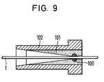
- the art shown in Fig. 9 still has the following problems, although it solves problems of corrosion by using a ceramic material for the support member 101.
- the ceramic material is sintered to cover the die guide with ceramic as shown in Fig. 6(b)
- the ceramic material must be sintered at 1000°C to 1500°C.
- US-A-4 613 740 describes an improved guide holder for an electrodischarge machining apparatus having a wire electrode, characterized in that the guide holder has a guide member with a cap, preferably non-conductive, fixed to one side of a diamond body having a hole for passing through the wire electrode and a pedestal fixed to the other side of the diamond body and that the cap and the pedestal each have a truncated conical hole which is in communication with the hole of the diamond body.
- a guide for a travelling wire comprising: a die guide having a hole for insertion of the wire; a support member surrounding said die guide; and at least one collar having a generally conical interior contour and a hole for passage of said wire, and made of a corrosion resistant electrical insulating material, said at least one collar being located at least on a wire inlet-side of said die guide as an aid in the insertion of said wire and having its smaller diameter end facing said die guide, characterized in that an inside diameter of that portion of the wire inlet-side collar adjacent the die guide is slightly smaller than that of that portion of the die guide adjacent the wire inlet-side collar.
- the inner diameter of that portion of the outlet-side collar which abuts the die guide may be slightly larger than that of the portion of the die guide abutting that collar. Furthermore, the inner wall area of a portion of the collar abutting the die guide is straightened.
- the wire guides of the present invention employ an electrical insulating material such as ceramic for the collars which act as wire electrode guides, to prevent the guide surface profile from changing and the surface roughness from deteriorating due to electrochemical corrosion. Further, the die guides and collars can be manufactured easily because they may be made by different processes and then combined and tightened.
- the inner diameter of the portion of the wire inlet-side collar abutting the die guide is slightly smaller than that of the portion of the die guide abutting the collar, and the inner diameter of the portion of the wire outlet side collar abutting the die guide may be slightly larger than that of the portion of the die guide abutting the collar, so that when the wire guide is made by combining the die guide with collars manufactured by different processes, the wire electrode may be smoothly guided.
- the collar can be used over long periods without producing a reverse step in the insertion direction. Further, by straightening the inner wall area of the portion of the collar abutting the die guide, dimensional management of the collar may be facilitated, and the collars, even if made of slightly fragile ceramic, will not crack easily during manufacture or use.
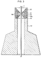
- 1 indicates a wire electrode, 100 a die guide, 101 a support member, 102 a case, and 103 a collar made of ceramic.
- Numeral 100 indicates a die guide made of an extremely hard material such as diamond, sapphire, etc .; 101, a support member similar to the one in the prior art, surrounding the die guide 100 and composed of a sintered powdered metal; and 103 a collar made of ceramic and having a conical guide surface which gradually decreases in diameter toward the die guide 100.
- Numeral 102 indicates a metallic support or casing which contains the die guide 100, support member 101 and collar 103.
- the die guide 100 and the support member 101 are manufactured by processes similar to those of the prior art and fixed to the case 102 by brazing, bonding with epoxy resin adhesive, etc.
- the collar 103 is separately formed by sintering alumina, silicon nitride or other ceramics having electrical insulating properties, using a mold, or by turning ceramic of low hardness and having electrical insulating properties.
- the collar is then secured to the case 102 by bonding with epoxy resin adhesive, etc . or by caulking to the case 102.
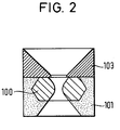
- the collar 103, the die guide 100 and the support member 101 may all be bonded with epoxy adhesive, etc . Since the collar 103 and the die guide 100 are machined in different processes and then combined, there cannot be guaranteed a continuous curve at their abutment due to dimensional variations. As shown in Fig.
- the minimum diameter at the die guide side of the collar slightly smaller in dimension (diameter difference: 0.1 mm or less) than the maximum opening diameter of the die guide introducing portion so that there will be no reverse step in the insertion direction.
- providing a straight area (0.5mm or less) on the die guide side of the collar instead of a sharp edge allows easier dimensional management and makes slightly fragile ceramic more difficult to crack during manufacture and use. Since the collar is made of ceramic that has electrical insulating properties and chemical corrosion resistance as described above, the wire guide is not subjected to electrical or chemical corrosion, the profile and surface roughness of the conical guide surface remain unchanged over a long period, the wire electrode can be inserted smoothly, and the wire guide can be manufactured easily.
- the collar 103 located on the inlet side of the wire electrode may also be located on the outlet side as shown in Fig. 3 so as not to expose the support member and thereby prevent the die guide from dropping due to corrosion of the support member on the outlet side.
- the ceramic material used for the entire collar 103 in the pictured embodiment may be used only on the guide surface itself and still allow the primary purpose to be achieved. That is, a conical sleeve formed of a ceramic material may be fitted into a support member made of a WC-CO material on the like for use as a guide surface for the wire electrode.
- the ceramic material used for the collar may be replaced with other materials having characteristics equivalent to the ceramic.
- the present invention is readily applicable to the guiding wire guides which introduce the wire electrode into its insertion path or to the pressing wire guides 6 and 10, shown in Fig. 4, for pressing the wire electrode against the power supply elements or energizers which supply EDMing power, as well as to the pair of die guides used at the top and bottom of the workpiece.
- the invention is also applicable broadly outside of the EDM area, in any situation where a wire guide may be desirable.
- the EDM environment of the preferred embodiment is an exemplar only, and not a limitation on the invention.
- the invention provides collars made of ceramic, etc . at least on the inlet side of the die guides so as to prevent the occurrence of a reverse step and deterioration of the surface roughness resulting from profile changes influenced by electrical or chemical corrosion of the conical guide surface, to allow smooth and reliable insertion of the wire electrode, especially in the case of insertion by means of an automatic wire electrode supplier.
- the wire guides may be manufactured easily at low cost because they can be made by combining die guides and collars manufactured by different processes.
Landscapes
- Chemical & Material Sciences (AREA)
- Chemical Kinetics & Catalysis (AREA)
- Electrochemistry (AREA)
- Engineering & Computer Science (AREA)
- Mechanical Engineering (AREA)
- Electrical Discharge Machining, Electrochemical Machining, And Combined Machining (AREA)
Claims (12)
- Guide pour fil mobile, comprenant :- un guide de filière (100) ayant un trou pour l'insertion du fil;- un élément de support (101) entourant ledit guide de filière (100); et au moins une bague (103) ayant un contour intérieur généralement conique et un trou pour le passage dudit fil, et constitué d'un matériau électriquement isolant et résistant à la corrosion, ladite au moins une bague (103) étant située au moins sur le côté entrée du fil dudit guide de filière (100) comme aide à l'insertion dudit fil et ayant son côté de plus petit diamètre en regard dudit guide de filière (100),
caractérisé en ce que :- le diamètre intérieur de la partie de la bague (103) du côté entrée du fil contiguë au guide de filière (100) est légèrement plus petit que celui de la partie du guide de filière (100) contiguë à la bague (103) du côté entrée du fil. - Dispositif selon la revendication 1,
caractérisé en ce que :- le diamètre intérieur de la partie de la bague (103) du côté entrée du fil est de 0,1 mm ou moins inférieur à celui de la partie du guide de filière (100) contiguë à la bague (103) du côté entrée du fil. - Dispositif selon la revendication 1, comprenant en outre :- une bague (103) du côté sortie du fil et dans lequel le diamètre intérieur de la partie de la bague (103) du côté sortie du fil contiguë au guide de filière (100) est légèrement plus grand que celui de la partie du guide de filière (100) contiguë à ladite bague (103) du côté sortie du fil.
- Dispositif selon les revendications 1 et 3, dans lequel la zone de la paroi intérieure de la partie de la bague contiguë audit guide de filière est linéaire.
- Dispositif selon la revendication 1, dans lequel ladite bague est en matériau céramique.
- Dispositif selon la revendication 1, dans lequel ledit élément de support (101) est en métal fritté.
- Dispositif selon la revendication 3, dans lequel ledit élément de support (101) est protégé de la périphérie intérieure dudit guide par ledit guide de filière (100) et lesdites bagues (103) des côtés entrée et sortie.
- Dispositif selon la revendication 1, dans lequel ladite bague (103) du côté entrée du fil est formée comme un élément rapporté monté dans ledit élément de support (101).
- Dispositif selon la revendication 1, comprenant en outre un boîtier (102) pour renfermer ledit élément de support (101), ladite au moins une bague (103) et ledit guide de filière (100), au moins ledit élément de support (101) étant fixé audit boîtier.
- Dispositif selon la revendication 9, dans lequel ladite au moins une bague (103) est fixée audit boîtier (102).
- Dispositif selon la revendication 1, dans lequel ladite au moins une bague (103) est formée séparément dudit élément de support (101) et ensuite combinée avec lui pour former ledit guide.
- Procédé de fabrication d'un guide de fil mobile selon l'une quelconque des revendications précédentes, comprenant les étapes consistant à :1) former et usiner un guide de fil fini (100) et son élément de support fini (101);2) lier ledit guide de fil (100) et ledit élément de support (101) à un boîtier (102) pour ledit guide de fil mobile;3) former et usiner au moins une bague finie (103) ayant un contour intérieur généralement conique et un trou pour le passage d'un fil, à partir d'un matériau électriquement isolant et résistant à la corrosion; et4) assembler ladite bague (103) dans ledit boîtier (102) du côté entrée de fil dudit guide de fil et lier ladite bague à celui-ci.
Applications Claiming Priority (2)
| Application Number | Priority Date | Filing Date | Title |
|---|---|---|---|
| JP275176/89 | 1989-10-23 | ||
| JP1275176A JPH0749173B2 (ja) | 1989-10-23 | 1989-10-23 | ワイヤ放電加工装置のワイヤガイド |
Publications (2)
| Publication Number | Publication Date |
|---|---|
| EP0424603A1 EP0424603A1 (fr) | 1991-05-02 |
| EP0424603B1 true EP0424603B1 (fr) | 1993-12-01 |
Family
ID=17551730
Family Applications (1)
| Application Number | Title | Priority Date | Filing Date |
|---|---|---|---|
| EP90109903A Expired - Lifetime EP0424603B1 (fr) | 1989-10-23 | 1990-05-23 | Guide-fil pour machine du type à fil mobile |
Country Status (4)
| Country | Link |
|---|---|
| US (1) | US5086202A (fr) |
| EP (1) | EP0424603B1 (fr) |
| JP (1) | JPH0749173B2 (fr) |
| DE (1) | DE69004931T2 (fr) |
Families Citing this family (7)
| Publication number | Priority date | Publication date | Assignee | Title |
|---|---|---|---|---|
| EP0519557A1 (fr) * | 1991-06-20 | 1992-12-23 | Koninklijke Philips Electronics N.V. | Guide-fil destiné à être utilisé dans un dispositif à fil d'étincelage |
| DE19548001A1 (de) * | 1995-12-21 | 1997-06-26 | Daimler Benz Ag | Verfahren und Vorrichtung zur Führung wenigstens eines Drahtes in einem mikromechanischen Bauelement |
| DE20120252U1 (de) * | 2001-01-25 | 2002-05-23 | Siemens AG, 80333 München | Elektrodenführung für Erodiermaschinen |
| US6624376B1 (en) | 2002-05-21 | 2003-09-23 | Tech Mold, Inc. | Wire guide for electric discharge machine |
| CA2653730A1 (fr) * | 2006-06-30 | 2008-01-03 | Mcmaster University | Procede d'usinage par decharge electrique par fil assiste par abrasion |
| JP4928184B2 (ja) * | 2006-07-21 | 2012-05-09 | 株式会社ソディック | ワイヤ位置決め装置 |
| CN117139759B (zh) * | 2023-10-31 | 2024-01-23 | 赫比(成都)精密塑胶制品有限公司 | 多段异形锥形孔的加工方法及工件 |
Family Cites Families (11)
| Publication number | Priority date | Publication date | Assignee | Title |
|---|---|---|---|---|
| JPS563148A (en) * | 1979-06-22 | 1981-01-13 | Mitsubishi Electric Corp | Wire cut electric discharge machine |
| JPS57121420A (en) * | 1981-01-12 | 1982-07-28 | Mitsubishi Electric Corp | Cutting oil splash prevention device for wire-cut spark erosion machine |
| CH662299A5 (de) * | 1982-02-05 | 1987-09-30 | Ogura Jewel Industry Co Ltd | Fuehrungshalter fuer eine bearbeitungsmaschine mittels elektroentladung mit einer drahtelektrode. |
| JPS61121830A (ja) * | 1984-11-16 | 1986-06-09 | Mitsubishi Electric Corp | ワイヤ放電加工装置 |
| JPH0227902Y2 (fr) * | 1985-06-25 | 1990-07-26 | ||
| JPS6218348U (fr) * | 1985-07-18 | 1987-02-03 | ||
| JPS632627A (ja) * | 1986-06-18 | 1988-01-07 | Mitsubishi Electric Corp | ワイヤ放電加工装置 |
| DE3715844A1 (de) * | 1986-06-18 | 1987-12-23 | Mitsubishi Electric Corp | Funkenerosionsmaschine mit drahtelektrode |
| JPS63193623A (ja) * | 1987-02-05 | 1988-08-10 | Iwatsu Electric Co Ltd | 不正使用防止機能を有する携帯電話方式 |
| JPS63207524A (ja) * | 1987-02-20 | 1988-08-26 | Toshiba Corp | 放電加工機のワイヤ−ガイド |
| JP2624521B2 (ja) * | 1988-08-18 | 1997-06-25 | オグラ宝石精機工業株式会社 | 放電加工機の電極ガイド装置 |
-
1989
- 1989-10-23 JP JP1275176A patent/JPH0749173B2/ja not_active Expired - Lifetime
-
1990
- 1990-05-23 EP EP90109903A patent/EP0424603B1/fr not_active Expired - Lifetime
- 1990-05-23 DE DE90109903T patent/DE69004931T2/de not_active Expired - Lifetime
- 1990-07-30 US US07/559,800 patent/US5086202A/en not_active Expired - Lifetime
Also Published As
| Publication number | Publication date |
|---|---|
| JPH0749173B2 (ja) | 1995-05-31 |
| EP0424603A1 (fr) | 1991-05-02 |
| DE69004931D1 (de) | 1994-01-13 |
| US5086202A (en) | 1992-02-04 |
| DE69004931T2 (de) | 1994-05-05 |
| JPH03136724A (ja) | 1991-06-11 |
Similar Documents
| Publication | Publication Date | Title |
|---|---|---|
| US6225589B1 (en) | Electric discharge machining apparatus | |
| Masuzawa et al. | A combined electrical machining process for micronozzle fabrication | |
| US20100012628A1 (en) | Abrasion assisted wire electrical discharge machining process | |
| US5345057A (en) | Method of cutting an aperture in a device by means of a laser beam | |
| EP1009574B2 (fr) | Fil-electrode destine a etre utilise en usinage par etincelage et son procede de preparation | |
| EP0424603B1 (fr) | Guide-fil pour machine du type à fil mobile | |
| Fuller | Electrical discharge machining | |
| Moulton | Wire EDM the fundamentals | |
| JP2010221391A (ja) | 放電加工装置の電極ガイドおよびこれを用いた放電加工装置 | |
| US6711802B2 (en) | Method of manufacturing multi-core ferrule | |
| JP2001512055A (ja) | 放電加工用の遊動カバー電極ガイドシステム | |
| US3467593A (en) | Electrochemical deburring under pressure | |
| JPH0460768B2 (fr) | ||
| EP1779952A2 (fr) | Gabarit pour rectifier des électrodes. | |
| JP3884210B2 (ja) | ワイヤ電極による加工方法及び装置 | |
| Singh et al. | Wire electrical discharge machining process | |
| KR100432098B1 (ko) | 공작물을 0.1φ로 천공하기 위한 슈퍼드릴 셋팅 방법 | |
| JPH0553566B2 (fr) | ||
| Kar et al. | Prospects of Micromachining using Electrical Discharge Machining | |
| SU1060383A1 (ru) | Способ электроэрозионного изготовлени рабочих элементов вырубных штампов | |
| WO1983001403A1 (fr) | Procede et machine de formation d'une matrice | |
| JP2000084746A (ja) | 微細切削方法および微細切削装置 | |
| JP2001129727A (ja) | 細深穴部材または細深穴金型の製作方法 | |
| US4436975A (en) | Wire-cut, electric discharge machining method | |
| EP3766618A1 (fr) | Cathode pour usinage électrochimique avec optimisation des paramètres d'écoulement |
Legal Events
| Date | Code | Title | Description |
|---|---|---|---|
| PUAI | Public reference made under article 153(3) epc to a published international application that has entered the european phase |
Free format text: ORIGINAL CODE: 0009012 |
|
| 17P | Request for examination filed |
Effective date: 19901220 |
|
| AK | Designated contracting states |
Kind code of ref document: A1 Designated state(s): CH DE LI |
|
| 17Q | First examination report despatched |
Effective date: 19920813 |
|
| GRAA | (expected) grant |
Free format text: ORIGINAL CODE: 0009210 |
|
| AK | Designated contracting states |
Kind code of ref document: B1 Designated state(s): CH DE LI |
|
| REF | Corresponds to: |
Ref document number: 69004931 Country of ref document: DE Date of ref document: 19940113 |
|
| PLBE | No opposition filed within time limit |
Free format text: ORIGINAL CODE: 0009261 |
|
| STAA | Information on the status of an ep patent application or granted ep patent |
Free format text: STATUS: NO OPPOSITION FILED WITHIN TIME LIMIT |
|
| 26N | No opposition filed | ||
| PGFP | Annual fee paid to national office [announced via postgrant information from national office to epo] |
Ref country code: CH Payment date: 20080527 Year of fee payment: 19 |
|
| PGFP | Annual fee paid to national office [announced via postgrant information from national office to epo] |
Ref country code: DE Payment date: 20090527 Year of fee payment: 20 |
|
| REG | Reference to a national code |
Ref country code: CH Ref legal event code: PL |
|
| PG25 | Lapsed in a contracting state [announced via postgrant information from national office to epo] |
Ref country code: LI Free format text: LAPSE BECAUSE OF NON-PAYMENT OF DUE FEES Effective date: 20090531 Ref country code: CH Free format text: LAPSE BECAUSE OF NON-PAYMENT OF DUE FEES Effective date: 20090531 |
|
| PG25 | Lapsed in a contracting state [announced via postgrant information from national office to epo] |
Ref country code: DE Free format text: LAPSE BECAUSE OF EXPIRATION OF PROTECTION Effective date: 20100523 |