EP0424607A2 - Méthode pour distinguer des queues de pouls de stimulation - Google Patents
Méthode pour distinguer des queues de pouls de stimulation Download PDFInfo
- Publication number
- EP0424607A2 EP0424607A2 EP90110300A EP90110300A EP0424607A2 EP 0424607 A2 EP0424607 A2 EP 0424607A2 EP 90110300 A EP90110300 A EP 90110300A EP 90110300 A EP90110300 A EP 90110300A EP 0424607 A2 EP0424607 A2 EP 0424607A2
- Authority
- EP
- European Patent Office
- Prior art keywords
- pace pulse
- signal
- detected signal
- peak
- tail
- Prior art date
- Legal status (The legal status is an assumption and is not a legal conclusion. Google has not performed a legal analysis and makes no representation as to the accuracy of the status listed.)
- Granted
Links
Images



Classifications
-
- A—HUMAN NECESSITIES
- A61—MEDICAL OR VETERINARY SCIENCE; HYGIENE
- A61B—DIAGNOSIS; SURGERY; IDENTIFICATION
- A61B5/00—Measuring for diagnostic purposes; Identification of persons
- A61B5/72—Signal processing specially adapted for physiological signals or for diagnostic purposes
- A61B5/7203—Signal processing specially adapted for physiological signals or for diagnostic purposes for noise prevention, reduction or removal
- A61B5/7217—Signal processing specially adapted for physiological signals or for diagnostic purposes for noise prevention, reduction or removal of noise originating from a therapeutic or surgical apparatus, e.g. from a pacemaker
-
- A—HUMAN NECESSITIES
- A61—MEDICAL OR VETERINARY SCIENCE; HYGIENE
- A61B—DIAGNOSIS; SURGERY; IDENTIFICATION
- A61B5/00—Measuring for diagnostic purposes; Identification of persons
- A61B5/24—Detecting, measuring or recording bioelectric or biomagnetic signals of the body or parts thereof
- A61B5/316—Modalities, i.e. specific diagnostic methods
- A61B5/318—Heart-related electrical modalities, e.g. electrocardiography [ECG]
- A61B5/346—Analysis of electrocardiograms
- A61B5/349—Detecting specific parameters of the electrocardiograph cycle
- A61B5/366—Detecting abnormal QRS complex, e.g. widening
Definitions
- Electrocardiogram (ECG) monitoring device an important feature is the detection and characterization of each individual heart beat present in the ECG signal. This information is then used to generate both heart rate information and alarms in life threatening situations.
- Monitoring an ECG signal from a patient having a pacemaker is difficult as pace pulses generated by the pacemaker can occur at any time. When they occur between QRS complexes they can be incorrectly detected by a QRS detector and result in an incorrect high heart rate measurement. When they occur during a QRS complex, they can cause incorrect feature measurement and result in an erroneous QRS classification.
- the detection of asystole is necessary to alert nurses of the cessation of heart activity which is indicated by the absence of the QRS complex in the ECG signal.
- the ECG signal even after asystole, contains periodically occurring pace pulses, which may resemble heart activity. The presence of pace pulses on an ECG signal makes it difficult to detect such asystole conditions.
- a typical pace pulse consists of two components, a main pulse and a repolarization pulse.
- the main pulse which is used to stimulate the heart, is characterized by its narrow width, sharp rise and fall, and large variation in amplitude.
- the actual shape of the pace pulse depends on the output coupling design of the pacemaker.
- the repolarization pulse sometimes referred to as a pace pulse tail, is used to deplete the capacitive coupling generated by the delivery of the pace pulse charge built up between the heart and the pacemaker.
- the shape and size of the pace pulse tail is a function of the energy content of the pace pulse and the amount of capacitive coupling.
- bandpass filtering in the monitoring equipment may create a "pace pulse tail".
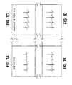
- FIGS 1A and 1B Two examples of pace pulse signals recorded on the surface ECG are shown in Figures 1A and 1B.
- Figure 1A is a pace pulse with a small repolarization tail
- Figure 1B illustrates a large repolarization tail generated by the pacemaker system.
- Figures 1C, and 1D both pace pulse signals exhibit significant repolarization tails after bandpass filtering.
- pace pulse signals In order to more accurately monitor ECG signals it has been found helpful to eliminate pace pulse signals. Such elimination requires that the pace pulse first be identified.
- the process of identifying pace pulses may employ the technique disclosed in U.S. Patent No. 4,664,116 and incorporated by reference; wherein, pace pulses are identified by the existence of high frequency "spikes" having narrow width and a sharp rise time which exceeds a minimum dynamic noise threshold.
- FIG. 3 shows pace pulse signals with the pace pulse tail
- Figure 2B illustrates the pace pulse tail after the pace pulse spike has been removed using the above mentioned technique.
- the remaining energy of the pace pulse tail may be erroneously detected as a QRS complex. This may cause the misdiagnosis of the patient's underlying ECG rhythm and result in a missed detection of an asystole condition.
- this invention to provide a method for differentiating pace pulse tails from true QRS complexes in an ECG signal waveforms.
- a method is described by which a paced ECG signal can be analyzed to discriminate pace pulse tails from QRS complexes.
- Pace pulse tails tend to have an exponential decay which is due to the capacitive discharge of the impulse energy delivered by the pace pulse.
- normal QRS complexes generated by heart muscle contraction do not contain any exponentially decaying segments.
- a pace pulse detector can be employed to locate pace pulse signals and a QRS detector, which compares the ECG signal amplitude to a dynamic threshold can be employed to locate potential QRS complexes. By comparing the relative locations of the pace pulse and the potential QRS complex, a determination can be made as to whether the signal is likely to be a pace pulse tail. If it is, additional analysis must be undertaken before the signal can be discriminated as a pace pulse tail.
- the invention discriminates pace pulse tails as those signals which follow a pace pulse signal and have an exponential decay.
- an exponentially decaying signal can be identified by calculating the ratio of the instantaneous slope to the amplitude at a series of samples along the signal following the peak of the pace pulse tail. If this ratio is approximately a constant for a predetermined time duration, then the signal must decay exponentially.
- the invention further includes a technique for estimating the asymptote of the pace pulse tail.
- An initial baseline is estimated as the point preceding the peak of the pace pulse tail which has the minimum slope.
- An additional correction term may also be employed for compensating for the amount of undershoot of the pace pulse tail due to the averaging effect of the high pass filter. From this estimated asymptote, it is possible to get more realistic amplitude measurements.
- a threshold region above and below the asymptote may be employed to assist in the identification of the pace pulse tail.
- this region several cases that are uncharacteristic of an exponentially decaying waveform can be defined which will not be identified as a pace pulse tail. They are: 1) signals that enter this region too close to the peak, 2) signals that enter this region and subsequently exit the region, and 3) signals that cross through this region.
- the presence of 50/60 Hz power line noise may also effect the accuracy of the amplitude and slope measurements.
- the invention further comprises a technique for detecting and eliminating this noise. If the number of times that the difference of several consecutive samples change sign exceeds a predetermined threshold, it is possible to determine the presence of 50/60 Hz noise in the ECG signal.
- the 50/60 Hz noise may be removed by averaging the signal over several consecutive samples.
- another technique can be used to identify exponentially decaying signals by matching the ECG signal to two known exponentially decaying curves.
- the time constant of the curves can be an average time constant for known pace pulse tails.
- the peak of each curve is offset from the peak of the signal by a constant.
- pace pulse tails generated by pace pulse signals are discriminated from true QRS complexes by mathematically ascertaining if the signal following the pace pulse peak has an exponential decay. Additionally, several other criteria indicative of pace pulse tails may be used to identify a signal as having an exponential decay.
- the description of the preferred embodiment begins by representing an exponentially decaying waveform both graphically and algebraically. From a mathematical equation, it is possible to illustrate the inventive technique for determining whether the waveform decays exponentially. Additional factors such as variations in the waveform baseline, the concept of a threshold region and 50/60 Hz noise detection and elimination are illustrated both graphically and algebraically.
- the method and apparatus of the preferred embodiment are disclosed, in particular, the general operation of the pace pulse tail peak detector, the asymptote estimator, threshold computation and 50/60 Hz detection and removal.
- the description of the preferred embodiment concludes with a description of the method for discriminating pace pulse tails.
- FIG. 5 illustrates a pace pulse and the corresponding exponentially decaying waveform V having an amplitude A and a time constant T.
- This waveform is also represented by Equation 1.0.
- the derivative, or instantaneous rate of change of the waveform yields the same exponentially decaying wave but attenuated by the negative time constant T, as shown in Equation 2.0.
- the ratio of the derivative of the signal V to itself results in a negative constant which is equivalent to the time constant of the exponential decaying waveform as shown in Equation 3.0.
- Equation 3.0 The relationship shown in Equation 3.0 is employed in this invention to identify the presence of a pace pulse tail.
- V A exp[-Tt] (1.0)
- FIG. 6 A more accurate representation of the pace pulse is depicted in Figure 6, in which two additional components, B and C are shown.
- the parameter B represents the baseline offset not removed by the highpass filter.
- the parameter C represents the asymptote or the final resting point of the exponentially decaying waveform. This undershoot of the exponential waveform is due to the averaging effect of the highpass filter from the large pace pulse spike.
- the exponential decaying waveform shown in Figure 6 can be modeled by Equation 4.0.
- the derivative of V is a function of the time constant T, offset C and V as given in Equation 5.0.
- Equation 3.0 The ratio of the derivative of the signal to itself given in Equation 6.0 is no longer a simple negative constant as shown in Equation 3.0.
- the offset C In order to utilize the relationship given in Equation 3.0 for pace pulse tail discrimination, the offset C must be estimated.
- V (A + B + C) exp[-Tt] - C (4.0)
- Figure 7 illustrates how the asymptote can be estimated.
- an initial baseline estimate B ⁇ is determined by locating the point t B with the minimum slope within a predefined search window.
- the search window located immediately prior to the peak of the pace pulse tail at t R is 80 msec wide, which is 10 data samples at a sampling rate of 125 samples per second.
- the final asymptote estimate ⁇ as shown in Equation 9.0 is the sum of the initial baseline estimate plus a correction term.
- B ⁇ V(tB) - 1/8[V(t PEAK ) - V(t B )] (9.0)
- the correction term is used to estimate the amount of undershoot of the exponential waveform. This ensures that the baseline is correctly positioned relative to the asymptote of the exponential wave.
- a correction value of one-eighth of the adjusted peak amplitude which is the difference of the peak amplitude V(t PEAK ) and the initial baseline estimate V(t B ), has been empirically determined to provide the most accurate estimate.
- Figure 8 illustrates the construction of a threshold region around the asymptote of the pace pulse tail. This region which is centered around the asymptote is bounded between ⁇ +Delta and ⁇ -Delta.
- the threshold Delta is computed in Equation 10.0 and is illustrated in Figure 9.
- the value of Delta is between a minimum value of 8 and a maximum value of 64, both of which are empirically determined. Within these limits the value of Delta is directly proportional to the adjusted peak amplitude of the pace pulse tail.
- DELTA MIN ⁇ 64, MAX[3/32 [V(t PEAK ) - ⁇ ], 8 ⁇ (10.0)
- Equation 11.0 A exp [-Tt] + F sin (wt) (11.0)
- dV/dt TA exp [-Tt] + Fw cos (wt) (12.0)
- (dV/dt)/V -T + (F/V) [T sin (wt) + w cos (wc)] (13.0)
- the block diagram of Figure 11 illustrates the inventive method for discriminating pace pulse tails.
- the corresponding pace pulse signal is first located.
- pace pulse signal does not have to be removed, pace pulse tail discrimination can be enhanced by such removal.
- a band pass filter 10 is employed to eliminate unwanted signals due to baseline wander and high frequency muscle artifacts.
- An A/D converter 20 is used to digitize and sample the filtered ECG signal at a rate of 500 samples per second. While the band pass filter removes unwanted signals, it may also generate exponentially decaying tails due to pace pulses.
- a pace pulse detector 30 and another A/D converter 40 which are employed to locate the pace pulse and to generate a corresponding enable signal 45 which is employed to synchronize a pace pulse eliminator 50.
- the pace pulse eliminator 50 described in U.S. Patent No.
- 4,832,041 receives the filtered and digitized ECG signal and eliminates the pace pulse.
- the elimination of the pace pulse results in a gap being formed which is "filled" by approximating a line where the pace pulse used to be.
- a QRS detector 60 is coupled to the output of the pace pulse eliminator 50 for detecting the presence of QRS complexes after pace pulses have been removed.
- the ECG samples used by the QRS detector is 125 samples per second.
- the present invention is embodied in the pace pulse tail rejector 70 which is coupled to the output of both the A/D converter 40 and the QRS detector 60.
- the input to the pace pulse tail rejector 70 is the ECG waveform from the pace pulse eliminator.
- the pace pulse detector 30 provides an enable signal which indicates the presence of a pace pulse.
- the general operation of the pace pulse tail rejector 70 is shown functionally in the block diagram illustrated in Figure 11. The following flowcharts correspond to each block in the diagram; Figure 12 - Pacer Tail Peak Detector, Figure 13 - Asymptote Estimator, Figure 14 - Threshold Computation, Figures 15 and 16- 50/60 Hz Noise Detector and Filter, and Figure 17 - Pace Pulse Tail identification.
- the first step in ascertaining whether the output of the QRS Detector 60 is a pace pulse tail is illustrated in Figure 11 where a determination must be made to see if the signal is preceded by a pace pulse (D1). If there is no pace pulse within a predetermined distance of the potential QRS complex, then this signal cannot be identified as a pace pulse tail.
- the peak of the pace pulse tail is located (F12) using the technique set forth in Figure 12.
- a signal maximum (Vmax) and a signal minimum (Vmin) are determined over a predetermined period (at 26,28 and D3), and if Vmax is greater than 3/4 times Vmin, then Vmax is the peak of the pace pulse tail (at D8 and 34), or if Vmin is greater than 3/4 times Vmax, then Vmin is the peak of the pace pulse tail (at D9 and 32). If Tmax equal Tmin, then no peaks are found.
- the next step in the process as set forth in the block diagram of Figure 11, is to make an asymptote estimation (F13).
- a threshold region is established on either side of the estimated asymptote.
- the manner in which the decaying signal enters and possibly crosses through this region is important to how it is classified. For example, if an ECG signal enters the threshold region too rapidly, or if it enters and comes out again or if it enters and passes right through, then the signal will not be identified as a pace pulse tail as this is not characteristic of an exponentially decaying signal which continually approaches the asymptote.
- the threshold computation is made after the asymptote estimation and prior to the identification of the pace pulse tail.
- the presence of noise may effect the ability of the invention to accurately discriminate pace pulse tails.
- 50/60 Hz noise has been found to cause erroneous slope measurements.
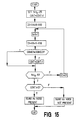
- the flowchart of Figure 15 highlights how this noise may be detected.
- the differences of consecutive samples of the ECG signal approximately 200 milliseconds to 40 milliseconds preceding the detector peak are compared. The number of times that these differences change sign are counted and used as an estimate of the number of noise cycles contained in the window. If the number of cycles is greater than 5 in a 160 millisecond window, then 50/60 cycle noise is present.
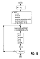
- the flowchart of Figure 16 highlights how this noise may be removed.
- a filtering "window" of four consecutive points is utilized to compute the average amplitude of the series of samples. Once a value has been determined, the window is shifted by one, and four amplitude values in the window are averaged providing a second averaged amplitude value. This process is continued for 25 samples, and then the process is repeated a second time to ensure that the 50/60 Hz noise is removed.
- the preferred method for ascertaining whether a signal has an exponential decay is set forth in the flowchart Figure 17.
- ratios of the instantaneous slope to the amplitude of a series of ECG signal samples are computed.
- An exponential waveform is identified when this ratio for each sample is the same. It should be noted that no single constant can be selected to represent all types of pace pulse tails, therefore, any ratio that falls within a small predetermined range of negative values will be associated with an exponentially decaying waveform.
- Ratios having a positive value indicate a departure from the exponential waveform shape unless they occur within a short period from the start of the window, or if the ECG signal is near the asymptote at which point it is very susceptible to noise.
- the preferred embodiment employs a search window of 35 samples following the peak of the exponential waveform to determine if the ECG signal decays exponentially.
- events may occur which are not characteristic of an exponentially decaying waveform and obviate the need for such an analysis.
- the ECG signal amplitude is less than the threshold value within 10 samples of the waveform peak (at D30, "N ⁇ Tpeak + 10"), then the ECG signal can not be identified as a pace pulse tail as it has "decayed" faster than a typical exponentially decaying waveform.
Landscapes
- Health & Medical Sciences (AREA)
- Life Sciences & Earth Sciences (AREA)
- Engineering & Computer Science (AREA)
- Signal Processing (AREA)
- Cardiology (AREA)
- Surgery (AREA)
- Molecular Biology (AREA)
- Physics & Mathematics (AREA)
- Veterinary Medicine (AREA)
- Biophysics (AREA)
- Pathology (AREA)
- Biomedical Technology (AREA)
- Heart & Thoracic Surgery (AREA)
- Medical Informatics (AREA)
- Public Health (AREA)
- General Health & Medical Sciences (AREA)
- Animal Behavior & Ethology (AREA)
- Computer Vision & Pattern Recognition (AREA)
- Psychiatry (AREA)
- Physiology (AREA)
- Artificial Intelligence (AREA)
- Measurement And Recording Of Electrical Phenomena And Electrical Characteristics Of The Living Body (AREA)
- Electrotherapy Devices (AREA)
Applications Claiming Priority (2)
| Application Number | Priority Date | Filing Date | Title |
|---|---|---|---|
| US07/426,338 US5033473A (en) | 1989-10-24 | 1989-10-24 | Method for discriminating pace pulse tails |
| US426338 | 1989-10-24 |
Publications (3)
| Publication Number | Publication Date |
|---|---|
| EP0424607A2 true EP0424607A2 (fr) | 1991-05-02 |
| EP0424607A3 EP0424607A3 (en) | 1992-03-04 |
| EP0424607B1 EP0424607B1 (fr) | 1995-04-26 |
Family
ID=23690377
Family Applications (1)
| Application Number | Title | Priority Date | Filing Date |
|---|---|---|---|
| EP90110300A Expired - Lifetime EP0424607B1 (fr) | 1989-10-24 | 1990-05-30 | Méthode pour distinguer des queues de pouls de stimulation |
Country Status (4)
| Country | Link |
|---|---|
| US (1) | US5033473A (fr) |
| EP (1) | EP0424607B1 (fr) |
| JP (1) | JP2995080B2 (fr) |
| DE (1) | DE69018924T2 (fr) |
Cited By (6)
| Publication number | Priority date | Publication date | Assignee | Title |
|---|---|---|---|---|
| EP0634134A1 (fr) * | 1993-07-16 | 1995-01-18 | Siemens-Elema AB | Méthode et dispositif pour augmenter SNR dans des signaux d'ECG |
| EP0850593A3 (fr) * | 1996-12-19 | 1998-10-28 | Siemens Medical Systems, Inc. | Procédé et appareil pour le comptage précis de battements cardiaques stimulés |
| EP0826392A3 (fr) * | 1996-08-29 | 1998-12-09 | Pacesetter AB | Procédé et appareil adaptatifs d'extraction d'une composante de réponse provoquée à partir d'un signal cardiaque mesuré, en supprimant les composantes de polarisation d'électrode |
| CN110477906A (zh) * | 2019-08-26 | 2019-11-22 | 电子科技大学 | 一种心电信号qrs波起止点定位方法 |
| EP4154807A1 (fr) * | 2021-09-22 | 2023-03-29 | Nihon Kohden Corporation | Appareil de traitement d'informations physiologiques, procédé et programme de traitement d'informations physiologiques |
| EP4497387A1 (fr) * | 2023-07-25 | 2025-01-29 | Biosense Webster (Israel) Ltd. | Filtrage d'électrogrammes intracardiaques en présence de pointes de stimulation |
Families Citing this family (15)
| Publication number | Priority date | Publication date | Assignee | Title |
|---|---|---|---|---|
| US5443485A (en) * | 1993-09-08 | 1995-08-22 | Intermedics, Inc. | Apparatus and method for capture detection in a cardiac stimulator |
| US5431693A (en) * | 1993-12-10 | 1995-07-11 | Intermedics, Inc. | Method of verifying capture of the heart by a pacemaker |
| US5660184A (en) * | 1995-05-15 | 1997-08-26 | Johnson & Johnson Medical, Inc. | Pacemaker pulse detection and artifact rejection |
| US5682902A (en) * | 1995-10-16 | 1997-11-04 | Hewlett-Packard Company | ECG pace pulse detection and processing |
| US5913828A (en) * | 1996-10-29 | 1999-06-22 | Hewlett-Packard Company | Method and apparatus for distinguishing pacing pulses in an EKG using conduction velocity calculations |
| US5951483A (en) * | 1998-01-26 | 1999-09-14 | Physio-Control Manufacturing Corporation | Method and apparatus for detecting an internal pacemaker pulse |
| US6363278B1 (en) * | 2000-04-14 | 2002-03-26 | Cardiac Pacemakers, Inc. | Cardiac rhythm management system with staggered pulses for coordination therapy |
| DE10250996A1 (de) * | 2002-10-30 | 2004-05-13 | Biotronik Meß- und Therapiegeräte GmbH & Co. Ingenieurbüro Berlin | Stimulationsvorrichtung mit Stimulationserfolgskontrolle |
| US7191004B2 (en) * | 2002-12-31 | 2007-03-13 | Cardiac Pacemakers, Inc. | Capture verification using an evoked response reference |
| US7162301B2 (en) * | 2002-12-31 | 2007-01-09 | Cardiac Pacemakers, Inc. | Method and system for detecting capture with cancellation of pacing artifact |
| JP6140403B2 (ja) * | 2012-07-30 | 2017-05-31 | フクダ電子株式会社 | 心臓刺激検査システム及び心臓刺激検査システムの作動方法 |
| US9435694B2 (en) * | 2013-03-14 | 2016-09-06 | Kelsey-Hayes Company | Outside air temperature measurement device and method |
| US10485439B2 (en) * | 2017-11-30 | 2019-11-26 | Biosense Webster (Isreal) Ltd. | Fast recovery of ECG signal method and apparatus |
| US11607181B2 (en) * | 2018-07-20 | 2023-03-21 | GE Precision Healthcare LLC | Systems and methods for cardiac triggering of an imaging system |
| CN114366121B (zh) * | 2022-01-18 | 2024-04-19 | 西安理工大学 | 基于数字形态学的双动态阈值心电qrs波检测方法 |
Family Cites Families (9)
| Publication number | Priority date | Publication date | Assignee | Title |
|---|---|---|---|---|
| US4105023A (en) * | 1977-01-19 | 1978-08-08 | American Optical Corporation | Pacemaker artifact suppression in coronary monitoring |
| FR2533432A1 (fr) * | 1982-09-23 | 1984-03-30 | Europ Propulsion | Procede et dispositif de detection de la reponse du coeur a une impulsion electrique de stimulation |
| US4585001A (en) * | 1982-09-28 | 1986-04-29 | Norland Corporation | Cardiac pacer signal detector |
| US4585004A (en) * | 1984-06-01 | 1986-04-29 | Cardiac Control Systems, Inc. | Heart pacing and intracardiac electrogram monitoring system and associated method |
| US4791936A (en) * | 1985-02-15 | 1988-12-20 | Siemens-Pacesetter, Inc. | Apparatus for interpreting and displaying cardiac events of a heart connected to a cardiac pacing means |
| US4832041A (en) * | 1987-02-26 | 1989-05-23 | Hewlett-Packard Company | Pace pulse eliminator |
| US4887609A (en) * | 1987-05-13 | 1989-12-19 | The Methodist Hospital System | Apparatus and method for filtering electrocardiograph signals |
| US4893632A (en) * | 1988-04-13 | 1990-01-16 | Siemens Aktiengesellschaft | Method and apparatus for comparing waveform shapes of time-varying signals |
| EP0356573B1 (fr) * | 1988-09-02 | 1994-12-07 | Nihon Kohden Corporation | Dispositif de surveillance de stimulation du coeur |
-
1989
- 1989-10-24 US US07/426,338 patent/US5033473A/en not_active Expired - Lifetime
-
1990
- 1990-05-30 EP EP90110300A patent/EP0424607B1/fr not_active Expired - Lifetime
- 1990-05-30 DE DE69018924T patent/DE69018924T2/de not_active Expired - Lifetime
- 1990-10-24 JP JP2288261A patent/JP2995080B2/ja not_active Expired - Fee Related
Cited By (7)
| Publication number | Priority date | Publication date | Assignee | Title |
|---|---|---|---|---|
| EP0634134A1 (fr) * | 1993-07-16 | 1995-01-18 | Siemens-Elema AB | Méthode et dispositif pour augmenter SNR dans des signaux d'ECG |
| US5564428A (en) * | 1993-07-16 | 1996-10-15 | Siemens-Elema Ab | Method and apparatus for enhancing the signal-to-noise ratio of ECG signals |
| EP0826392A3 (fr) * | 1996-08-29 | 1998-12-09 | Pacesetter AB | Procédé et appareil adaptatifs d'extraction d'une composante de réponse provoquée à partir d'un signal cardiaque mesuré, en supprimant les composantes de polarisation d'électrode |
| EP0850593A3 (fr) * | 1996-12-19 | 1998-10-28 | Siemens Medical Systems, Inc. | Procédé et appareil pour le comptage précis de battements cardiaques stimulés |
| CN110477906A (zh) * | 2019-08-26 | 2019-11-22 | 电子科技大学 | 一种心电信号qrs波起止点定位方法 |
| EP4154807A1 (fr) * | 2021-09-22 | 2023-03-29 | Nihon Kohden Corporation | Appareil de traitement d'informations physiologiques, procédé et programme de traitement d'informations physiologiques |
| EP4497387A1 (fr) * | 2023-07-25 | 2025-01-29 | Biosense Webster (Israel) Ltd. | Filtrage d'électrogrammes intracardiaques en présence de pointes de stimulation |
Also Published As
| Publication number | Publication date |
|---|---|
| EP0424607A3 (en) | 1992-03-04 |
| DE69018924D1 (de) | 1995-06-01 |
| US5033473A (en) | 1991-07-23 |
| JPH03151934A (ja) | 1991-06-28 |
| EP0424607B1 (fr) | 1995-04-26 |
| JP2995080B2 (ja) | 1999-12-27 |
| DE69018924T2 (de) | 1995-12-21 |
Similar Documents
| Publication | Publication Date | Title |
|---|---|---|
| EP0424607B1 (fr) | Méthode pour distinguer des queues de pouls de stimulation | |
| US4296755A (en) | Method and apparatus for determining ventricular fibrillation | |
| EP0198087B1 (fr) | Detecteur d'artefacts dans la mesure de signaux emis par un corps vivant | |
| US8112147B2 (en) | Method and apparatus for generating determination indexes for identifying ECG interfering signals | |
| US6477404B1 (en) | System and method for detection of pacing pulses within ECG signals | |
| EP1094323B1 (fr) | Procédé et appareil pour identifier la cause d'une décharge partielle | |
| US7383079B2 (en) | Nonlinear method and apparatus for electrocardiogram pacemaker signal filtering | |
| EP0850593B1 (fr) | Appareil pour le comptage précis de battements cardiaques stimulés | |
| US4919144A (en) | Defibrillator ECG interpreter | |
| US5660184A (en) | Pacemaker pulse detection and artifact rejection | |
| WO1998009241A1 (fr) | Appareil et procede de detection d'un depart, decalage ou crete d'une onde p-qrs-t dans un ecg | |
| JPS5867235A (ja) | 心拍数を測定する方法及び装置 | |
| SE437762B (sv) | Sett att detektera med avstand upptredande, varandra liknande signaler i en signalblandning | |
| EP0280529B1 (fr) | Appareil d'électrocardiographie | |
| EP0101545A2 (fr) | Procédé et dispositif d'évaluation du taux des battements cardiaques | |
| US4453551A (en) | Apparatus for pattern recognition of ECG signals for detecting fibrillation | |
| US4237903A (en) | QRS detector for EKG signals | |
| US5961468A (en) | Detection of the heart response of pacemaker patients | |
| EP0634136B1 (fr) | Méthode et dispositif pour traiter des signaux d'ECG | |
| Kannathal et al. | Analysis of electrocardiograms | |
| GB2070871A (en) | Pattern recognition | |
| Falzett et al. | A method for determining threshold from single-unit neural activity | |
| Lall et al. | Performance challenges in ECG pacemaker pulse detection systems | |
| Van Den Akker et al. | An on-line method for reliable detection of waveforms and subsequent estimation of events in physiological signals | |
| Kejariwal | A QRS detection algorithm for discriminating artifacts in ECG records |
Legal Events
| Date | Code | Title | Description |
|---|---|---|---|
| PUAI | Public reference made under article 153(3) epc to a published international application that has entered the european phase |
Free format text: ORIGINAL CODE: 0009012 |
|
| AK | Designated contracting states |
Kind code of ref document: A2 Designated state(s): DE FR GB |
|
| PUAL | Search report despatched |
Free format text: ORIGINAL CODE: 0009013 |
|
| AK | Designated contracting states |
Kind code of ref document: A3 Designated state(s): DE FR GB |
|
| 17P | Request for examination filed |
Effective date: 19920326 |
|
| 17Q | First examination report despatched |
Effective date: 19940802 |
|
| GRAA | (expected) grant |
Free format text: ORIGINAL CODE: 0009210 |
|
| AK | Designated contracting states |
Kind code of ref document: B1 Designated state(s): DE FR GB |
|
| PG25 | Lapsed in a contracting state [announced via postgrant information from national office to epo] |
Ref country code: FR Effective date: 19950426 |
|
| REF | Corresponds to: |
Ref document number: 69018924 Country of ref document: DE Date of ref document: 19950601 |
|
| EN | Fr: translation not filed | ||
| PLBE | No opposition filed within time limit |
Free format text: ORIGINAL CODE: 0009261 |
|
| STAA | Information on the status of an ep patent application or granted ep patent |
Free format text: STATUS: NO OPPOSITION FILED WITHIN TIME LIMIT |
|
| 26N | No opposition filed | ||
| PGFP | Annual fee paid to national office [announced via postgrant information from national office to epo] |
Ref country code: GB Payment date: 19980427 Year of fee payment: 9 |
|
| PG25 | Lapsed in a contracting state [announced via postgrant information from national office to epo] |
Ref country code: GB Free format text: LAPSE BECAUSE OF NON-PAYMENT OF DUE FEES Effective date: 19990530 |
|
| GBPC | Gb: european patent ceased through non-payment of renewal fee |
Effective date: 19990530 |
|
| PGFP | Annual fee paid to national office [announced via postgrant information from national office to epo] |
Ref country code: DE Payment date: 20090720 Year of fee payment: 20 |
|
| PG25 | Lapsed in a contracting state [announced via postgrant information from national office to epo] |
Ref country code: DE Free format text: LAPSE BECAUSE OF EXPIRATION OF PROTECTION Effective date: 20100530 |