EP0424671A2 - Appareil pour créer un écoulement à déplacement avec faible turbulence - Google Patents
Appareil pour créer un écoulement à déplacement avec faible turbulence Download PDFInfo
- Publication number
- EP0424671A2 EP0424671A2 EP90118110A EP90118110A EP0424671A2 EP 0424671 A2 EP0424671 A2 EP 0424671A2 EP 90118110 A EP90118110 A EP 90118110A EP 90118110 A EP90118110 A EP 90118110A EP 0424671 A2 EP0424671 A2 EP 0424671A2
- Authority
- EP
- European Patent Office
- Prior art keywords
- annular space
- space
- core tube
- annular
- outlet opening
- Prior art date
- Legal status (The legal status is an assumption and is not a legal conclusion. Google has not performed a legal analysis and makes no representation as to the accuracy of the status listed.)
- Granted
Links
- 238000006073 displacement reaction Methods 0.000 title claims abstract description 13
- 230000002950 deficient Effects 0.000 title 1
- 239000002184 metal Substances 0.000 claims description 3
- 238000007493 shaping process Methods 0.000 claims 1
- 239000003570 air Substances 0.000 description 72
- 239000003973 paint Substances 0.000 description 6
- 238000010422 painting Methods 0.000 description 4
- 238000001035 drying Methods 0.000 description 3
- 230000006698 induction Effects 0.000 description 3
- 230000035515 penetration Effects 0.000 description 3
- 239000000443 aerosol Substances 0.000 description 2
- 239000012080 ambient air Substances 0.000 description 2
- 238000001816 cooling Methods 0.000 description 2
- 238000010438 heat treatment Methods 0.000 description 2
- 239000002904 solvent Substances 0.000 description 2
- 230000005540 biological transmission Effects 0.000 description 1
- 230000015572 biosynthetic process Effects 0.000 description 1
- 239000003344 environmental pollutant Substances 0.000 description 1
- 238000011010 flushing procedure Methods 0.000 description 1
- 239000000203 mixture Substances 0.000 description 1
- 238000007591 painting process Methods 0.000 description 1
- 239000002245 particle Substances 0.000 description 1
- 231100000719 pollutant Toxicity 0.000 description 1
- 230000001360 synchronised effect Effects 0.000 description 1
- 238000009423 ventilation Methods 0.000 description 1
Images



Classifications
-
- F—MECHANICAL ENGINEERING; LIGHTING; HEATING; WEAPONS; BLASTING
- F24—HEATING; RANGES; VENTILATING
- F24F—AIR-CONDITIONING; AIR-HUMIDIFICATION; VENTILATION; USE OF AIR CURRENTS FOR SCREENING
- F24F13/00—Details common to, or for air-conditioning, air-humidification, ventilation or use of air currents for screening
- F24F13/02—Ducting arrangements
- F24F13/06—Outlets for directing or distributing air into rooms or spaces, e.g. ceiling air diffuser
- F24F13/068—Outlets for directing or distributing air into rooms or spaces, e.g. ceiling air diffuser formed as perforated walls, ceilings or floors
Definitions
- the invention relates to a device for generating a low-turbulence displacement flow with a distributor space which is connected to an air supply line via a supply nozzle and is provided with outlet openings on the base side.
- Such a device known from DE 36 43 175 A1, has a distribution space, the outlet openings of which are defined by the holes in a perforated plate forming the bottom of the storage space.
- the outlet openings open into a chamber which is arranged under the distributor space and which is provided on the bottom side with nozzles serving as outlet openings.
- the center distance of the nozzles from each other corresponds at least to 3 to 12 times the outlet diameter of the nozzles.
- the individual jets that can be generated with this device are not completely free of turbulence, but they allow the formation of a stable displacement flow with a relatively low air volume flow.
- a major disadvantage of the known device is that it cannot be used to form a sufficiently stable low-turbulence displacement flow in rooms with great heights.
- the supply air In aircraft painting halls, the supply air must be blown out from great heights, whereby the discharge height can be 20-25 m. In such halls, the exhaust air is extracted through floor ducts, so that the air flow is directed vertically from top to bottom. To solvent vapors, paint aerosols u. Like. To displace as direct as possible turbulence to the exhaust air ducts, the air flow must be low in turbulence. The pollutants should not mix too intensively with the air in the room and should only remain in the hall for a relatively short time. High concentrations of paint aerosols and solvents in the air affect both the health of the personnel and the quality of the surfaces to be painted on an aircraft.
- the painting process is followed by drying of the sprayed-on paint. While the painting is carried out at temperatures of approx. 20-22 ° C and the supply air is blown in more or less isothermally or slightly supercooled, the supply air temperature is increased during drying in order to accelerate the drying process. The supply air temperature is higher than the room air temperature. The same condition occurs during painting in the winter months when the transmission losses have to be covered by the ventilation.
- the jet pulse must therefore be varied depending on the temperature difference between the room and supply air.
- the outlet pulse of the supply air jets must be higher than in the cooling case, in which the supply air is colder than the room air.
- the beam pulse must also be adapted to the type of aircraft to be painted. Aircrafts with a larger fuselage height are better washed by fresh air than those with a lower fuselage height. This already results from the different distance from the blow-out plane of the device for introducing the supply air into the hall.
- a corresponding part of the air volume flow is directed vertically downwards and tears it Supply air jets, which exit through the perforated plates via the annular space, thereby extending the penetration depth of the entire supply air accordingly.
- the part of the air volume flow that flows vertically downwards is mainly chosen to be large if the supply air is warmer than the room air.
- the preferably circular annular outlet opening which forms the air jet apron can be closed by an annular disk which is coupled to the valve plate closing the core tube and is kept synchronously adjustable in height within the distribution space.
- a further embodiment of the invention provides that the group of outlet openings arranged in a circle around the upper opening cross section of the core tube or the annular outlet opening can be closed by an annular disk which is likewise coupled to the valve disk but is kept synchronously adjustable in height within the annular space.
- either the flow paths bypassing the annular space can be increasingly closed by a lifting movement of the valve plate, while the flow path leading over the annular space is increasingly opened, or else the flow paths surrounding the annular space are increasingly opened, while the flow paths leading over the annular space are increasingly closed.
- the annular space bounded on the outside by perforated sheets and surrounding the core tube is delimited by a cylindrical outer jacket and a circular disk-shaped bottom, the diameter of the bottom being smaller than the diameter of the outer jacket and connected to the bottom by a truncated cone-shaped jacket piece is.
- This configuration of the device enables a fanned out, low-turbulence air flow of the supply air jets to be achieved.
- a further embodiment of the invention provides for the annular space to be covered by a perforated sheet metal ring arranged at a distance from the underside of the distributor space.
- a further embodiment of the invention provides for a perforated plate disk to be arranged in the distributor space at a distance parallel to the outlet cross section of the feed nozzle, the diameter of which being larger than the diameter of the feed nozzle. Thereby The entire air volume flow passes through this perforated plate, divided into individual jets, into the distribution room.
- each device 1 from three devices arranged in the ceiling area of a hall, supply air from a height of 20-25 m, based on the level of the hall floor, is blown into the direction of the arrow as a displacement flow and extracted from the hall in the direction of the arrow via floor inlets (not shown).
- each device 1 forms a row of devices with further devices, not shown, which are arranged at intervals, so that the entire hall space, but at least the object to be acted on, for example an airplane, can be acted upon by the displacement flow.
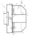
- each of the devices 1 consists of a distribution space 2 which is circular in plan and which is provided on the ceiling side with a concentrically arranged, vertically oriented feed support 3.
- the supply nozzle 3 can be connected to an air supply line, not shown.
- the distributor space 2 is provided with an outlet opening 4, which is also arranged concentrically and is defined by the upper opening cross section of a core tube 5, which is aligned coaxially with the feed connector 3 and points downward from the distributor space 2.
- the outlet opening 4 can be completely or partially shut off by a valve plate 7 arranged inside the distributor space 2 and height-adjustable with the aid of a drive motor 6.
- the distributor space is also provided on the bottom and concentrically around the outlet opening 4 at a radial distance from it with an annular outlet opening 8 which can be shut off by an annular disk 9 which is coupled to the valve disk 7 via a linkage 10.
- annular disk 9 is arranged outside the distributor space 2 below its bottom side, a closing movement of the valve plate 7 causes an opening movement of the ring disk 9 and an opening movement of the valve plate 7 causes a closing movement of the ring disk 9.
- the distributor space 2 is again on the bottom side and concentric with the outlet opening 4 at a radial distance from the outlet opening 8 further annular outlet opening 11, which is arranged in the edge region of the distributor space 2 and can be shut off by an annular disk 12, which in turn is coupled to the valve plate 7 via the linkage 10 and, like the valve plate 7, is mounted inside the distributor space 2.
- annular disk 12 can be moved synchronously with the valve disk 7 into the closed or open position, whereas the annular disk 9, despite synchronous movement in the same direction as the valve disk 7 and the annular disk 12, assumes opposite positions, provided the valve disk 7 and the annular disks 9 and 12 are not are in a middle position.
- a perforated plate 13 is arranged on the ceiling side above the mouth area of the feed connector 3 at a distance parallel to the cross-section of the mouth. The volume flow flowing into the distribution space is evened out with the perforated plate.
- annular space 14 is connected to the underside of the distribution space 2 and, depending on the opening state of the outlet opening 8, is connected to the distribution space 2. While the inner wall of the annular space 14 is defined by the core tube 5, a cylindrical outer jacket 15, a frustoconical jacket piece 16 connected to its lower edge and a circular disk-shaped member connected to its lower edge define Bottom 17 the annular space 14.
- the cylindrical outer jacket 15, the frustoconical jacket piece 16 and the circular disk-shaped bottom 17 are made of perforated sheets.
- the circular disk-shaped base 17 also extends over the lower outlet cross section of the core tube 5 and forms a perforated closure for this.
- the distributor space 2 projects radially beyond the annular space 14 in such a way that the outlet opening 11 opens outside the annular space 14 and the part of the volume flow emerging via the outlet opening 11 forms an air jet apron enveloping the annular space 14 and thus bypasses the annular space 14 as well as the one passed through the core tube 5 Part of the volume flow.
- the air jets emerging through the holes in the walls of the annular space 14 are directed more or less intensely vertically downward into the hall space to be supplied with supply air and form an overall low-turbulence displacement flow.
- the inner diameter d of the core tube 5 should 0.1-0.4 times and the height h of the cylindrical part of the annular space should correspond to 0.15-0.25 times the outer diameter D of the annular space.
- the circular bottom of the annular space 14 should have a diameter D 1, which corresponds to 0.6-0.7 times the outer diameter D of the annular space, and the width s by which the base area of the distributor space 2 protrudes radially beyond the annular space 14 should be so large be dimensioned so that it corresponds to 0.02-0.04 times the outer diameter D of the annular space 14.
- the truncated cone-shaped jacket piece 16 of the annular space 14 should have an angle of inclination to the horizontal of 40-50 °.
- FIG. 5 a shows, with the outlet opening 4 closed and the outlet opening 11 also closed, the entire supply air flows into the annular space 14 via the outlet opening 8 and from there via the perforated plates delimiting the annular space 14 into the space. This creates low-turbulence fanned air jets with a low exit impulse. This position is selected when the supply air is colder than the room air.
- the outlet opening 4 and the outlet opening 11 are partially open, so that part of the supply air flows as a supporting jet with a higher air speed over the core tube 5 and the outlet opening 11 and the large-area air flow from the perforated sheet casing of the Annulus 14 induced.
- the depth of penetration increases because the total air supplied is fanned out less. This position is preferably chosen if the supply air temperature does not differ significantly from the hall temperature.
- valve disk 7 and the annular disk 12 are raised further from the outlet opening 4 and the outlet opening 11 compared to the illustration in FIG. 5b, as a result of which the supporting jet is intensified, the exit impulse is increased and the depth of penetration is lengthened.
- This position is preferably chosen when the supply air is warmer than the room air.
- the exit speed of the support jet which exits through the core tube 5 is in the range of 0 -20 m / s adjustable. The higher the exit speed, the higher the induction.
- the core tube 5 is arranged in the center of the outlet and the air jet from the outlet opening 11 affects the cylindrical jacket of the annular space 14, the supporting jet does not induce the ambient air, but predominantly the adjacent supply air jets which emerge via the perforated sheet metal jacket.
- the perforated sheet sheathing also has the advantage that the incoming air jets have a low-turbulence characteristic, the smaller the hole diameter, the smaller the turbulence.
- a low-turbulence displacement flow is achieved with very little induction of the room air.
- paint particles released in a paint shop can thus be displaced very intensively in the direction of the floor and sucked off through floor inlets.
Landscapes
- Engineering & Computer Science (AREA)
- Chemical & Material Sciences (AREA)
- Combustion & Propulsion (AREA)
- Mechanical Engineering (AREA)
- General Engineering & Computer Science (AREA)
- Duct Arrangements (AREA)
- Air-Flow Control Members (AREA)
- Aeration Devices For Treatment Of Activated Polluted Sludge (AREA)
- Paper (AREA)
Priority Applications (1)
| Application Number | Priority Date | Filing Date | Title |
|---|---|---|---|
| AT90118110T ATE85417T1 (de) | 1989-10-26 | 1990-09-20 | Vorrichtung zur erzeugung einer turbulenzarmen verdraengungsstroemung. |
Applications Claiming Priority (2)
| Application Number | Priority Date | Filing Date | Title |
|---|---|---|---|
| DE3935620A DE3935620C2 (de) | 1989-10-26 | 1989-10-26 | Vorrichtung zum Einbringen einer turbulenzarmen Verdrängungsströmung |
| DE3935620 | 1989-10-26 |
Publications (3)
| Publication Number | Publication Date |
|---|---|
| EP0424671A2 true EP0424671A2 (fr) | 1991-05-02 |
| EP0424671A3 EP0424671A3 (en) | 1991-09-04 |
| EP0424671B1 EP0424671B1 (fr) | 1993-02-03 |
Family
ID=6392230
Family Applications (1)
| Application Number | Title | Priority Date | Filing Date |
|---|---|---|---|
| EP90118110A Expired - Lifetime EP0424671B1 (fr) | 1989-10-26 | 1990-09-20 | Appareil pour créer un écoulement à déplacement avec faible turbulence |
Country Status (5)
| Country | Link |
|---|---|
| US (1) | US5069114A (fr) |
| EP (1) | EP0424671B1 (fr) |
| AT (1) | ATE85417T1 (fr) |
| DE (2) | DE3935620C2 (fr) |
| ES (1) | ES2038473T3 (fr) |
Cited By (3)
| Publication number | Priority date | Publication date | Assignee | Title |
|---|---|---|---|---|
| EP0541977A3 (en) * | 1991-11-11 | 1993-10-27 | Krantz H Gmbh & Co | Device for creating a displacement-flow with poor turbulence |
| EP0634614A1 (fr) * | 1993-07-17 | 1995-01-18 | Schako Metallwarenfabrik Ferdinand Schad KG | Sortie d'air |
| CN107965859A (zh) * | 2017-10-13 | 2018-04-27 | 浙江理工大学 | 一种两路均分新风诱导干盘管空调装置 |
Families Citing this family (16)
| Publication number | Priority date | Publication date | Assignee | Title |
|---|---|---|---|---|
| CA2071680C (fr) * | 1992-06-19 | 1998-05-05 | Walter D. Klassen | Diffuseur a ecoulement radial |
| DE4432303C2 (de) * | 1994-09-10 | 1998-01-15 | Krantz Tkt Gmbh | Luftzuführvorrichtung |
| US5938525A (en) * | 1997-07-23 | 1999-08-17 | Tompkins Industries, Inc | Air diffuser, and mold and method for its production |
| DE19753888C1 (de) * | 1997-12-05 | 1999-02-25 | Krantz Tkt Gmbh | Verdrängungsluftauslaß |
| US6361432B1 (en) | 1999-08-17 | 2002-03-26 | Tomkins Industries, Inc. | Air diffuser with air flow regulator |
| US7641125B2 (en) * | 2005-04-29 | 2010-01-05 | E.H. Price Ltd. | Variable air volume ceiling diffuser |
| KR20070064907A (ko) * | 2005-12-19 | 2007-06-22 | 삼성전자주식회사 | 공기조화기 |
| US7841087B1 (en) | 2007-02-23 | 2010-11-30 | Walker Jr Mark S | Connector for use with inflatable tubing |
| US8468716B1 (en) | 2007-10-23 | 2013-06-25 | Mary A. Walker | Pressurized drying system |
| US20090264062A1 (en) * | 2008-04-16 | 2009-10-22 | Nuclimate Air Quality Systems, Inc. | Ventilation system |
| US8911286B1 (en) * | 2010-01-05 | 2014-12-16 | Michael Lee Savigny | Concentric air diffuser with an angled supply air face |
| NZ631243A (en) * | 2014-09-08 | 2015-11-27 | Fusion Hvac Pty Ltd | Diffuser module |
| US10871304B2 (en) | 2016-11-07 | 2020-12-22 | Air Distribution Technologies Ip, Llc | Air diffuser |
| US11752838B2 (en) * | 2019-04-22 | 2023-09-12 | Air Distribution Technologies Ip, Llc | Variable flow adapters for air diffusers of HVAC systems |
| US11187431B2 (en) * | 2019-04-22 | 2021-11-30 | Air Distribution Technologies Ip, Llc | Variable flow adapters for air diffusers with damper |
| EP4092337B1 (fr) * | 2020-01-19 | 2025-04-23 | GD Midea Air-Conditioning Equipment Co., Ltd. | Unité intérieure de climatisation et climatiseur |
Family Cites Families (11)
| Publication number | Priority date | Publication date | Assignee | Title |
|---|---|---|---|---|
| DE2033195C3 (de) * | 1970-07-04 | 1981-04-16 | LTG Luftechnische GmbH, 7000 Stuttgart | Luftaustrittseinrichtung für Klimaanlagen |
| DE2718760A1 (de) * | 1977-04-27 | 1978-11-02 | Mabag Luft & Klimatechnik | Luftauslass fuer lueftungs- und/oder klimatisierungssysteme |
| DE3042216C2 (de) * | 1980-11-08 | 1986-03-27 | H. Krantz Gmbh & Co, 5100 Aachen | Drallauslaß |
| GB2120778A (en) * | 1982-05-20 | 1983-12-07 | Howorth Air Eng Ltd | Outlet device for an air conditioning system |
| JPS5989947A (ja) * | 1982-11-11 | 1984-05-24 | Toyo Maruchibento Kk | 空調用吹出口装置 |
| DE3435602A1 (de) * | 1984-09-28 | 1986-07-10 | Ferdinand Schad KG, 7201 Kolbingen | Vorrichtung zur zufuehrung von luft in raeume |
| DE3600821A1 (de) * | 1985-01-15 | 1986-07-17 | Tiepoldt, Dieter R., 4190 Kleve | Vorrichtung zum ausblasen von zuluft zur belueftung von industriehallen oder dergleichen |
| DE3731375A1 (de) * | 1986-10-09 | 1988-04-21 | Jakob Adam | Klimaanlage mit quelluftauslass |
| DE3643175A1 (de) * | 1986-12-18 | 1988-06-30 | Krantz H Gmbh & Co | Vorrichtung zur erzeugung einer verdraengungsstroemung |
| SU1446427A2 (ru) * | 1987-04-27 | 1988-12-23 | Н.Я.Кириленко | Устройство дл подачи и распределени воздуха |
| DE8903028U1 (de) * | 1989-03-13 | 1989-05-11 | Gebrüder Trox, GmbH, 4133 Neukirchen-Vluyn | Deckenluftauslaß für Lüftungs- und Klimaanlagen |
-
1989
- 1989-10-26 DE DE3935620A patent/DE3935620C2/de not_active Expired - Fee Related
-
1990
- 1990-09-20 EP EP90118110A patent/EP0424671B1/fr not_active Expired - Lifetime
- 1990-09-20 ES ES199090118110T patent/ES2038473T3/es not_active Expired - Lifetime
- 1990-09-20 AT AT90118110T patent/ATE85417T1/de not_active IP Right Cessation
- 1990-09-20 DE DE9090118110T patent/DE59000840D1/de not_active Expired - Fee Related
- 1990-10-19 US US07/600,518 patent/US5069114A/en not_active Expired - Fee Related
Cited By (3)
| Publication number | Priority date | Publication date | Assignee | Title |
|---|---|---|---|---|
| EP0541977A3 (en) * | 1991-11-11 | 1993-10-27 | Krantz H Gmbh & Co | Device for creating a displacement-flow with poor turbulence |
| EP0634614A1 (fr) * | 1993-07-17 | 1995-01-18 | Schako Metallwarenfabrik Ferdinand Schad KG | Sortie d'air |
| CN107965859A (zh) * | 2017-10-13 | 2018-04-27 | 浙江理工大学 | 一种两路均分新风诱导干盘管空调装置 |
Also Published As
| Publication number | Publication date |
|---|---|
| DE59000840D1 (de) | 1993-03-18 |
| EP0424671A3 (en) | 1991-09-04 |
| ES2038473T3 (es) | 1993-07-16 |
| EP0424671B1 (fr) | 1993-02-03 |
| DE3935620A1 (de) | 1991-05-02 |
| ATE85417T1 (de) | 1993-02-15 |
| US5069114A (en) | 1991-12-03 |
| DE3935620C2 (de) | 1995-04-20 |
Similar Documents
| Publication | Publication Date | Title |
|---|---|---|
| EP0424671B1 (fr) | Appareil pour créer un écoulement à déplacement avec faible turbulence | |
| DE69014765T2 (de) | Verfahren zum Bilden einer von einem Luftstrom umspülten Zone. | |
| DE4127608B4 (de) | Lufteinlaß | |
| DE3740714A1 (de) | Luftstromverteiler | |
| DE1207559B (de) | Verfahren und Vorrichtung zum Herstellen von kugelfoermigen Partikeln aus Glas oder anderen glasartigen Stoffen | |
| DE3810482C2 (fr) | ||
| DE3939063C2 (fr) | ||
| DE2710723A1 (de) | Dreidimensionaler spruehzerstaeubungsturm | |
| CH653430A5 (de) | Drallauslass mit einem aussenrohr und einem darin koaxial angeordneten kernrohr. | |
| DE2833822C2 (de) | Decken-Luftauslaßvorrichtung für variablen Volumenstrom zur Raumbelüftung | |
| DE3600821A1 (de) | Vorrichtung zum ausblasen von zuluft zur belueftung von industriehallen oder dergleichen | |
| DE4317733A1 (de) | Verfahren zum Einstellen der Zufuhr eines einem Schmelzofen zuzuführenden Reaktionsgases und ein Vielzweckbrenner zur Durchführung des Verfahrens | |
| DE2138539B2 (de) | Luftauslasseinrichtung | |
| DE2608252C2 (de) | Klimaleuchte | |
| DE1534429C3 (fr) | ||
| CH648923A5 (en) | Swirl outlet from an outer pipe and a core pipe arranged concentrically therein | |
| DE10015666A1 (de) | Verfahren und Einrichtung zum Erfassen, Trennen und Absaugen von fluiden Medien unter Verwendung von Frontalwirbelgeneratoren | |
| DE3429710C2 (fr) | ||
| DE3826690A1 (de) | Zerstaeubungsverfahren fuer fluessigkeiten | |
| DE4124850C2 (de) | Luftauslaß für Lüftungs- und Klimaanlagen | |
| DE4010134A1 (de) | Luftzufuehrungsvorrichtung fuer die raumklimatisierung | |
| DE3329641C2 (fr) | ||
| DE1604114C (de) | Einrichtung zur Aufrechterhaltung einer staub und bakterienfreien Zone in nerhalb eines Raumes | |
| DE2106186C3 (de) | Fußbodenluftauslaß fur Klimaanlagen | |
| DE4213982C1 (en) | Ceiling or wall air outlet with air feed pipe - which has internal nozzle tube, forming annular gap and radial air distributor with collar-like adjusting ring |
Legal Events
| Date | Code | Title | Description |
|---|---|---|---|
| PUAI | Public reference made under article 153(3) epc to a published international application that has entered the european phase |
Free format text: ORIGINAL CODE: 0009012 |
|
| 17P | Request for examination filed |
Effective date: 19901231 |
|
| AK | Designated contracting states |
Kind code of ref document: A2 Designated state(s): AT BE CH DE ES FR GB IT LI NL |
|
| PUAL | Search report despatched |
Free format text: ORIGINAL CODE: 0009013 |
|
| AK | Designated contracting states |
Kind code of ref document: A3 Designated state(s): AT BE CH DE ES FR GB IT LI NL |
|
| 17Q | First examination report despatched |
Effective date: 19920518 |
|
| GRAA | (expected) grant |
Free format text: ORIGINAL CODE: 0009210 |
|
| AK | Designated contracting states |
Kind code of ref document: B1 Designated state(s): AT BE CH DE ES FR GB IT LI NL |
|
| REF | Corresponds to: |
Ref document number: 85417 Country of ref document: AT Date of ref document: 19930215 Kind code of ref document: T |
|
| REF | Corresponds to: |
Ref document number: 59000840 Country of ref document: DE Date of ref document: 19930318 |
|
| GBT | Gb: translation of ep patent filed (gb section 77(6)(a)/1977) |
Effective date: 19930222 |
|
| ET | Fr: translation filed | ||
| ITF | It: translation for a ep patent filed | ||
| PGFP | Annual fee paid to national office [announced via postgrant information from national office to epo] |
Ref country code: FR Payment date: 19930601 Year of fee payment: 4 |
|
| REG | Reference to a national code |
Ref country code: ES Ref legal event code: FG2A Ref document number: 2038473 Country of ref document: ES Kind code of ref document: T3 |
|
| PGFP | Annual fee paid to national office [announced via postgrant information from national office to epo] |
Ref country code: BE Payment date: 19930915 Year of fee payment: 4 |
|
| PLBE | No opposition filed within time limit |
Free format text: ORIGINAL CODE: 0009261 |
|
| STAA | Information on the status of an ep patent application or granted ep patent |
Free format text: STATUS: NO OPPOSITION FILED WITHIN TIME LIMIT |
|
| 26N | No opposition filed | ||
| PG25 | Lapsed in a contracting state [announced via postgrant information from national office to epo] |
Ref country code: BE Effective date: 19940930 |
|
| BERE | Be: lapsed |
Owner name: H. KRANTZ G.M.B.H. & CO. Effective date: 19940930 |
|
| PG25 | Lapsed in a contracting state [announced via postgrant information from national office to epo] |
Ref country code: FR Effective date: 19950531 |
|
| REG | Reference to a national code |
Ref country code: FR Ref legal event code: ST |
|
| PGFP | Annual fee paid to national office [announced via postgrant information from national office to epo] |
Ref country code: ES Payment date: 19950901 Year of fee payment: 6 |
|
| PGFP | Annual fee paid to national office [announced via postgrant information from national office to epo] |
Ref country code: GB Payment date: 19950908 Year of fee payment: 6 |
|
| PG25 | Lapsed in a contracting state [announced via postgrant information from national office to epo] |
Ref country code: GB Effective date: 19960920 |
|
| PG25 | Lapsed in a contracting state [announced via postgrant information from national office to epo] |
Ref country code: ES Free format text: LAPSE BECAUSE OF THE APPLICANT RENOUNCES Effective date: 19960921 |
|
| GBPC | Gb: european patent ceased through non-payment of renewal fee |
Effective date: 19960920 |
|
| REG | Reference to a national code |
Ref country code: ES Ref legal event code: FD2A Effective date: 19991102 |
|
| PGFP | Annual fee paid to national office [announced via postgrant information from national office to epo] |
Ref country code: AT Payment date: 20000914 Year of fee payment: 11 |
|
| PGFP | Annual fee paid to national office [announced via postgrant information from national office to epo] |
Ref country code: NL Payment date: 20000930 Year of fee payment: 11 |
|
| PGFP | Annual fee paid to national office [announced via postgrant information from national office to epo] |
Ref country code: CH Payment date: 20001030 Year of fee payment: 11 |
|
| PG25 | Lapsed in a contracting state [announced via postgrant information from national office to epo] |
Ref country code: AT Free format text: LAPSE BECAUSE OF NON-PAYMENT OF DUE FEES Effective date: 20010920 |
|
| PG25 | Lapsed in a contracting state [announced via postgrant information from national office to epo] |
Ref country code: CH Free format text: LAPSE BECAUSE OF NON-PAYMENT OF DUE FEES Effective date: 20010930 Ref country code: LI Free format text: LAPSE BECAUSE OF NON-PAYMENT OF DUE FEES Effective date: 20010930 |
|
| PG25 | Lapsed in a contracting state [announced via postgrant information from national office to epo] |
Ref country code: NL Free format text: LAPSE BECAUSE OF NON-PAYMENT OF DUE FEES Effective date: 20020401 |
|
| REG | Reference to a national code |
Ref country code: CH Ref legal event code: PL |
|
| NLV4 | Nl: lapsed or anulled due to non-payment of the annual fee |
Effective date: 20020401 |
|
| NLV4 | Nl: lapsed or anulled due to non-payment of the annual fee |
Effective date: 20020401 |
|
| PG25 | Lapsed in a contracting state [announced via postgrant information from national office to epo] |
Ref country code: IT Free format text: LAPSE BECAUSE OF NON-PAYMENT OF DUE FEES;WARNING: LAPSES OF ITALIAN PATENTS WITH EFFECTIVE DATE BEFORE 2007 MAY HAVE OCCURRED AT ANY TIME BEFORE 2007. THE CORRECT EFFECTIVE DATE MAY BE DIFFERENT FROM THE ONE RECORDED. Effective date: 20050920 |
|
| PGFP | Annual fee paid to national office [announced via postgrant information from national office to epo] |
Ref country code: DE Payment date: 20080930 Year of fee payment: 19 |
|
| PG25 | Lapsed in a contracting state [announced via postgrant information from national office to epo] |
Ref country code: DE Free format text: LAPSE BECAUSE OF NON-PAYMENT OF DUE FEES Effective date: 20100401 |