EP0424727B1 - Procédé de production de trifluorure d'azote - Google Patents
Procédé de production de trifluorure d'azote Download PDFInfo
- Publication number
- EP0424727B1 EP0424727B1 EP90119385A EP90119385A EP0424727B1 EP 0424727 B1 EP0424727 B1 EP 0424727B1 EP 90119385 A EP90119385 A EP 90119385A EP 90119385 A EP90119385 A EP 90119385A EP 0424727 B1 EP0424727 B1 EP 0424727B1
- Authority
- EP
- European Patent Office
- Prior art keywords
- anode
- electrolytic cell
- gas
- cathode
- electrolysis
- Prior art date
- Legal status (The legal status is an assumption and is not a legal conclusion. Google has not performed a legal analysis and makes no representation as to the accuracy of the status listed.)
- Expired - Lifetime
Links
Images

Classifications
-
- C—CHEMISTRY; METALLURGY
- C25—ELECTROLYTIC OR ELECTROPHORETIC PROCESSES; APPARATUS THEREFOR
- C25B—ELECTROLYTIC OR ELECTROPHORETIC PROCESSES FOR THE PRODUCTION OF COMPOUNDS OR NON-METALS; APPARATUS THEREFOR
- C25B1/00—Electrolytic production of inorganic compounds or non-metals
- C25B1/01—Products
- C25B1/24—Halogens or compounds thereof
- C25B1/245—Fluorine; Compounds thereof
-
- C—CHEMISTRY; METALLURGY
- C25—ELECTROLYTIC OR ELECTROPHORETIC PROCESSES; APPARATUS THEREFOR
- C25B—ELECTROLYTIC OR ELECTROPHORETIC PROCESSES FOR THE PRODUCTION OF COMPOUNDS OR NON-METALS; APPARATUS THEREFOR
- C25B9/00—Cells or assemblies of cells; Constructional parts of cells; Assemblies of constructional parts, e.g. electrode-diaphragm assemblies; Process-related cell features
- C25B9/09—Fused bath cells
-
- C—CHEMISTRY; METALLURGY
- C25—ELECTROLYTIC OR ELECTROPHORETIC PROCESSES; APPARATUS THEREFOR
- C25B—ELECTROLYTIC OR ELECTROPHORETIC PROCESSES FOR THE PRODUCTION OF COMPOUNDS OR NON-METALS; APPARATUS THEREFOR
- C25B9/00—Cells or assemblies of cells; Constructional parts of cells; Assemblies of constructional parts, e.g. electrode-diaphragm assemblies; Process-related cell features
- C25B9/17—Cells comprising dimensionally-stable non-movable electrodes; Assemblies of constructional parts thereof
Definitions
- This invention relates to a method for producing a nitrogen trifluoride gas by a molten salt electrolysis.
- a nitrogen trifluoride gas is used as a dry etching agent for semiconductors and a cleaning gas for CVD apparatuses. Its demand for these uses has been recently increased. In such applications, a nitrogen trifluoride gas of high purity, in particular, the content of carbon tetrafluoride being low, should be used.
- NF3 gas can be manufactured by various methods. Among them, a molten salt electrolysis gives good yield and is suitable for mass production as compared with other methods and therefore, is regarded as useful commercial processes. In particular, for the purpose of producing a highly pure NF3 gas containing only a small amount of CF4, the molten salt electrolysis method can produce NF3, at the lowest cost and thereby, the method is expected to be an advantageous method.
- exemplary suitable molten salt baths comprise acidic ammonium fluoride, NH4F ⁇ HF systems derived from ammonium fluoride and hydrogen fluoride, or KF ⁇ NH4F ⁇ HF systems produced by adding acidic potassium fluoride or potassium fluoride to the NH4F ⁇ HF system.
- NF3 gas and nitrogen (N2) gas are generated at the anode while hydrogen (H2) gas is generated at the cathode. That is, so-called gas generating reactions occur at the both electrodes.
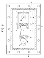
- an electrolytic cell is provided with a partition plate for separating anode and cathode as illustrated in FIGS. 1 and 2.
- a fluororesin for the purpose of inhibiting corrosion of the partition plate and preventing the partition plate from functioning as an electrode, it is usually preferable to use a fluororesin as the partition plate or to cover the partition plate with a fluororesin.
- a carbon (C) or nickel (Ni) electrode can be used, and a nickel electrode is preferably used as an anode so as to obtain a highly pure gas containing less amount of CF4.
- a nickel electrode is used, there is a drawback that nickel is slightly dissolved.
- the present inventors used a nickel anode for a long time. A part of the dissolved nickel precipitated on the cathode, and while the electrolysis was carried out for a long period of time, the distance between the cathode and the partition plate gradually became small.
- the present inventors used the electrodes for a long period of time and found that the anode was getting shorter with the lapse of time and the current density at anode increased. As a result, the amount of NF3 gas generated per unit area of the Ni anode increased and the diffusion of the NF3 gas became more vigorous. As NF3 gas diffused more vigorously, NF3 gas generated at anode and H2 gas generated at cathode were mixed when the distance between the partition plate and the anode was too small, and as mentioned above, there was a fear that a gas mixture within the explosion limits was formed in the cathode region.
- Ni electrodes when Ni electrodes are used, there is a disadvantage that the nickel is slightly dissolved in an electrolytic bath.
- the present inventors used nickel electrodes for a long time, a part of the dissolved nickel deposited in the form of nickel fluoride at the bottom of an electrolytic cell, and while the electrolysis was carried out for a long period of time, the deposit piled on the bottom surface of the electrolytic cell. It was found that as the nickel fluoride deposited on the bottom surface of the electrolytic cell, the distance between the lower end of the electrode plate and the piled matter became small.
- the lower end of an electrode which is nearer to the bottom surface than the other electrode begins first to be gradually buried in the nickel fluoride, and the portion of the electrode thus buried can not function as an electrode any more.
- the area of the electrode capable of functioning as an electrode is decreased and the current density increases resulting in rise of the voltage of electrolytic cell and poor yield. Consequently the short distance between the lower end of electrode and the bottom surface is not desirable.
- the convection in an electrolytic bath in an electrolytic cell has been now found the be such that in an electrolytic bath a flow from the lower part to the upper part occurs at a region where gases near electrodes rise due to gases generated at both electrodes while the portion of the electrolytic bath having risen to the upper part reversely flows downward at a region apart from the electrodes, and this convection serves to remove Joulean heat generated between the two electrodes by electrolysis by external or internal cooling and thereby the temperature distribution in the electrolytic bath in the electrolytic cell can be kept substantially uniform.
- the temperature of a molten salt upon electrolysis according to a method of a molten salt electrolysis is most preferably 100 - 130 °C since the operation is easy, the electroconductivity is good and, in addition, the electric current efficiency is excellent.
- the NH4F ⁇ HF (melting point of 126°C ) evaporated due to the vapor pressure disadvantageously deposits at a portion where the temperature is lower than the electrolytic bath.
- the present inventors tried to use the electrolytic cell continuously for a long period of time while flowing a carrier gas so as to prevent clog of gas outlets, but it was found that NH4F ⁇ HF deposited even on the inlet of the carrier gas and the inlet was also clogged.
- carrier gas inlets and generated gas outlets are clogged as mentioned above, a pressure difference is formed between the anode chamber enclosed with partition plates and containing the gas generated at anode, NF3, and the cathode chamber enclosed with partition plates and containing the gas generated at cathode, H2, and thereby a liquid surface level difference is formed resulting in a cause of big trouble.
- NF3 gas can not be exhausted from the anode chamber and the generation of NF3 gas continues and thereby the pressure in the anode chamber rises.
- the liquid surface in the anode chamber is pushed down while the liquid surface in the cathode chamber is pushed up.
- NF3 gas in the anode chamber enters the cathode chamber to form a gas mixture within explosion limits and thereby the gas mixture is liable to explode in the cathode chamber.
- a method for producing a nitrogen trifluoride gas by a molten salt electrolysis using an electrolytic cell which comprises an anode, a cathode and a partition plate separating the anode and the cathode, the distance between the anode and the partition plate and the distance between the cathode and the partition plate being in the range of 30 to 200 mm.
- the present inventors did a research on the distance between an anode or a cathode and a partition plate separating the anode and the cathode in an electrolytic cell for producing NF3 by a molten salt electrolysis, and have found that NF3 gas can be safely produced for a long period of time by limiting the distance to a certain definite range as mentioned above and have completed the present invention.
- the present invention will be explained in the following by referring to the attached drawing.
- the most important point in this aspect is the distance between an anode or a cathode and a partition plate separating the anode and the cathode in an electrolytic cell for safely producing NF3 for a long period of time.
- lid 3 of the electrolytic cell comprises lid 11 for fixing a partition plate
- lid 11 for fixing a partition plate which is fixed to the main body 1 through packing 14 by bolt and nut 15 for a lid.
- Anode 5 has connecting rod 7a which is through insulating material 8a fitted to lid 11 for fixing partition plate and is fastened by cap nut 9a for fastening a connecting rod.
- Cathode 6 is also connected with connecting rod 7b which is through insulating material 8b fitted to lid 3 and is fastened by cap nut 9b for fixing a connecting rod.
- electrolytic cell main body 1 At the inner bottom surface of electrolytic cell main body 1 is provided fluororesin plate 2, and electrolytic bath 4 is contained in the electrolytic cell.
- the anode chamber is provided with outlet pipe 12 for a gas generated at anode while the cathode chamber is provided with outlet pipe 13 for a gas generated at cathode.
- FIG. 2 reference numbers similar to those in FIG. 1 indicate the parts similar to those in FIG. 1.
- the distance between anode 5 or cathode 6 and partition plate 10 is respectively 30 - 200 mm, preferably 30 - 100 mm.
- a nickel electrode used as an anode is dissolved in the electrolytic bath during the operation for a long period of time and a part of the dissolved nickel deposits on the cathode (e.g. Ni electrode) to grow in the form of protrusion, and thereby the distance between cathode 6 and partition plate 10 is getting shorter.
- H2 gas generated at cathode 6 passes under partition plate 10 and enters the anode chamber, and thereby is mixed with NF3 gas generated at anode 5 resulting in a big problem, that is, the formation of a gas mixture within explosion limits in the anode chamber.
- the size of the electrolytic cell When the distance between cathode 6 and partition plate 10 is longer than 200 mm, the size of the electrolytic cell also becomes larger accordingly resulting in an excess investment.
- the electrolytic bath is so hygroscopic that it inevitably absorbs moisture in air at the stage of preparing the starting materials. Therefore, upon producing NF3, a dehydration electrolysis is essential which is effected by applying an electric current having a current density lower than that upon a main electrolysis, and after completion of dehydration electrolysis, the main electrolysis starts continuously. Therefore, if the size of electrolytic cell is too large, the dehydration electrolysis takes a long time and the efficiency decreases disadvantageously.
- a fluororesin plate is placed on the bottom plate of the electrolytic cell main body so as to inhabit corrosion.
- fluororesin plate 2 is provided as shown in FIG. 1.
- a fluororesion is applied to parts contacting with a molten salt and gases generated by electrolysis as well as the bottom plate part (by lining or coating) in the electrolytic cell.
- fluororesins there may be used usually known ones.
- exemplary suitable fluororesins include polytetrafluoroethylene, polychlorotrifluoroethylene, polyvinylidene fluoride, polyvinyl fluoride, tetrafluoroethylene-hexafluoropropylene copolymers, tetrafluoroethylene-ethylene copolymers, tetrafluoroethylene-perfluoroalkylvinyl ether copolymers, and chlorotrifluoroethylene-ethylene copolymers.
- polytetrafluoroethylene and tetrafluoroethylene-perfluoroalkyl vinyl ether copolymers are particularly preferable because of the heat resistance and acid resistance.
- the first aspect of the present invention gives a desirable distance between the anode or the cathode and the partition plate separating the anode and the cathode in an electrolytic cell for producing NF3.
- NF3 gas can be safely produced continuously for a long period of time on an industrial scale.
- a method for producing a nitrogen trifluoride gas by a molten salt electrolysis using an electrolytic cell which comprises an electrolytic bath composed of a molten salt, an anode and a cathode soaked in the electrolytic bath such that the anode and the cathode are set substantially perpendicular to the bottom surface of the electrolytic cell, the distance between the lower end of the anode and the bottom surface and that between the lower end of the cathode and the bottom surface are in the range of 30 to 300 mm.
- the present inventors have carried out researches on the distance between the lower end of each of the anode and the cathode and the bottom surface of the electrolytic cell and have found that NF3 gas can be safely produced for a long period of time by selecting the above-mentioned range of the distance. Thus the present invention has been completed.
- exemplary suitable molten salt baths comprise acidic ammonium fluoride, NH4F ⁇ HF systems derived from ammonium fluoride and hydrogen fluoride, or KF ⁇ NH4F ⁇ HF systems produced by adding acidic potassium fluoride or potassium fluoride to the NH4F ⁇ HF system.
- each of the electrodes is 30 - 300 mm, preferably 50 - 200 mm.
- the invention will be explained more in detail below referring to the drawings.
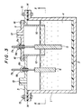
- FIG. 3 is a vertical cross-sectional view of an electrolytic cell for producing NF3 gas suitable for making the present invention.
- the cross-sectional view taken along line II - II of FIG. 3 is the same as FIG. 2.
- like reference numerals refer to like parts.
- a fluororesin plate is placed on the bottom plate of the electrolytic cell main body so as to inhibit corrosion of the bottom plate portion.
- fluororesin plate 2 is provided as shown in FIG. 3. Therefore, in this case, the bottom surface means the liquid contacting interface between the upper surface of the fluororesin plate and the electrolytic bath.
- the thickness of the fluororesin plate is not critical, but is usually 1 - 20 mm.
- a fluororesin for the purpose of preventing corrosion of the electrolytic cell, it is preferable to apply a fluororesin to parts contacting a molten salt and gases generated by electrolysis as well as the bottom plate part in the electrolytic cell (by lining or coating).
- bottom surface of the electrolytic cell is a liquid contacting interface between the upper surface of the fluororesin plate and the electrolytic bath when such a corrosion inhibiting material for the bottom plate is provided, but is a liquid contacting interface between the inner upper surface of the bottom plate of the electrolytic cell and the electrolytic bath when such a material as above is not present on the bottom plate.
- fluororesins those enumerated in the first aspect of the invention can be used.
- the bottom surface of the electrolytic cell in FIG.3 is the liquid contacting interface between the upper surface of fluororesin 2 and electrolytic bath 4.
- the lengths of an anode and a cathode are not critical. That is, one may be longer than the other and both may be the same length. In the following, the explanation will be made referring to a case where the anode is longer than the cathode, but the situation is also the same in a case where the cathode is longer than the anode.
- the distance between the lower end of anode 5 and the bottom surface of the electrolytic cell is 30 - 300 mm, preferably 50 - 200mm.
- the portion buried in the deposition can not function any more as electrode so that the area acting as electrode decreases, and thereby the electric current density increases and the voltage in the electrolytic cell rises, and further, the yield (electric current efficiency for producing NF3) is lowered.
- electrolytic cell gets larger accordingly resulting in an excess investment.
- the electrolytic bath is so hygroscopic that it inevitably absorbs moisture in air at the stage of preparing the starting materials. Therefore, upon producing NF3 dehydration electrolysis is essential which is effected by applying an electric current having a current density lower than that upon a main electrolysis, and after completion of dehydration electrolysis, the main electrolysis starts continuously. Therefore, as the size of the electrolytic cell increases, the time for the dehydration electrolysis becomes longer, and the efficiency decreases disadvantageously.
- the distance between the lower end of the electrode and the bottom surface of the electrolytic cell is particularly specified as mentioned above.
- the particular distance it can be avoided that the dissolved nickel form an electrode deposits on the bottom surface of the electrolytic cell and an electrode is buried in the deposit as the lapse of time and finally the electrode can not function as electrode.
- a method for producing a nitrogen trifluoride gas by a molten salt electrolysis using an electrolytic cell which comprises an electrolytic bath composed of a molten salt, an anode and a cathode soaked in the electrolytic bath, and a lid fitted to the electrolytic cell for preventing evaporation of the electrolytic bath, the distance between the lid and the liquid surface of the electrolytic bath being in the range of 100 to 500 mm.
- the present inventors carried out researches on clogging of inlets and outlets of gases caused by evaporation of NH4F ⁇ HF in an electrolytic cell for producing NF3 according to a method of a molten salt electrolysis, and have found that clogging can be prevented by setting a particular numerical range of distance between the lid of the electrolytic cell and the liquid surface of the electrolytic bath and NF3 gas can be produced safely for a long period of time.
- the present invention has been completed.
- molten salt electrolysis for producing NF3 gas there is usually used acidic ammonium fluoride, NH4F ⁇ HF systems derived from ammonium fluoride and hydrogen fluoride, or KF NH4F ⁇ HF systems produced by adding acidic potassium fluoride or potassium fluoride to the NH4F ⁇ HF system.
- FIG. 1 and FIG. 2 are also used for the explanation of the first aspect.
- lid 3 of the electrolytic cell includes lid 11 for fixing partition plates
- liquid surface of electrolytic bath 4 is 100 - 500 mm.
- Electrolytic bath 4 may be a molten salt of a NH4F-HF system or KF-NH4F-HF system and electrolysis is carried out at a temperature of electrolytic bath of 100 - 130 °C.
- NF3 gas is generated at anode 5 and exhausted through anode gas outlet 12 while H2 generated at cathode 6 is exhausted through cathode gas outlet 13.
- inlets for N2 gas may be provided when an inert gas such as N2 gas is introduced into the electrolytic cell so as to help the gases generated at both electrodes flow and in such a case following is also applicable.
- lid 3 of the electrolytic cell The distance between lid 3 of the electrolytic cell and the liquid surface of electrolytic bath 4 is as mentioned above.
- H2 gas can not be exhausted from the cathode chamber, but H2 gas is continuously generated so that the pressure in the cathode chamber rises and the liquid surface in the cathode chamber is pushed down while the liquid surface in the anode chamber is pushed up.
- H2 gas in the cathode chamber enters the anode chamber to form an explosive gas mixture which is liable to explode in the anode chamber.
- the electrolytic bath is so hygroscopic that it inevitably absorbs moisture in air at the stage of preparing the starting materials. Therefore, upon producing NF3, a dehydration electrolysis is essential which is effected by applying an electric current having a current density lower than that upon a main electrolysis, and after completion of dehydration electrolysis, the main electrolysis starts continuously.
- the present inventors have found that when an electrolytic cell is too large, the dehydration electrolysis takes a long time and the dehydration efficiency is disadvantageously very low.
- a fluororesin plate is placed on the bottom plate of the electrolytic cell main body so as to inhibit corrosion of the bottom, plate portion.
- fluororesin plate 2 is provided as shown in FIG. 1.
- a fluororesin is applied to parts contacting with a molten salt and gases generated by electrolysis as well as the bottom plate part (by lining or coating) in the electrolytic cell.
- the fluororesins as enumerated in the first aspect may be also used in the third aspect of the present invention.
- NF3 gas can be safely produced for a long period of time by a molten salt electrolysis by selecting a particular distance between the lid of the electrolytic cell and the liquid surface of the electrolytic bath. That is, clogging of inlets of a carrier gas into the electrolytic cell or outlets of gases generated in the both electrode chambers can be avoided by selecting the particular distance.
- the distance between the bottom surface of the cell and the lower end of each of the anode and the cathode was 150 mm, and the distance between the lid of the electrolytic cell and the liquid surface of the molten salt bath was 250 mm.
- volume % is simply referred to a "%" after 100 hours. Therefore, it was recognized that dehydration electrolysis ended at this point.
- the electrolysis was transferred to a main electrolysis without interruption and the electrolysis was effected for a period of time as long as 3 months at 250 A (average current density of 10 A/dm2 at anode) while the concentration of H2 in the gas generated at anode and thatof NF3 in the gas generated at cathode were analyzed by gas chromatography. Each concentration was always at 1 % or less and naturally no explosion occurred, and NF3 was safely produced over a long period of time.
- Example 1 Following the procedure of Example 1 except that the distance between partition plate 10 and each of anode 5 and cathode 6 was as shown in Table 1, a dehydration electrolysis and a main electrolysis were carried out under the conditions as shown in Table 1 (the molten salt being the same as that in Example 1).
- the time of completion of dehydration electrolysis was considered to be a time at which the concentration of oxygen in the gas generated at anode measured by gas chromatography decreased gradually and reached a constant value of about 2 %.
- the time is shown in Table 1.
- Example 2 In a manner similar to Example 1, a long time continuous electrolysis was effected for 3 months while the concentration of H2 in the gas generated at anode and that of NF3 in the gas generated at cathode were analyzed by gas chromatography. Each concentration was always 1 % or less and naturally no explosion occurred, and NF3 was safely produced over a long period of time.
- Example 2 Repeating the procedure of Example 1 except that the distance between partition plate 10 and anode 5 and that between partition plate 10 and cathode 6 were as shown in Table 2 (one of the distances is outside of the numerical range of the present invention), dehydration electrolysis and a main electrolysis were carried out.
- the molten salt was the same as that used in Example 1.
- the time of completion of dehydration electrolysis was considered a time at which the concentration of oxygen in the gas generated at anode measured by gas chromatography decreased gradually and reached a constant value of about 2 %. And this time is shown in Table 2.
- Example 1 Repeating the procedure of Example 1 except that the distance between partition plate 10 and anode 5 and that between partition plate 10 and cathode 6 were as shown in Table 3 (one of the distances is outside of the numerical range of the present invention), dehydration electrolysis and a main electrolysis were carried out.
- the molten salt was the same as that used in Example 1.
- the time of completion of dehydration electrolysis was considered a time at which the concentration of oxygen in a gas generated at anode measured by gas chromatography decreased and reached a constant value of about 2 %.
- the time is shown in Table 3. This shows that the time is much longer than that in Examples 1 - 4 and the efficiency is not good.
- Example 2 Example 3 Example 4 Distance between anode and partition plate (mm) 100 50 150 Distance between cathode and partition plate (mm) 100 150 50 Time of completion of dehydration electrolysis 1) (hr) 100 120 110 Concentration of H2 at anode 2) (%) ⁇ 1.0 ⁇ 1.0 ⁇ 1.0 Concentration of NF3 at cathode 2) (%) ⁇ 1.0 ⁇ 1.0 ⁇ 1.0 Note: 1) A time at which the concentration of oxygen in the gas generated at anode measured by gas chromatography decreases gradually and reaches a constant value of about 2 %. 2) The concentration of H2 in the gas generated at anode and that of NF3 in the gas generated at cathode determined by gas chromatography after 3 months of the main electrolysis.
- the distance between the partition plate and each of the anode and the cathode was 150 mm and the distance between the lid of the electrolytic cell and the liquid surface was 250 mm.
- the concentration of oxygen in the gas generated at anode was analyzed by gas chromatography. The concentration gradually decreased and, after 80 hours, became constant at about 2 %. It was considered that the dehydration electrolysis ended at this time.
- the voltage in the electrolytic cell was less than 8 V, the temperature distribution in the electrolytic cell was within the range of 120 to 125 °C and the electric current efficiency of producing NF3 gas was a normal value, that is , 65 %, naturally there was no danger of explosion and NF3 was produced safely in good yield over a long period of time.
- Example 5 Repeating the procedure of Example 5 except that the distance between the bottom surface of the electrolytic cell (fluororesin plate 2) and each of the lower end of anode 5 and that of cathode 6 was as shown in Table 4, dehydration electrolysis and a main electrolysis were effected under the conditions in Table 4 (The molten salt being the same as that used in Example 5.).
- the time at which the dehydration electrolysis was considered to be completed i.e. a time when the concentration of oxygen in the gas generated at anode measured by gas chromatography decreased gradually and reached a constant value of about 2 %, was as shown in Table 4.
- Example 5 In a manner similar to Example 5, a three-month long continuous electrolysis was effected while the voltage and temperature distribution in the electrolytic cell and the electric current efficiency of NF3 gas generation were monitored.
- the voltage of electrolytic cell was less than 8 V
- the temperature distribution in the electrolytic cell was kept within the range of 120 to 125 °C
- the electric current efficiency of producing NF3 gas was a normal value, i.e. 65 %.
- Naturally NF3 was safely produced for a long period of time without any danger of explosion.
- Example 5 Repeating the procedure of Example 5 except that the distance between the bottom surface of the electrolytic cell (fluororesin plate 2) and the lower end of anode 5 and that between the bottom surface and the lower end of cathode 6 was as shown in Table 5(one of the distances is outside of the numerical range of the present invention), dehydration electrolysis and the main electrolysis were effected (the molten salt being the same as that in Example 5.).
- the time at which the dehydration electrolysis was considered to be completed i.e. a time when the concentration of oxygen in the gas generated at anode measured by gas chromatography decreased gradually and reached a constant value of about 2 %, was as shown in Table 5.
- Example 5 Repeating the procedure of Example 5 except that the distance between the bottom surface of the electrolytic cell (fluororesin plate 2) and the lower end of anode 5 and that between the bottom surface and the lower end of cathode 6 was as shown in Table 6 (outside of the numerical range of the present invention), dehydration electrolysis and the main electrolysis were effected (the molten salt being the same as that used in Example 5.).
- the time at which the dehydration electrolysis was considered to be completed i.e. a time when the concentration of oxygen in the gas generated at anode measured by gas chromatography decreased gradually and reached a constant value of about 2 %, was as shown in Table 6. This indicates that it took a much longer time than the time in Examples 5 - 8 and therefore the dehydration efficiency was poor.
- Example 7 Example 8 Distance between lower end of anode and bottom surface of electrolytic cell (mm) 200 50 250 Distance between lower end of cathode and bottom surface of electrolytic cell (mm) 200 250 50 Time of completion of dehydration electrolysis 1) (hr) 100 120 120 Electrolytic cell voltage 2) (V) 7.7 7.5 7.8 Temperature distribution in electrolytic cell 2) (°C) 120-125 120-125 120-125 Electric current efficiency of NF3 production 2) (%) 65 65 65 65 Note: 1) A time at which the concentration of oxygen in the gas generated at anode measured by gas chromatography decreases gradually and reaches a constant value of about 2 %. 2) Values after 3 months of the main electrolysis.
- A average electric current density of 2 A/dm2 at anode
- the distance between the partition plate and each of the anode and the cathode was 150 mm, and the distance between the bottom surface of the electrolytic cell and each of the lower end of the anode and that of the cathode was 150 mm.
- the concentration of oxygen in the gas generated at anode was analyzed by gas chromatography.
- the concentration of oxygen gradually decreased and after 80 hours of dehydration electrolysis, became constant at about 2 %. It was considered that dehydration electrolysis ended at this time.
- Example 9 Repeating the procedure of Example 9 except that the distance between lid 3 of the electrolytic cell and the liquid surface of electrolytic bath 4 was 400 mm, dehydration electrolysis and a main electrolysis were effected (the molten salt was the same as that in Example 9).
- Example 9 The time when the concentration of oxygen in the gas generated at anode measured by gas chromatography gradually decreased and reached a constant value of about 2 %, at which dehydration electrolysis was considered to end, was 100 hours. This time was somewhat longer than that in Example 9.
- a three-month long continuous electrolysis was carried out while amounts of flowing gases generated at anode and cathode were monitored and it was observed based on change with time whether clogging occurred. No change was found at both electrodes, and naturally no explosion occurred and NF3 was safely produced over a long period of time.
- Example 9 Repeating the procedure of Example 9 except that the distance between lid 3 of the electrolytic cell and the liquid surface of electrolytic bath 4 was 50 mm (outside of the numerical range of the present invention), dehydration electrolysis and a main electrolysis were carried out.
- the molten salt was the same as that in Example 9).
Landscapes
- Chemical & Material Sciences (AREA)
- Engineering & Computer Science (AREA)
- Chemical Kinetics & Catalysis (AREA)
- Electrochemistry (AREA)
- Materials Engineering (AREA)
- Metallurgy (AREA)
- Organic Chemistry (AREA)
- Inorganic Chemistry (AREA)
- Electrolytic Production Of Non-Metals, Compounds, Apparatuses Therefor (AREA)
- Electrolytic Production Of Metals (AREA)
Claims (1)
- Procédé pour la production d'un gaz de trifluorure d'azote par une électrolyse de sel en fusion en utilisant une cellule électrolytique qui comprend un bain électrolytique composé d'un sel en fusion, d'une anode et d'une cathode immergées dans le bain électrolytique de telle sorte que l'anode et la cathode sont placées de façon sensiblement perpendiculaire à la surface de fond de la cellule électrolytique, un couvercle étant adapté sur la cellule électrolytique pour empêcher l'évaporation du bain électrolytique, et une plaque de cloisonnement séparant l'anode et la cathode, la distance entre l'anode et la plaque de cloisonnement et la distance entre la cathode et la plaque de cloisonnement étant dans la plage de 30 à 200 mm, la distance entre l'extrémité inférieure de l'anode et la surface de fond de la cellule électrolytique et la distance entre l'extrémité inférieure de la cathode et de la surface de fond de la cellule électrolytique étant dans la plage de 30 à 300 mm, et la distance entre le couvercle et la surface liquide du bain électrolytique se situant dans la plage de 100 à 500 mm.
Applications Claiming Priority (6)
| Application Number | Priority Date | Filing Date | Title |
|---|---|---|---|
| JP277248/89 | 1989-10-26 | ||
| JP1277248A JPH03140488A (ja) | 1989-10-26 | 1989-10-26 | 電解槽 |
| JP309092/89 | 1989-11-30 | ||
| JP309093/89 | 1989-11-30 | ||
| JP1309093A JP2698457B2 (ja) | 1989-11-30 | 1989-11-30 | 電解槽 |
| JP1309092A JP2764623B2 (ja) | 1989-11-30 | 1989-11-30 | 電解槽 |
Publications (2)
| Publication Number | Publication Date |
|---|---|
| EP0424727A1 EP0424727A1 (fr) | 1991-05-02 |
| EP0424727B1 true EP0424727B1 (fr) | 1995-04-19 |
Family
ID=27336438
Family Applications (1)
| Application Number | Title | Priority Date | Filing Date |
|---|---|---|---|
| EP90119385A Expired - Lifetime EP0424727B1 (fr) | 1989-10-26 | 1990-10-10 | Procédé de production de trifluorure d'azote |
Country Status (4)
| Country | Link |
|---|---|
| US (2) | US5085752A (fr) |
| EP (1) | EP0424727B1 (fr) |
| KR (1) | KR930001975B1 (fr) |
| DE (1) | DE69018761T2 (fr) |
Families Citing this family (21)
| Publication number | Priority date | Publication date | Assignee | Title |
|---|---|---|---|---|
| JPH01261208A (ja) * | 1988-04-11 | 1989-10-18 | Mitsui Toatsu Chem Inc | 三弗化窒素ガスの精製方法 |
| GB9418598D0 (en) * | 1994-09-14 | 1994-11-02 | British Nuclear Fuels Plc | Fluorine cell |
| US5628894A (en) * | 1995-10-17 | 1997-05-13 | Florida Scientific Laboratories, Inc. | Nitrogen trifluoride process |
| US6210549B1 (en) | 1998-11-13 | 2001-04-03 | Larry A. Tharp | Fluorine gas generation system |
| SG80671A1 (en) * | 1999-02-10 | 2001-05-22 | Mitsui Chemicals Inc | A process for producing high-purity nitrogen trifluoride gas |
| SG87196A1 (en) * | 1999-12-21 | 2002-03-19 | Mitsui Chemicals Inc | Electrode and electrolyte for use in preparation of nitrogen trifluoride gas, and preparation method of nitrogen trifluoride gas by use of them |
| US6818105B2 (en) * | 2000-04-07 | 2004-11-16 | Toyo Tanso Co., Ltd. | Apparatus for generating fluorine gas |
| US6986874B2 (en) | 2000-12-14 | 2006-01-17 | The Boc Group, Inc. | Method and apparatus for the production of nitrogen trifluoride |
| FR2824336B1 (fr) * | 2001-05-07 | 2004-11-12 | Conversion De L Uranium En Met | Procede de preparation de trifluorure d'azote nf3 par electrolyse et installation pour sa mise en oeuvre |
| KR100541978B1 (ko) * | 2001-08-17 | 2006-01-16 | 주식회사 효성 | 고순도 삼불화질소 제조용 전해조 및 삼불화질소의 제조방법 |
| US6908601B2 (en) * | 2002-02-08 | 2005-06-21 | The Boc Group, Inc. | Method for the production of nitrogen trifluoride |
| RU2274601C1 (ru) * | 2005-03-31 | 2006-04-20 | Зао Астор Электроникс | Способ получения трифторида азота |
| FR2921389B1 (fr) * | 2007-09-25 | 2010-03-12 | Commissariat Energie Atomique | Electrolyseur haute temperature a dispositif de recuperation d'hydrogene. |
| US8945367B2 (en) | 2011-01-18 | 2015-02-03 | Air Products And Chemicals, Inc. | Electrolytic apparatus, system and method for the safe production of nitrogen trifluoride |
| WO2013001800A1 (fr) * | 2011-06-29 | 2013-01-03 | 東洋炭素株式会社 | Dispositif d'électrolyse |
| KR101223376B1 (ko) * | 2011-12-19 | 2013-01-23 | 오씨아이머티리얼즈 주식회사 | 삼불화질소 가스 제조용 전해조 |
| US9528191B2 (en) | 2014-02-26 | 2016-12-27 | Air Products And Chemicals, Inc. | Electrolytic apparatus, system and method for the efficient production of nitrogen trifluoride |
| WO2017057950A1 (fr) | 2015-10-02 | 2017-04-06 | 후성정공 주식회사 | Collecteur d'électrolyseur pour fabriquer du trifluorure d'azote et son procédé de fabrication |
| KR102258314B1 (ko) * | 2017-06-30 | 2021-06-01 | 쇼와 덴코 가부시키가이샤 | 불소 전해조 양극 설치부, 불소 전해조 및 불소 가스의 제조 방법 |
| US10955375B2 (en) * | 2018-03-16 | 2021-03-23 | U.S. Department Of Energy | Multielectrode sensor for concentration and depth measurements in molten salt |
| CN108265313A (zh) * | 2018-03-27 | 2018-07-10 | 浙江长控电气科技有限公司 | 电解装置及用其电解稀食盐水制取酸性和碱性溶液的方法 |
Family Cites Families (10)
| Publication number | Priority date | Publication date | Assignee | Title |
|---|---|---|---|---|
| US1311231A (en) * | 1919-07-29 | Process of making nitrogen compounds | ||
| US1113599A (en) * | 1911-08-08 | 1914-10-13 | Nitrogen Products Company | Method of fixing nitrogen. |
| US1597231A (en) * | 1922-03-23 | 1926-08-24 | Pierre E Haynes | Electrolytic production of alkali metals |
| FR968142A (fr) * | 1947-06-28 | 1950-11-20 | Pennsylvania Salt Mfg Co | Perfectionnements apportés aux procédés et appareils pour l'obtention de fluor par électrolyse |
| US2958634A (en) * | 1959-05-27 | 1960-11-01 | Du Pont | Preparation of fluorinated hydrazines |
| US3235474A (en) * | 1961-10-02 | 1966-02-15 | Air Prod & Chem | Electrolytic method of producing nitrogen trifluoride |
| JPS6071503A (ja) * | 1983-09-27 | 1985-04-23 | Central Glass Co Ltd | Νf↓3の製造法 |
| DE3722163A1 (de) * | 1987-07-04 | 1989-01-12 | Kali Chemie Ag | Verfahren zur herstellung von nf(pfeil abwaerts)3(pfeil abwaerts) |
| JPH0755807B2 (ja) * | 1987-11-04 | 1995-06-14 | 三井東圧化学株式会社 | 三弗化窒素の製造方法 |
| EP0366078B1 (fr) * | 1988-10-25 | 1996-06-26 | MITSUI TOATSU CHEMICALS, Inc. | Méthode pour la purification de trifluorure d'azote gazeux |
-
1990
- 1990-10-10 US US07/595,284 patent/US5085752A/en not_active Expired - Lifetime
- 1990-10-10 EP EP90119385A patent/EP0424727B1/fr not_active Expired - Lifetime
- 1990-10-10 DE DE69018761T patent/DE69018761T2/de not_active Expired - Lifetime
- 1990-10-26 KR KR1019900017250A patent/KR930001975B1/ko not_active Expired - Lifetime
-
1991
- 1991-02-26 US US07/660,743 patent/US5084156A/en not_active Expired - Lifetime
Also Published As
| Publication number | Publication date |
|---|---|
| KR930001975B1 (ko) | 1993-03-20 |
| DE69018761T2 (de) | 1995-12-07 |
| US5084156A (en) | 1992-01-28 |
| DE69018761D1 (de) | 1995-05-24 |
| EP0424727A1 (fr) | 1991-05-02 |
| KR910008172A (ko) | 1991-05-30 |
| US5085752A (en) | 1992-02-04 |
Similar Documents
| Publication | Publication Date | Title |
|---|---|---|
| EP0424727B1 (fr) | Procédé de production de trifluorure d'azote | |
| JP3343139B2 (ja) | フッ素ガスの電解製造用電極及び電解槽並びにフッ素ガスの電解製造法並びに直接フッ素化法 | |
| US20100116649A1 (en) | Gas generating device and carbon electrode for gas generation | |
| SE441010B (sv) | Forfarande for genomforande av elektrolys | |
| US5160415A (en) | Carbon electrode, and method and apparatus for the electrolysis of a hydrogen fluoride-containing molten salt with the carbon electrode | |
| CA1195949A (fr) | Electrolyse du chlorure d'hydrogene dans une pile a membrane en polymere avec electrodes a meme | |
| JP3485928B2 (ja) | フッ素電解槽 | |
| US5474659A (en) | Process and apparatus for generating precursor gases used in the manufacture of semiconductor devices | |
| US3772201A (en) | Electrode for electrolytic conversion cells including passage means in the electrode for electrolyte flow through the electrode | |
| KR100541978B1 (ko) | 고순도 삼불화질소 제조용 전해조 및 삼불화질소의 제조방법 | |
| US3109788A (en) | Electrolytic production of phosphine | |
| US3361656A (en) | Wicking electrode for an electrolytic cell | |
| KR100447420B1 (ko) | 3불화질소가스의 제조에 사용되는 전극 | |
| JP2698457B2 (ja) | 電解槽 | |
| JP2764623B2 (ja) | 電解槽 | |
| KR20230174648A (ko) | 고순도 pftpa의 제조 장치 및 방법 | |
| JP2766845B2 (ja) | 電解槽 | |
| KR100288862B1 (ko) | 개선된불소의제조방법 | |
| EP0663459A1 (fr) | Appareil produisant de l'hydrogene et de l'oxygene | |
| JPH0757915B2 (ja) | 改良された電解槽 | |
| KR20070057489A (ko) | 기화되는 불산을 최소화한 고순도 삼불화질소 제조용전해조 및 이를 이용한 삼불화 질소의 제조방법 | |
| JP3986175B2 (ja) | 三弗化窒素ガスの製造方法 | |
| JPS6147230B2 (fr) | ||
| KR20180126658A (ko) | 열변형이 개선된 삼불화질소 제조용 전해조의 가스 포집체 | |
| JP2000064075A (ja) | 電解槽 |
Legal Events
| Date | Code | Title | Description |
|---|---|---|---|
| PUAI | Public reference made under article 153(3) epc to a published international application that has entered the european phase |
Free format text: ORIGINAL CODE: 0009012 |
|
| 17P | Request for examination filed |
Effective date: 19901221 |
|
| AK | Designated contracting states |
Kind code of ref document: A1 Designated state(s): BE DE FR GB |
|
| 17Q | First examination report despatched |
Effective date: 19930402 |
|
| GRAA | (expected) grant |
Free format text: ORIGINAL CODE: 0009210 |
|
| AK | Designated contracting states |
Kind code of ref document: B1 Designated state(s): BE DE FR GB |
|
| PG25 | Lapsed in a contracting state [announced via postgrant information from national office to epo] |
Ref country code: BE Effective date: 19950419 |
|
| REF | Corresponds to: |
Ref document number: 69018761 Country of ref document: DE Date of ref document: 19950524 |
|
| ET | Fr: translation filed | ||
| PLBE | No opposition filed within time limit |
Free format text: ORIGINAL CODE: 0009261 |
|
| STAA | Information on the status of an ep patent application or granted ep patent |
Free format text: STATUS: NO OPPOSITION FILED WITHIN TIME LIMIT |
|
| 26N | No opposition filed | ||
| REG | Reference to a national code |
Ref country code: GB Ref legal event code: 732E |
|
| REG | Reference to a national code |
Ref country code: FR Ref legal event code: TP |
|
| REG | Reference to a national code |
Ref country code: GB Ref legal event code: IF02 |
|
| PGFP | Annual fee paid to national office [announced via postgrant information from national office to epo] |
Ref country code: GB Payment date: 20021009 Year of fee payment: 13 |
|
| PG25 | Lapsed in a contracting state [announced via postgrant information from national office to epo] |
Ref country code: GB Free format text: LAPSE BECAUSE OF NON-PAYMENT OF DUE FEES Effective date: 20031010 |
|
| GBPC | Gb: european patent ceased through non-payment of renewal fee |
Effective date: 20031010 |
|
| PGFP | Annual fee paid to national office [announced via postgrant information from national office to epo] |
Ref country code: DE Payment date: 20091008 Year of fee payment: 20 |
|
| PGFP | Annual fee paid to national office [announced via postgrant information from national office to epo] |
Ref country code: FR Payment date: 20091029 Year of fee payment: 20 |
|
| PG25 | Lapsed in a contracting state [announced via postgrant information from national office to epo] |
Ref country code: DE Free format text: LAPSE BECAUSE OF EXPIRATION OF PROTECTION Effective date: 20101010 |