EP0424730A2 - Dispositif pour robot industriel - Google Patents
Dispositif pour robot industriel Download PDFInfo
- Publication number
- EP0424730A2 EP0424730A2 EP90119405A EP90119405A EP0424730A2 EP 0424730 A2 EP0424730 A2 EP 0424730A2 EP 90119405 A EP90119405 A EP 90119405A EP 90119405 A EP90119405 A EP 90119405A EP 0424730 A2 EP0424730 A2 EP 0424730A2
- Authority
- EP
- European Patent Office
- Prior art keywords
- industrial robot
- workpieces
- removal
- unit
- pallet
- Prior art date
- Legal status (The legal status is an assumption and is not a legal conclusion. Google has not performed a legal analysis and makes no representation as to the accuracy of the status listed.)
- Granted
Links
Images


Classifications
-
- G—PHYSICS
- G05—CONTROLLING; REGULATING
- G05B—CONTROL OR REGULATING SYSTEMS IN GENERAL; FUNCTIONAL ELEMENTS OF SUCH SYSTEMS; MONITORING OR TESTING ARRANGEMENTS FOR SUCH SYSTEMS OR ELEMENTS
- G05B19/00—Program-control systems
- G05B19/02—Program-control systems electric
- G05B19/18—Numerical control [NC], i.e. automatically operating machines, in particular machine tools, e.g. in a manufacturing environment, so as to execute positioning, movement or co-ordinated operations by means of program data in numerical form
- G05B19/406—Numerical control [NC], i.e. automatically operating machines, in particular machine tools, e.g. in a manufacturing environment, so as to execute positioning, movement or co-ordinated operations by means of program data in numerical form characterised by monitoring or safety
- G05B19/4063—Monitoring general control system
-
- Y—GENERAL TAGGING OF NEW TECHNOLOGICAL DEVELOPMENTS; GENERAL TAGGING OF CROSS-SECTIONAL TECHNOLOGIES SPANNING OVER SEVERAL SECTIONS OF THE IPC; TECHNICAL SUBJECTS COVERED BY FORMER USPC CROSS-REFERENCE ART COLLECTIONS [XRACs] AND DIGESTS
- Y02—TECHNOLOGIES OR APPLICATIONS FOR MITIGATION OR ADAPTATION AGAINST CLIMATE CHANGE
- Y02P—CLIMATE CHANGE MITIGATION TECHNOLOGIES IN THE PRODUCTION OR PROCESSING OF GOODS
- Y02P90/00—Enabling technologies with a potential contribution to greenhouse gas [GHG] emissions mitigation
- Y02P90/02—Total factory control, e.g. smart factories, flexible manufacturing systems [FMS] or integrated manufacturing systems [IMS]
Definitions
- the present invention relates to countermeasures against an abnormal stop of an industrial robot apparatus for loading workpieces on a pallet.
- An industrial robot apparatus with a fail safe means against an abnormal state such as an earthquake has been known as disclosed in Japanese Patent Laid Open Publication No. SHO 61-88301 and so forth.
- This industrial robot apparatus is structured so that an industrial robot is stopped when an abnormality occurs.
- An object of the present invention is to solve such a problem and to provide an industrial robot apparatus where no loading failure takes place when it is restarted after an abnormal stop.
- An industrial robot apparatus comprises a control unit for controlling an industrial robot and peripheral unit thereof by using a program so as to load workpieces on a pallet, abnormal stop means for detecting an abnormality which occurs in at least either of the industrial robot and the peripheral unit and for stopping both of the industrial robot and the peripheral unit, storage means for storing a step of the program which is being executed when the abnormal stop takes place, and removal means for removing remaining workpieces to be loaded on a pallet in steps following the stored step of the storage means.
- the industrial robot apparatus since the industrial robot apparatus stores the program step in which the abnormal stop means operates and removes remaining workpieces which are being loaded to a pallet in the step following the stored step by the removal means.
- the industrial robot apparatus is restored from the abnormality and it is restarted, it is possible to prevent the workpieces from being improperly loaded to the pallet and thereby improving the reliability of the operations.
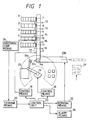
- Figs. 1 to 4 are schematics showing an embodiment of the present invention.
- Reference numerals 1 to 5 designate receiving units, each of which is a conveyer for carrying particular workpieces different from others, respectively.
- the reference numeral 1 is a first receiving unit; 2 is a second receiving unit; 3 is a third receiving unit; 4 is a fourth receiving unit; and 5 is a fifth receiving unit, respectively.
- Reference numeral 6 is a supply conveyer disposed perpendicular to each end of the first receiving unit 1 to the fifth receiving unit 5, the supply conveyer 6 having a stopper 6a at one end.
- Reference numerals 7 to 11 are blocking mechanisms disposed at one end of each of the first receiving unit 1 to the fifth receiving unit 5, respectively.
- Reference numerals 12 to 16 are counting units which are provided corresponding to the first receiving unit 1 to the fifth receiving unit 5, respectively, the optical path of each counting unit being traversed by the supply conveyer 6.
- Reference numeral 17 is a peripheral unit which is a supply unit comprising the supply conveyer 6, the blocking mechanisms 7 to 11, the counting units 12 to 16, and a control means 18.
- Reference numeral 19 is an industrial robot disposed at the end of the supply conveyer 6, the industrial robot 19 having a hand 19a.
- Reference numeral 20 is a control means for the industrial robot 19.
- Reference numeral 21 is a pallet disposed at a particular position close to the industrial robot 19.
- Reference numeral 21, is a pallet on which workpieces are being loaded, the pallet being removed.
- Reference numeral 22 is a removal means including a removal program executed when an abnormal stop takes place, the removal means being provided with a removal extruding unit 22a and a removal conveyer 22b, which are disposed at the end of the supply conveyer 6.
- Reference numeral 23 is a control unit including a program for supplying workpieces and for loading them on a pallet, the control unit 23 being a computer comprising an I/O port 23a, a RAM 23b, a CPU 23c, and a ROM 23d.
- Reference numeral 24 is an abnormal stop means for detecting abnormalities of the peripheral unit 17 and the industrial robot 19 and for executing abnormal stops for them.
- Reference numeral 24a is a vision sensor of the abnormal stop means 24, the vision sensor 24a downwardly monitoring the pallet 21 on which workpieces are being loaded.
- Reference numeral 25 is a storage means for storing a program step in which an abnormal stop takes place.
- Reference numeral 26 is an alarm means for informing the operator of the occurrence of the abnormal stop.
- the peripheral unit 17 and the industrial robot 19 are operated through the control unit 23 according to a load command.
- Workpieces whose type and quantity are commanded are supplied by the peripheral unit 17 and loaded on the pallet 21 by the industrial robot 19 in the programmed conditions.
- the pallet 21 where the workpieces have been loaded is sent to a shipment place or the like.
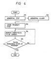
- the abnormal stop means 24 When an abnormality takes place, the abnormal stop means 24 operates and thereby the peripheral unit 17 and the industrial robot 19 are abnormally stopped in the step 101. After that, the alarm means 26 is activated and an abnormal alarm is issued in the step 102. Subsequently, the storage means 25 stores the program step in which the abnormal stop takes place in the step 103. Then, the removal means 22 operates in the step 104. In the step 104, the remaining workpieces to be loaded in the steps following the stored step are removed by the operations of the peripheral unit 17, the removal extruding unit 22a and the removal conveyer 22b according to a command from the removal program.
- the remaining workpiece removal operation in the step 104 is repeated until the remaining steps of the program which are executed after the abnormal stop takes place are completed.
- the removed workpieces and the pallet for which the loading operation has not yet been completed are transferred after the former have been manually loaded on the latter.
- the removed workpieces are sent to the corresponding receiving units 1 to 5, respectively.
- Fig. 5 is a schematic showing another embodiment of the present invention.
- the same reference numerals as Figs. 1 to 4 represent same portions, respectively.
- Reference numerals 22c to 22g are units structuring part of the removal means 22.
- the reference numeral 22c is a first section conveyer whose end is in contact with the removal conveyer 22b and which accords with the first receiving unit 1.
- the numeral 22d is a second section conveyer which is disposed like the first section conveyer 22c and which accords with the second receiving unit 2.
- the numeral 22e is a third section conveyer which is disposed like the first section conveyer 22c and which accords with the third receiving unit 3.
- the numeral 22f is a fourth section conveyer which is disposed like the first section conveyer 22c and which accords with the fourth receiving unit 4.
- the numeral 22g is a fifth section conveyer which is disposed like the first section conveyer 22c and which accords with the fifth receiving unit 5.
- the numeral 22h is a first stopper which is disposed on the removal conveyer 22b and which accords with the first section conveyer 22c.
- the numeral 22i is a second stopper which is disposed on the removal conveyer 22b and which accords with the second section conveyer 22d.
- the numeral 22j is a third stopper which is disposed on the removal conveyer 22b and which accords with the third section conveyer 22e.
- the numeral 22k is a fourth stopper which is disposed on the removal conveyer 22b and which accords with the fourth section conveyer 22f.
- the numeral 221 is a fifth stopper which is disposed on the removal conveyer 22b and which accords with the fifth section conveyer 22g.
- the numeral 22m is a first extruding unit which is disposed on the removal conveyer 22b and which accords with the first section conveyer 22c.
- the numeral 22n is a second extruding unit which is disposed on the removal conveyer 22b and which accords with the second section conveyer 22d.
- the numeral 220 is a third extruding unit which is disposed on the removal conveyer 22b and which accords with the third section conveyer 22e.
- the numeral 22p is a fourth extruding unit which is disposed on the removal conveyer 22b and which accords with the fourth section conveyer 22f.
- the numeral 22q is a fifth extruding unit which is disposed on the removal conveyer 22b and which accords with the fifth section conveyer 22g.
- the workpieces which are removed when the abnormal stop takes place are sent to the first section conveyer 22c to the fifth section conveyer 22g.
- the workpieces which are sent to the first section conveyer 22m to the fifth section conveyer 22q are returned to the first receiving unit 1 to the fifth receiving unit 5. Consequently, the labor required when an abnormal stop takes place can be saved.
Landscapes
- Engineering & Computer Science (AREA)
- Human Computer Interaction (AREA)
- Manufacturing & Machinery (AREA)
- Physics & Mathematics (AREA)
- General Physics & Mathematics (AREA)
- Automation & Control Theory (AREA)
- Manipulator (AREA)
- Control Of Conveyors (AREA)
- Safety Devices In Control Systems (AREA)
- Feeding Of Workpieces (AREA)
Applications Claiming Priority (2)
| Application Number | Priority Date | Filing Date | Title |
|---|---|---|---|
| JP276412/89 | 1989-10-24 | ||
| JP1276412A JPH03136739A (ja) | 1989-10-24 | 1989-10-24 | 産業用ロボット装置 |
Publications (3)
| Publication Number | Publication Date |
|---|---|
| EP0424730A2 true EP0424730A2 (fr) | 1991-05-02 |
| EP0424730A3 EP0424730A3 (en) | 1993-04-21 |
| EP0424730B1 EP0424730B1 (fr) | 1996-07-24 |
Family
ID=17569047
Family Applications (1)
| Application Number | Title | Priority Date | Filing Date |
|---|---|---|---|
| EP90119405A Expired - Lifetime EP0424730B1 (fr) | 1989-10-24 | 1990-10-10 | Dispositif pour robot industriel |
Country Status (3)
| Country | Link |
|---|---|
| EP (1) | EP0424730B1 (fr) |
| JP (1) | JPH03136739A (fr) |
| DE (1) | DE69027904T2 (fr) |
Cited By (2)
| Publication number | Priority date | Publication date | Assignee | Title |
|---|---|---|---|---|
| EP1225002A1 (fr) * | 2001-01-12 | 2002-07-24 | Grundfos A/S | Dispositif robotisé comportant deux robots disposés coaxialement et entourés par plusieurs stations de travail |
| EP3693298A1 (fr) * | 2019-02-06 | 2020-08-12 | ISHIDA CO., Ltd. | Appareil d'accumulation d'articles |
Family Cites Families (6)
| Publication number | Priority date | Publication date | Assignee | Title |
|---|---|---|---|---|
| DE2513655C3 (de) * | 1975-03-27 | 1979-11-29 | Fraunhofer-Gesellschaft Zur Foerderung Der Angewandten Forschung E.V., 8000 Muenchen | Einrichtung für die Steuerung von automatischen Handhabungssystemen mittels Fernsehkamera |
| US4418398A (en) * | 1979-09-04 | 1983-11-29 | General Electric Company | Manual reset control circuit for microprocessor controlled washing appliance |
| DE3229327A1 (de) * | 1982-08-06 | 1984-02-16 | Mannesmann AG, 4000 Düsseldorf | Versorgungssystem |
| US4638227A (en) * | 1984-01-18 | 1987-01-20 | Hitachi, Ltd. | Method and apparatus for recovering normality in moving sequence of machinery |
| JPS6188301A (ja) * | 1984-10-05 | 1986-05-06 | Mitsubishi Electric Corp | 産業用ロボツト装置 |
| DE3630904A1 (de) * | 1985-09-14 | 1987-04-30 | Barmag Barmer Maschf | Verfahren und vorrichtung zum beladen von textilmaschinen mit vorlagespulen |
-
1989
- 1989-10-24 JP JP1276412A patent/JPH03136739A/ja active Pending
-
1990
- 1990-10-10 EP EP90119405A patent/EP0424730B1/fr not_active Expired - Lifetime
- 1990-10-10 DE DE69027904T patent/DE69027904T2/de not_active Expired - Fee Related
Cited By (3)
| Publication number | Priority date | Publication date | Assignee | Title |
|---|---|---|---|---|
| EP1225002A1 (fr) * | 2001-01-12 | 2002-07-24 | Grundfos A/S | Dispositif robotisé comportant deux robots disposés coaxialement et entourés par plusieurs stations de travail |
| EP3693298A1 (fr) * | 2019-02-06 | 2020-08-12 | ISHIDA CO., Ltd. | Appareil d'accumulation d'articles |
| US11111083B2 (en) | 2019-02-06 | 2021-09-07 | Ishida Co., Ltd. | Article accumulating apparatus |
Also Published As
| Publication number | Publication date |
|---|---|
| EP0424730A3 (en) | 1993-04-21 |
| JPH03136739A (ja) | 1991-06-11 |
| EP0424730B1 (fr) | 1996-07-24 |
| DE69027904T2 (de) | 1997-01-16 |
| DE69027904D1 (de) | 1996-08-29 |
Similar Documents
| Publication | Publication Date | Title |
|---|---|---|
| US5293322A (en) | Industrial robot apparatus | |
| EP0192157B2 (fr) | Machine-outil à commande numérique avec fonction d'arrêt en cas d'erreurs | |
| JPS6244281B2 (fr) | ||
| JPH01192485A (ja) | 自動溶接機における溶接ガンの電極チップ管理方法 | |
| US5742624A (en) | Fault detecting apparatus and method | |
| EP0471860B1 (fr) | Procede de commande de robot apres une interruption de service | |
| EP0373222B1 (fr) | Organe de commande d'arret d'outil de coupe | |
| EP0424730B1 (fr) | Dispositif pour robot industriel | |
| EP0100684A2 (fr) | Dispositif et méthode de commande d'un poste de fabrication | |
| EP0418714B1 (fr) | Système pour robot industriel | |
| JP3091572B2 (ja) | 電源異常対応制御を備えた数値制御工作機械装置 | |
| US4947349A (en) | Monitoring systems in sequential program control arrangements | |
| JP3246360B2 (ja) | 自動加工装置および自動加工方法 | |
| JPS6288540A (ja) | Fmsにおける加工工具処理装置 | |
| EP0915403A1 (fr) | Calculateur numerique | |
| KR19990068946A (ko) | 반도체 습식 설비의 구조 및 이의 로트 로딩/언로딩 방법 | |
| JP2664428B2 (ja) | ワーク搬入出装置におけるアラーム来歴管理装置 | |
| JP3745906B2 (ja) | 生産システム | |
| JPH10328972A (ja) | 数値制御加工方法および装置 | |
| US20250199502A1 (en) | Data collecting device and computer-readable storage medium | |
| JP2002169607A (ja) | Fmsセルにおける加工異常パレットの管理方法および装置 | |
| JPH0444281B2 (fr) | ||
| JP2590108B2 (ja) | シーケンスプログラム制御系のモニタ装置 | |
| JPH11231916A (ja) | 工作機械の数値制御装置 | |
| CN118821011A (zh) | 一种高压设备故障首出判断方法 |
Legal Events
| Date | Code | Title | Description |
|---|---|---|---|
| PUAI | Public reference made under article 153(3) epc to a published international application that has entered the european phase |
Free format text: ORIGINAL CODE: 0009012 |
|
| 17P | Request for examination filed |
Effective date: 19901220 |
|
| AK | Designated contracting states |
Kind code of ref document: A2 Designated state(s): DE GB SE |
|
| PUAL | Search report despatched |
Free format text: ORIGINAL CODE: 0009013 |
|
| AK | Designated contracting states |
Kind code of ref document: A3 Designated state(s): DE GB SE |
|
| 17Q | First examination report despatched |
Effective date: 19950412 |
|
| GRAH | Despatch of communication of intention to grant a patent |
Free format text: ORIGINAL CODE: EPIDOS IGRA |
|
| GRAA | (expected) grant |
Free format text: ORIGINAL CODE: 0009210 |
|
| AK | Designated contracting states |
Kind code of ref document: B1 Designated state(s): DE GB SE |
|
| GRAH | Despatch of communication of intention to grant a patent |
Free format text: ORIGINAL CODE: EPIDOS IGRA |
|
| REF | Corresponds to: |
Ref document number: 69027904 Country of ref document: DE Date of ref document: 19960829 |
|
| PLBE | No opposition filed within time limit |
Free format text: ORIGINAL CODE: 0009261 |
|
| STAA | Information on the status of an ep patent application or granted ep patent |
Free format text: STATUS: NO OPPOSITION FILED WITHIN TIME LIMIT |
|
| 26N | No opposition filed | ||
| PGFP | Annual fee paid to national office [announced via postgrant information from national office to epo] |
Ref country code: SE Payment date: 19981006 Year of fee payment: 9 |
|
| PGFP | Annual fee paid to national office [announced via postgrant information from national office to epo] |
Ref country code: GB Payment date: 19981016 Year of fee payment: 9 Ref country code: DE Payment date: 19981016 Year of fee payment: 9 |
|
| PG25 | Lapsed in a contracting state [announced via postgrant information from national office to epo] |
Ref country code: GB Free format text: LAPSE BECAUSE OF NON-PAYMENT OF DUE FEES Effective date: 19991010 |
|
| PG25 | Lapsed in a contracting state [announced via postgrant information from national office to epo] |
Ref country code: SE Free format text: THE PATENT HAS BEEN ANNULLED BY A DECISION OF A NATIONAL AUTHORITY Effective date: 19991030 |
|
| GBPC | Gb: european patent ceased through non-payment of renewal fee |
Effective date: 19991010 |
|
| EUG | Se: european patent has lapsed |
Ref document number: 90119405.0 |
|
| PG25 | Lapsed in a contracting state [announced via postgrant information from national office to epo] |
Ref country code: DE Free format text: LAPSE BECAUSE OF NON-PAYMENT OF DUE FEES Effective date: 20000801 |