EP0424733A1 - Dispositif pour charger des boulons d'ancrage - Google Patents
Dispositif pour charger des boulons d'ancrage Download PDFInfo
- Publication number
- EP0424733A1 EP0424733A1 EP90119457A EP90119457A EP0424733A1 EP 0424733 A1 EP0424733 A1 EP 0424733A1 EP 90119457 A EP90119457 A EP 90119457A EP 90119457 A EP90119457 A EP 90119457A EP 0424733 A1 EP0424733 A1 EP 0424733A1
- Authority
- EP
- European Patent Office
- Prior art keywords
- drilling
- excavation equipment
- shaped
- movable arm
- movable
- Prior art date
- Legal status (The legal status is an assumption and is not a legal conclusion. Google has not performed a legal analysis and makes no representation as to the accuracy of the status listed.)
- Withdrawn
Links
- 230000002787 reinforcement Effects 0.000 title claims abstract description 44
- 238000005553 drilling Methods 0.000 claims abstract description 54
- 238000009412 basement excavation Methods 0.000 claims abstract description 44
- 230000014759 maintenance of location Effects 0.000 claims 1
- 239000004568 cement Substances 0.000 description 6
- 238000003780 insertion Methods 0.000 description 4
- 230000037431 insertion Effects 0.000 description 4
- 230000000712 assembly Effects 0.000 description 2
- 238000000429 assembly Methods 0.000 description 2
- 239000000463 material Substances 0.000 description 2
- 238000005266 casting Methods 0.000 description 1
- 230000001419 dependent effect Effects 0.000 description 1
- 238000010586 diagram Methods 0.000 description 1
- 238000000034 method Methods 0.000 description 1
- 239000003381 stabilizer Substances 0.000 description 1
Images


Classifications
-
- E—FIXED CONSTRUCTIONS
- E21—EARTH OR ROCK DRILLING; MINING
- E21D—SHAFTS; TUNNELS; GALLERIES; LARGE UNDERGROUND CHAMBERS
- E21D5/00—Lining shafts; Linings therefor
-
- E—FIXED CONSTRUCTIONS
- E21—EARTH OR ROCK DRILLING; MINING
- E21D—SHAFTS; TUNNELS; GALLERIES; LARGE UNDERGROUND CHAMBERS
- E21D20/00—Setting anchoring-bolts
- E21D20/003—Machines for drilling anchor holes and setting anchor bolts
-
- E—FIXED CONSTRUCTIONS
- E21—EARTH OR ROCK DRILLING; MINING
- E21B—EARTH OR ROCK DRILLING; OBTAINING OIL, GAS, WATER, SOLUBLE OR MELTABLE MATERIALS OR A SLURRY OF MINERALS FROM WELLS
- E21B19/00—Handling rods, casings, tubes or the like outside the borehole, e.g. in the derrick; Apparatus for feeding the rods or cables
- E21B19/20—Combined feeding from rack and connecting, e.g. automatically
Definitions
- This invention concerns a device to load reinforcement rods.
- the invention concerns a device suitable to cooperate with an excavation equipment in moving the drilling shaft before and after the drilling of a hole and in feeding on the excavation equipment the non-recoverable reinforcement rods employed in lengthwise reinforcements in tunnels.
- the device of the invention and the excavation equipment are normally carried on an excavation machine operating at the working face.
- the state of the art includes various methods and devices employed in the reinforcement of tunnels.
- One of the systems most often used consists in carrying out a series of lengthwise drillings about the vault of the tunnel.
- each drilling step which is carried out by means of suitable tools on a shaft, the shaft is withdrawn from the hole made in the tunnel wall and a cement agglomerate is injected into the hole.
- a non-recoverable reinforcement rod having a length substantially the same as that of the hole thus made, is inserted into the cement agglomerate so as to complete the reinforcement.
- the cycle is repeated to make each hole, and therefore there is a continuous handling of the drilling shaft alternated from time to time with the feeding of new reinforcement rods for insertion into the holes made in the wall.
- the action of drilling and inserting the rods is normally carried out by means of one and the same excavation equipment borne on an operating machine.
- the operating machine brings the excavation equipment with the drilling shaft from time to time to the hole to be made.
- the excavation equipment is normally withdrawn to one of its two lower positions at the sides of the machine, where the drilling shaft is removed by hand and the reinforcement rod to be inserted is fitted.
- the excavation equipment is then brought back again to the hole made beforehand and filled in the meantime with the cement agglomerate.
- the drilling shafts and reinforcement rods may have a length of twenty metres or more.
- the present applicant has set himself the objective of providing a device suitable to overcome the problems of the state of the art and of obtaining a plurality of other advantages.
- the device to load reinforcement rods according to the invention is secured to the excavation equipment and is suitable to carry out the following working steps: - engagement of the drilling shaft when the latter has made a lengthwise hole in the working face; - the positioning of the drilling shaft in a parked position; - the placing of a reinforcement rod in a working position for insertion into the hole made beforehand and already filled with cement agglomerate; - the positioning of the drilling shaft in the working position to make a new hole; - the loading and placing of a new reinforcement rod in a parked position for insertion into the hole at the end of the step of casting the cement agglomerate.
- the device of the invention is suitable to cooperate with a device to feed reinforcement rods, the latter device being included on the excavation equipment, and also with an operating machine, the latter device and the operating machine being the subject of parallel patent applications in the name of the present applicant.
- the device of the invention consists of a support for connection to the excavation equipment and of a movable arm to support and displace the drilling shaft and the reinforcement rods.
- the movable arm is conformed so as to cooperate with shaped sectors pivoted on the arm and actuated by suitable actuation means borne on the arm itself.
- the reciprocal action of the movable arm and the shaped sectors enables a lodgement to be created from time to time for the drilling shaft and the reinforcement rods and the shaft and rods to be properly positioned for their loading into the drilling head.
- the device of this invention may consist of one or more equal assemblies conformed as described above and suitably spaced apart along the excavation equipment.
- the number of assemblies included may depend on the length of the excavation equipment and therefore of the shafts and rods to be handled.
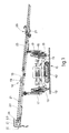
- a pair of structures 13 to support an excavation equipment 14 are hinged on the turret.
- the columns 17 bear at their ends the excavation equipment 14 and by means of the rotation thrust bearings 16 can travel through an angle "alpha" (see Fig.2) in relation to the vertical so as to cover the whole field of drilling.
- the lowest positions A and B of the equipment 14 are those in which any work on the apparatus and drilling materials is carried out advantageously.
- the excavation equipment 14 consists of a support 18 for a drilling head 19 able to run along the support 18.
- the drilling head 19 is equipped in a known manner to actuate a drilling shaft 20 that cooperates with alignment guides 21 suitable to hold and align the shaft 20 on the drilling head 19.
- first vice 23 to clamp the drilling shaft 20 or reinforcement rod 25 and a second vice 24 for the unscrewing of the drilling shaft 20.
- the device 26 may lift advantageously from the ground the reinforcement rod 25 and then thrust it forwards along the whole length of the excavation equipment 14, until the rod is positioned on the device 27 to load reinforcement rods and there awaits its employment (see Figs.3).
- the device 27 to load reinforcement rods consists of a plurality of equal elements spaced apart along the excavation equipment 14.
- Fig.3a shows the reinforcement rod 25 as it is positioned on the alignment guides 21 but might equally well show the drilling shaft 20 in the same position.
- Fig.3b shows two working positions; the lefthand part of the figure indicates the position corresponding to the travel of introduction of the reinforcement rod 25 into the hole made by the drilling shaft 20 by means of the drilling head 19, whereas the righthand part of the figure shows the drilling head 19 after it has carried out its empty return travel so as to take again the drilling shaft 20 parked on the rod-loading device 27 and then to proceed to make a new hole.
- the device 27 to load reinforcement rods 25 consists of a support 28 for connection to the excavation equipment 14 and of a movable arm 29 pivoted at 30 on the support 28.
- the arm 29 may be caused to oscillate about the pivot 30 by a suitable first actuation means, for instance a jack 31.
- the movable arm 29 is a box-wise structure which can lodge within itself a shaped movable sector 32 and a pair of shaped clamping sectors 33.
- the movable sector 32 can rotate about a pivot 34 in relation to the movable arm 29 and in this example is thus moved by a second jack 35 borne on the movable arm 29.
- the movable sector 32 includes two notches 36-136 to lodge the reinforcement rod 25 and the drilling shaft 20 respectively.
- the movable sector 32 is also provided with an element 37 to anchor at least an assembly that actuates the clamping sectors 33, this assembly being a third jack 38 for instance.
- the clamping sectors 33 located on both sides of the movable arm 29 are connected to the third jack 38 at 39 and can rotate on the pivot 34 in relation to the movable arm 29 and the movable sector 32.
- Each clamping sector 33 comprises clamping elements 40-140 which cooperate with the notches 36-136 of the movable sector 32 and with protrusions 41-141 of the movable arm 29 in the various working steps.
- Fig.7a shows the device 27 of the invention with the reinforcement rod 25 in a waiting position. In this position the clamping sectors 33 are actuated and clamp the rod 25 in the notch 36.
- Fig.7b shows the next step of taking the drilling shaft 20 from the drilling head 19 when the drilling of a hole has been completed and the cement agglomerate has been injected.
- the movable arm 29 is rotated by the first jack 31 so as to bring the notch 136 of the movable sector 32 so as to correspond with the drilling shaft 20.
- the third jack 38 is also actuated so as to clamp the drilling shaft 20, which now is located on its trajectory for loading into the drilling head 19.
- Fig.7g in fact shows the step of loading the drilling shaft 20 onto the excavation equipment 14 by means, again, of the first jack 31 actuating the movable arm 29.
- Fig.7h shows the same position as Fig.7a, in which the device 27 is free to take a new reinforcement rod 25 and to begin a new working cycle as described above.
Landscapes
- Engineering & Computer Science (AREA)
- Mining & Mineral Resources (AREA)
- Life Sciences & Earth Sciences (AREA)
- Geology (AREA)
- General Life Sciences & Earth Sciences (AREA)
- Geochemistry & Mineralogy (AREA)
- Mechanical Engineering (AREA)
- Physics & Mathematics (AREA)
- Structural Engineering (AREA)
- Environmental & Geological Engineering (AREA)
- Fluid Mechanics (AREA)
- Excavating Of Shafts Or Tunnels (AREA)
- Earth Drilling (AREA)
- Tumbler Switches (AREA)
- Examining Or Testing Airtightness (AREA)
- Electrical Discharge Machining, Electrochemical Machining, And Combined Machining (AREA)
- Drilling And Exploitation, And Mining Machines And Methods (AREA)
Applications Claiming Priority (2)
| Application Number | Priority Date | Filing Date | Title |
|---|---|---|---|
| IT08349589A IT1236446B (it) | 1989-10-26 | 1989-10-26 | Dispositivo di caricamento armature |
| IT8349589 | 1989-10-26 |
Publications (1)
| Publication Number | Publication Date |
|---|---|
| EP0424733A1 true EP0424733A1 (fr) | 1991-05-02 |
Family
ID=11322587
Family Applications (1)
| Application Number | Title | Priority Date | Filing Date |
|---|---|---|---|
| EP90119457A Withdrawn EP0424733A1 (fr) | 1989-10-26 | 1990-10-11 | Dispositif pour charger des boulons d'ancrage |
Country Status (5)
| Country | Link |
|---|---|
| US (1) | US5116164A (fr) |
| EP (1) | EP0424733A1 (fr) |
| JP (1) | JPH03158592A (fr) |
| KR (1) | KR910008252A (fr) |
| IT (1) | IT1236446B (fr) |
Cited By (7)
| Publication number | Priority date | Publication date | Assignee | Title |
|---|---|---|---|---|
| ES2049590A2 (es) * | 1991-09-30 | 1994-04-16 | Rodio Cimentaciones Especiales | Perforador de taladros para ejecucion de bovedas, tuneles y similares. |
| EP0685631A1 (fr) * | 1994-06-01 | 1995-12-06 | Ing. G. Klemm Bohrtechnik GmbH | Dispositif de retenue pour supporter des tubes de forage |
| EP1167683A1 (fr) * | 2000-06-21 | 2002-01-02 | CASAGRANDE SpA | Ensemble d'introduction des barres d'armature pour les machines de forage |
| EP1167682A1 (fr) * | 2000-06-21 | 2002-01-02 | CASAGRANDE SpA | Machine à forer pour la préparation des excavations dans les tunnels |
| EP0953725A3 (fr) * | 1998-04-30 | 2003-01-22 | TREVI S.p.A. | Dispositif de stockage et chargement des tiges renforcées pour le front et la voûte d'un tunnel |
| US6543555B2 (en) | 2000-03-08 | 2003-04-08 | Casagrande Spa | Automatic loader for drill rods |
| CN104196443A (zh) * | 2014-08-29 | 2014-12-10 | 廊坊景隆重工机械有限公司 | 一种窄机身六臂全液压锚杆锚索钻车 |
Families Citing this family (6)
| Publication number | Priority date | Publication date | Assignee | Title |
|---|---|---|---|---|
| DE4232561A1 (de) * | 1992-09-29 | 1994-03-31 | Bayer Ag | Bekämpfung von Fischparasiten |
| US6085852A (en) | 1995-02-22 | 2000-07-11 | The Charles Machine Works, Inc. | Pipe handling device |
| US6698529B2 (en) * | 2001-04-20 | 2004-03-02 | Oldenburg Cannon, Inc. | Translating turret rock bolter |
| CN104533286B (zh) * | 2014-12-30 | 2016-08-24 | 廊坊景隆重工机械有限公司 | 一种窄机身锚杆锚索钻车 |
| CN111911156A (zh) * | 2020-07-16 | 2020-11-10 | 西安科技大学 | 一种龙门式护盾临时支护及钻锚机器人系统 |
| JP7441133B2 (ja) * | 2020-07-16 | 2024-02-29 | 古河ロックドリル株式会社 | ロックボルト打設装置およびこれを備えるロックボルト打設作業車並びにロックボルトの打設方法 |
Citations (6)
| Publication number | Priority date | Publication date | Assignee | Title |
|---|---|---|---|---|
| US3506075A (en) * | 1966-10-07 | 1970-04-14 | Atlas Copco Ab | Drill string element transfer mechanism |
| FR2402059A1 (fr) * | 1977-08-31 | 1979-03-30 | Atlas Copco Ab | Appareil pour fixer des boulons dans une roche |
| DE2842788A1 (de) * | 1978-09-30 | 1980-04-10 | Secoma | Ankermagazin fuer ein gebirgsankersetzgeraet |
| EP0130969A2 (fr) * | 1983-06-30 | 1985-01-09 | BÖHLER PNEUMATIK INTERNATIONAL GESELLSCHAFT m.b.H. | Dispositif de forage et de pose d'ancrage |
| CH648898A5 (en) * | 1980-07-15 | 1985-04-15 | Sig Schweiz Industrieges | Bolt magazine in a device for mechanically setting rock bolts |
| GB2196884A (en) * | 1986-11-07 | 1988-05-11 | Sig Schweiz Industrieges | Anchor drilling unit |
Family Cites Families (8)
| Publication number | Priority date | Publication date | Assignee | Title |
|---|---|---|---|---|
| US794635A (en) * | 1905-03-18 | 1905-07-11 | Pearson And Son Inc S | Apparatus for erecting tunnels. |
| US2067711A (en) * | 1936-09-16 | 1937-01-12 | Miles I Killmer | Apparatus for erecting tunnel linings |
| US2300167A (en) * | 1940-11-16 | 1942-10-27 | Sullivan Machinery Co | Drilling apparatus |
| SU781361A1 (ru) * | 1977-11-21 | 1980-11-23 | Предприятие П/Я Г-4983 | Устройство дл установки в кровле штанговой крепи |
| SU665096A1 (ru) * | 1978-01-03 | 1979-05-30 | Предприятие П/Я Г-4983 | Устройство дл креплени анкерами кровли горных выработок |
| FR2520800A1 (fr) * | 1982-02-02 | 1983-08-05 | Eimco Secoma | Tourelle de foration et de boulonnage |
| FR2526479A1 (fr) * | 1982-05-06 | 1983-11-10 | Eimco Secoma | Dispositif pour la reception des boulons et leur maintien en cours de pose, sur une tourelle de foration et de boulonnage |
| CN1008382B (zh) * | 1984-11-08 | 1990-06-13 | 林明鸾 | 打桩、拔桩和/或钻孔机 |
-
1989
- 1989-10-26 IT IT08349589A patent/IT1236446B/it active IP Right Grant
-
1990
- 1990-10-11 EP EP90119457A patent/EP0424733A1/fr not_active Withdrawn
- 1990-10-16 US US07/598,135 patent/US5116164A/en not_active Expired - Fee Related
- 1990-10-17 KR KR1019900016531A patent/KR910008252A/ko not_active Withdrawn
- 1990-10-26 JP JP2290606A patent/JPH03158592A/ja active Pending
Patent Citations (6)
| Publication number | Priority date | Publication date | Assignee | Title |
|---|---|---|---|---|
| US3506075A (en) * | 1966-10-07 | 1970-04-14 | Atlas Copco Ab | Drill string element transfer mechanism |
| FR2402059A1 (fr) * | 1977-08-31 | 1979-03-30 | Atlas Copco Ab | Appareil pour fixer des boulons dans une roche |
| DE2842788A1 (de) * | 1978-09-30 | 1980-04-10 | Secoma | Ankermagazin fuer ein gebirgsankersetzgeraet |
| CH648898A5 (en) * | 1980-07-15 | 1985-04-15 | Sig Schweiz Industrieges | Bolt magazine in a device for mechanically setting rock bolts |
| EP0130969A2 (fr) * | 1983-06-30 | 1985-01-09 | BÖHLER PNEUMATIK INTERNATIONAL GESELLSCHAFT m.b.H. | Dispositif de forage et de pose d'ancrage |
| GB2196884A (en) * | 1986-11-07 | 1988-05-11 | Sig Schweiz Industrieges | Anchor drilling unit |
Cited By (7)
| Publication number | Priority date | Publication date | Assignee | Title |
|---|---|---|---|---|
| ES2049590A2 (es) * | 1991-09-30 | 1994-04-16 | Rodio Cimentaciones Especiales | Perforador de taladros para ejecucion de bovedas, tuneles y similares. |
| EP0685631A1 (fr) * | 1994-06-01 | 1995-12-06 | Ing. G. Klemm Bohrtechnik GmbH | Dispositif de retenue pour supporter des tubes de forage |
| EP0953725A3 (fr) * | 1998-04-30 | 2003-01-22 | TREVI S.p.A. | Dispositif de stockage et chargement des tiges renforcées pour le front et la voûte d'un tunnel |
| US6543555B2 (en) | 2000-03-08 | 2003-04-08 | Casagrande Spa | Automatic loader for drill rods |
| EP1167683A1 (fr) * | 2000-06-21 | 2002-01-02 | CASAGRANDE SpA | Ensemble d'introduction des barres d'armature pour les machines de forage |
| EP1167682A1 (fr) * | 2000-06-21 | 2002-01-02 | CASAGRANDE SpA | Machine à forer pour la préparation des excavations dans les tunnels |
| CN104196443A (zh) * | 2014-08-29 | 2014-12-10 | 廊坊景隆重工机械有限公司 | 一种窄机身六臂全液压锚杆锚索钻车 |
Also Published As
| Publication number | Publication date |
|---|---|
| JPH03158592A (ja) | 1991-07-08 |
| US5116164A (en) | 1992-05-26 |
| IT8983495A0 (it) | 1989-10-26 |
| IT8983495A1 (it) | 1991-04-26 |
| IT1236446B (it) | 1993-03-09 |
| KR910008252A (ko) | 1991-05-30 |
Similar Documents
| Publication | Publication Date | Title |
|---|---|---|
| US5116164A (en) | Device to load reinforcement rods | |
| CN112523789B (zh) | 一种双梁锚杆机械化施工装置 | |
| DE2931805A1 (de) | Lafetten- oder mastgefuehrtes bohrgeraet | |
| US5033554A (en) | Well point placement and removal apparatus | |
| US5246313A (en) | Apparatus for forming long and short holes and setting rock bolts | |
| JP3120027B2 (ja) | トンネル用ロックボルト施工装置 | |
| US5129764A (en) | Device to feed reinforcement rods | |
| CN117248522A (zh) | 巨厚粉细砂底层钻孔灌注桩施工装置及方法 | |
| EP2698499B1 (fr) | Procédé et dispositif de fabrication et de mesure d'un trou de forage | |
| KR102667432B1 (ko) | 지반 천공용 케이싱 가이드 장치 | |
| EP0424779A1 (fr) | Dispositif autopropulsé pour forage dans les tunnels | |
| DE3526197A1 (de) | Verfahren und vorrichtung zum einbringen von fertigteiltragelementen, insbesondere stahlbetonstuetzen, in bohrloecher | |
| JPS6231124B2 (fr) | ||
| JP2825362B2 (ja) | ソイルパイル用杭打機 | |
| EP0843048B1 (fr) | Dispositif et méthode pour enfoncer des palplanches | |
| CN109317944B (zh) | 自动定位夹紧装置及钢拱架的装配方法 | |
| US3854295A (en) | Mining equipment | |
| SU897938A1 (ru) | Устройство дл статического испытани грунта | |
| EP2434057A1 (fr) | Équipement pour le percement de trous sécants | |
| CN219219052U (zh) | 一种深基坑边坡支护结构 | |
| JP5130036B2 (ja) | 杭材埋設方法 | |
| KR960004410B1 (ko) | 터널 굴착 방법 | |
| JPH0366828A (ja) | オーガーまたは杭と、穿孔または杭打装置、及び穿孔または杭打法 | |
| JPH01322087A (ja) | 岩盤へのスリツト堀削方法 | |
| JPH0724419Y2 (ja) | 杭埋設機における兼用ホルダー機構 |
Legal Events
| Date | Code | Title | Description |
|---|---|---|---|
| PUAI | Public reference made under article 153(3) epc to a published international application that has entered the european phase |
Free format text: ORIGINAL CODE: 0009012 |
|
| AK | Designated contracting states |
Kind code of ref document: A1 Designated state(s): AT BE CH DE DK ES FR GB GR LI LU NL SE |
|
| 17P | Request for examination filed |
Effective date: 19911007 |
|
| STAA | Information on the status of an ep patent application or granted ep patent |
Free format text: STATUS: THE APPLICATION HAS BEEN WITHDRAWN |
|
| 18W | Application withdrawn |
Withdrawal date: 19920312 |
|
| R18W | Application withdrawn (corrected) |
Effective date: 19920312 |