EP0424742A2 - Convertisseur numérique-analogique à sortie flottante - Google Patents
Convertisseur numérique-analogique à sortie flottante Download PDFInfo
- Publication number
- EP0424742A2 EP0424742A2 EP90119488A EP90119488A EP0424742A2 EP 0424742 A2 EP0424742 A2 EP 0424742A2 EP 90119488 A EP90119488 A EP 90119488A EP 90119488 A EP90119488 A EP 90119488A EP 0424742 A2 EP0424742 A2 EP 0424742A2
- Authority
- EP
- European Patent Office
- Prior art keywords
- transistor
- voltage
- coupled
- circuit
- direct current
- Prior art date
- Legal status (The legal status is an assumption and is not a legal conclusion. Google has not performed a legal analysis and makes no representation as to the accuracy of the status listed.)
- Withdrawn
Links
Images
Classifications
-
- H—ELECTRICITY
- H02—GENERATION; CONVERSION OR DISTRIBUTION OF ELECTRIC POWER
- H02M—APPARATUS FOR CONVERSION BETWEEN AC AND AC, BETWEEN AC AND DC, OR BETWEEN DC AND DC, AND FOR USE WITH MAINS OR SIMILAR POWER SUPPLY SYSTEMS; CONVERSION OF DC OR AC INPUT POWER INTO SURGE OUTPUT POWER; CONTROL OR REGULATION THEREOF
- H02M1/00—Details of apparatus for conversion
- H02M1/08—Circuits specially adapted for the generation of control voltages for semiconductor devices incorporated in static converters
-
- G—PHYSICS
- G05—CONTROLLING; REGULATING
- G05F—SYSTEMS FOR REGULATING ELECTRIC OR MAGNETIC VARIABLES
- G05F1/00—Automatic systems in which deviations of an electric quantity from one or more predetermined values are detected at the output of the system and fed back to a device within the system to restore the detected quantity to its predetermined value or values, i.e. retroactive systems
- G05F1/10—Regulating voltage or current
- G05F1/46—Regulating voltage or current wherein the variable actually regulated by the final control device is DC
- G05F1/468—Regulating voltage or current wherein the variable actually regulated by the final control device is DC characterised by reference voltage circuitry, e.g. soft start, remote shutdown
-
- G—PHYSICS
- G05—CONTROLLING; REGULATING
- G05F—SYSTEMS FOR REGULATING ELECTRIC OR MAGNETIC VARIABLES
- G05F3/00—Non-retroactive systems for regulating electric variables by using an uncontrolled element, or an uncontrolled combination of elements, such element or such combination having self-regulating properties
- G05F3/02—Regulating voltage or current
- G05F3/08—Regulating voltage or current wherein the variable is DC
- G05F3/10—Regulating voltage or current wherein the variable is DC using uncontrolled devices with non-linear characteristics
- G05F3/16—Regulating voltage or current wherein the variable is DC using uncontrolled devices with non-linear characteristics being semiconductor devices
- G05F3/20—Regulating voltage or current wherein the variable is DC using uncontrolled devices with non-linear characteristics being semiconductor devices using diode- transistor combinations
- G05F3/22—Regulating voltage or current wherein the variable is DC using uncontrolled devices with non-linear characteristics being semiconductor devices using diode- transistor combinations wherein the transistors are of the bipolar type only
-
- G—PHYSICS
- G05—CONTROLLING; REGULATING
- G05F—SYSTEMS FOR REGULATING ELECTRIC OR MAGNETIC VARIABLES
- G05F3/00—Non-retroactive systems for regulating electric variables by using an uncontrolled element, or an uncontrolled combination of elements, such element or such combination having self-regulating properties
- G05F3/02—Regulating voltage or current
- G05F3/08—Regulating voltage or current wherein the variable is DC
- G05F3/10—Regulating voltage or current wherein the variable is DC using uncontrolled devices with non-linear characteristics
- G05F3/16—Regulating voltage or current wherein the variable is DC using uncontrolled devices with non-linear characteristics being semiconductor devices
- G05F3/20—Regulating voltage or current wherein the variable is DC using uncontrolled devices with non-linear characteristics being semiconductor devices using diode- transistor combinations
- G05F3/24—Regulating voltage or current wherein the variable is DC using uncontrolled devices with non-linear characteristics being semiconductor devices using diode- transistor combinations wherein the transistors are of the field-effect type only
-
- H—ELECTRICITY
- H02—GENERATION; CONVERSION OR DISTRIBUTION OF ELECTRIC POWER
- H02M—APPARATUS FOR CONVERSION BETWEEN AC AND AC, BETWEEN AC AND DC, OR BETWEEN DC AND DC, AND FOR USE WITH MAINS OR SIMILAR POWER SUPPLY SYSTEMS; CONVERSION OF DC OR AC INPUT POWER INTO SURGE OUTPUT POWER; CONTROL OR REGULATION THEREOF
- H02M1/00—Details of apparatus for conversion
-
- H—ELECTRICITY
- H03—ELECTRONIC CIRCUITRY
- H03M—CODING; DECODING; CODE CONVERSION IN GENERAL
- H03M1/00—Analogue/digital conversion; Digital/analogue conversion
- H03M1/66—Digital/analogue converters
- H03M1/664—Non-linear conversion not otherwise provided for in subgroups of H03M1/66
Definitions
- the present invention relates to a circuit and method for generating and error voltage onto a direct current voltage and, more particularly, to generating a digitally controlled error voltage for incrementally changing a direct current reference voltage in a regulator system.
- a circuit as claimed in claim 1, for producing an output voltage responsive to a current may comprise a first transistor to which a reference voltage is applied to the base thereof while the collector is coupled to source of operating potential, and a controllable current supply coupled to the emitter of the transistor for sinking a current through the transistor the magnitude of which is controlled, the controllable current supply being responsive to applied control signals for incrementally changing the magnitude of the current flowing through the transistor, wherein an output voltage is produced at the emitter of the transistor the magnitude of which is equal to the value of the direct current voltage minus the base-emitter voltage of the transistor, the latter of which is varied as the current through the transistor is changed.
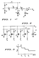
- circuit 10 which is suited to be manufactured in integrated circuit form for generating an output voltage V out that has a small voltage variation induced onto the floating DC reference voltage V in .
- Circuit 10 as will be described by way of one example may operate as a floating digital analog convertor utilizing NPN transistor 12.
- the emitter of transistor 12 is coupled to node 14 to which controlled current supply means 16 is coupled for sinking emitter current I E from the transistor.
- the collector of transistor 12 is coupled to positive supply rail 18 to which V+ is supplied while its base receives the reference voltage V in .
- V in which may be a function of the operating potential V + , is supplied via buffer amplifier 22; the latter of which is coupled between node 24 and the base of transistor 12.
- a resistor divider comprising resistors 26 and 28 produces a reference voltage at node 24. If, for example, the floating digital to analog convertor circuit 10 is used in an automotive alternator regulator, the operating potential that is supplied to rail 18 is a function of the battery voltage of the automobile.
- an error step voltage, waveform 58 (Fig. 3) is generated at node 30 which is induced onto the value of V in .
- I E is controlled in response to receiving digital control signals D1,D2,D3... DN.
- This error voltage can be utilized at one input of comparator 32 while the other input receives a reference voltage V REF to derive a system control signal output 34 whenever the magnitude of V out varies above and below the value of the reference voltage.
- Controllable current supply 16 is shown as including a reference current supply 36 coupled between node 14 and ground reference in which sinks a current I REF .
- Controllable current supply 16 also includes a plurality MOS transistors 44, 48, 52 ... 56N each of which have their drain electrodes coupled to node 14 and their source electrodes coupled to ground supply.
- An operating potential, V is supplied to conductor 40 which in turn is coupled to the individual gate electrodes of the MOS transistors via respective resistors 42, 46, 50 ...56N.
- the gate electrodes of the MOS transistors are also adapted to receive individual digital control signals D1, D2, D3 ...DN.
- V BE will increase or decrease by 60 millivolts per decade of change in emitter current as is understood.
- the magnitude of I E at the threshold value is produced by having all of the MOS transistors turned on in parallel to the current I REF . These MOS transistors are turned on if the respective digital signals D1 through DN are at a logic one. As D1 goes low, transistor 42 is turned off which decreases the magnitude of I E and hence V out . Similarly, as the digital control signals D2, D3 etc. go low, V out is incrementally reduced (Fig. 3). Thus, a small error voltage is induced onto the larger direct current voltage V in . This can been seen as the stair step waveform of V out . It is understood that the currents flowing in the MOS transistors and I REF must track one another.
- V REF and V in may be interchanged and the principle of the present invention is not changed..Furthermore, it should be understood that the MOS transistors of controllable current supply could be bipolar transistors.
Landscapes
- Engineering & Computer Science (AREA)
- Physics & Mathematics (AREA)
- Microelectronics & Electronic Packaging (AREA)
- Nonlinear Science (AREA)
- Electromagnetism (AREA)
- General Physics & Mathematics (AREA)
- Radar, Positioning & Navigation (AREA)
- Automation & Control Theory (AREA)
- Theoretical Computer Science (AREA)
- Power Engineering (AREA)
- Analogue/Digital Conversion (AREA)
- Control Of Electrical Variables (AREA)
Applications Claiming Priority (2)
| Application Number | Priority Date | Filing Date | Title |
|---|---|---|---|
| US07/427,552 US4961045A (en) | 1989-10-27 | 1989-10-27 | Floating output digital to analog converter |
| US427552 | 1989-10-27 |
Publications (2)
| Publication Number | Publication Date |
|---|---|
| EP0424742A2 true EP0424742A2 (fr) | 1991-05-02 |
| EP0424742A3 EP0424742A3 (en) | 1992-03-25 |
Family
ID=23695356
Family Applications (1)
| Application Number | Title | Priority Date | Filing Date |
|---|---|---|---|
| EP19900119488 Withdrawn EP0424742A3 (en) | 1989-10-27 | 1990-10-11 | Floating output digital to analog converter |
Country Status (4)
| Country | Link |
|---|---|
| US (1) | US4961045A (fr) |
| EP (1) | EP0424742A3 (fr) |
| JP (1) | JPH03151721A (fr) |
| KR (1) | KR910008924A (fr) |
Cited By (1)
| Publication number | Priority date | Publication date | Assignee | Title |
|---|---|---|---|---|
| EP0623866A3 (fr) * | 1993-05-07 | 1995-01-11 | Siemens Ag | Dispositif source de courant pour produire des courants de références multiples. |
Families Citing this family (4)
| Publication number | Priority date | Publication date | Assignee | Title |
|---|---|---|---|---|
| US5055847A (en) * | 1991-02-19 | 1991-10-08 | Motorola, Inc. | Differential sensing current-steering analog-to-digital converter |
| US5260643A (en) * | 1992-07-16 | 1993-11-09 | National Semiconductor Corporation | Programmable reference voltage generator |
| CN100589307C (zh) * | 2007-02-09 | 2010-02-10 | 朋程科技股份有限公司 | 适用于多种车用发电机的调节器 |
| US9503121B2 (en) * | 2014-10-17 | 2016-11-22 | Infineon Technologies Ag | Very high dynamic-range switched capacitor ADC with large input impedance for applications tolerating increased distortion and noise at large input signal levels |
Family Cites Families (6)
| Publication number | Priority date | Publication date | Assignee | Title |
|---|---|---|---|---|
| JPS5463662A (en) * | 1977-10-28 | 1979-05-22 | Nec Corp | Current supply circuit |
| US4292625A (en) * | 1979-07-12 | 1981-09-29 | Advanced Micro Devices, Inc. | Monolithic digital-to-analog converter |
| JPS5672350A (en) * | 1979-11-19 | 1981-06-16 | Advantest Corp | Variable current source |
| US4354159A (en) * | 1981-02-02 | 1982-10-12 | Rockwell International Corporation | Prescription attenuator having cascaded L-pad sections |
| US4414501A (en) * | 1981-05-26 | 1983-11-08 | General Electric Company | Programmable signal amplitude control circuits |
| JP2577897B2 (ja) * | 1986-10-31 | 1997-02-05 | 日本テキサス・インスツルメンツ 株式会社 | 定電圧電源回路 |
-
1989
- 1989-10-27 US US07/427,552 patent/US4961045A/en not_active Expired - Fee Related
-
1990
- 1990-10-11 EP EP19900119488 patent/EP0424742A3/en not_active Withdrawn
- 1990-10-24 KR KR1019900017033A patent/KR910008924A/ko not_active Withdrawn
- 1990-10-26 JP JP2287383A patent/JPH03151721A/ja active Pending
Cited By (1)
| Publication number | Priority date | Publication date | Assignee | Title |
|---|---|---|---|---|
| EP0623866A3 (fr) * | 1993-05-07 | 1995-01-11 | Siemens Ag | Dispositif source de courant pour produire des courants de références multiples. |
Also Published As
| Publication number | Publication date |
|---|---|
| KR910008924A (ko) | 1991-05-31 |
| JPH03151721A (ja) | 1991-06-27 |
| EP0424742A3 (en) | 1992-03-25 |
| US4961045A (en) | 1990-10-02 |
Similar Documents
| Publication | Publication Date | Title |
|---|---|---|
| US4346343A (en) | Power control means for eliminating circuit to circuit delay differences and providing a desired circuit delay | |
| US4893228A (en) | High-efficiency programmable power supply | |
| EP0620515B1 (fr) | Source de tension de référence du type Bandgap | |
| US4808907A (en) | Current regulator and method | |
| US4642551A (en) | Current to voltage converter circuit | |
| KR0143362B1 (ko) | 넓은 전압 범위에서 동작 가능한 판정 회로 | |
| US4706010A (en) | Linear solar array voltage control system | |
| US4658205A (en) | Reference voltage generating circuit | |
| US4556805A (en) | Comparator circuit having hysteresis voltage substantially independent of variation in power supply voltage | |
| US4961045A (en) | Floating output digital to analog converter | |
| US4686395A (en) | Current switching type logic circuit | |
| US4888589A (en) | Digital-to-analog converter with diode control | |
| JPH0315381B2 (fr) | ||
| GB2024550A (en) | Integrated driver circuits | |
| US4716359A (en) | Output stage control circuit | |
| EP0359171B1 (fr) | Circuit pour déterminer la forme d'onde de courant d'un transistor | |
| KR860009555A (ko) | 저전압 디지탈 투 아날로그 변환기용 입력레벨 시프트 회로 | |
| EP0003260A1 (fr) | Convertisseur numérique-analogue à logique à injection intégré utilisant une régulation par contre-réaction et son procédé de fabrication | |
| US4485352A (en) | Current amplifier | |
| US4758820A (en) | Semiconductor circuit | |
| US4095127A (en) | Transistor base drive regulator | |
| US5939907A (en) | Low power, high speed driving circuit for driving switching elements | |
| US4366447A (en) | Push-pull amplifier circuit | |
| US6459396B2 (en) | Electric current switch circuit and D/A converter using same | |
| JPH0628013B2 (ja) | レギュレ−タ回路 |
Legal Events
| Date | Code | Title | Description |
|---|---|---|---|
| PUAI | Public reference made under article 153(3) epc to a published international application that has entered the european phase |
Free format text: ORIGINAL CODE: 0009012 |
|
| AK | Designated contracting states |
Kind code of ref document: A2 Designated state(s): DE FR GB IT |
|
| PUAL | Search report despatched |
Free format text: ORIGINAL CODE: 0009013 |
|
| AK | Designated contracting states |
Kind code of ref document: A3 Designated state(s): DE FR GB IT |
|
| 17P | Request for examination filed |
Effective date: 19920831 |
|
| 17Q | First examination report despatched |
Effective date: 19940202 |
|
| STAA | Information on the status of an ep patent application or granted ep patent |
Free format text: STATUS: THE APPLICATION IS DEEMED TO BE WITHDRAWN |
|
| 18D | Application deemed to be withdrawn |
Effective date: 19940614 |