EP0424798A2 - Appareil pour la fabrication des plaques de circuit imprimÀ© ou multicouche avec des trous métallisés en travers - Google Patents
Appareil pour la fabrication des plaques de circuit imprimÀ© ou multicouche avec des trous métallisés en travers Download PDFInfo
- Publication number
- EP0424798A2 EP0424798A2 EP90119966A EP90119966A EP0424798A2 EP 0424798 A2 EP0424798 A2 EP 0424798A2 EP 90119966 A EP90119966 A EP 90119966A EP 90119966 A EP90119966 A EP 90119966A EP 0424798 A2 EP0424798 A2 EP 0424798A2
- Authority
- EP
- European Patent Office
- Prior art keywords
- module
- circuit boards
- treatment liquid
- takes place
- modules
- Prior art date
- Legal status (The legal status is an assumption and is not a legal conclusion. Google has not performed a legal analysis and makes no representation as to the accuracy of the status listed.)
- Withdrawn
Links
- 238000004519 manufacturing process Methods 0.000 title claims abstract description 10
- 239000000178 monomer Substances 0.000 claims abstract description 16
- 238000010924 continuous production Methods 0.000 claims abstract description 9
- 230000001590 oxidative effect Effects 0.000 claims abstract description 7
- 239000007864 aqueous solution Substances 0.000 claims abstract description 6
- 239000007788 liquid Substances 0.000 claims description 85
- 238000000034 method Methods 0.000 claims description 71
- 230000008569 process Effects 0.000 claims description 60
- 238000011010 flushing procedure Methods 0.000 claims description 10
- 239000000243 solution Substances 0.000 claims description 8
- 239000000126 substance Substances 0.000 claims description 8
- 239000003960 organic solvent Substances 0.000 claims description 7
- XLYOFNOQVPJJNP-UHFFFAOYSA-N water Substances O XLYOFNOQVPJJNP-UHFFFAOYSA-N 0.000 claims description 7
- 238000005554 pickling Methods 0.000 claims description 6
- 230000003750 conditioning effect Effects 0.000 claims description 5
- 239000008237 rinsing water Substances 0.000 claims description 5
- 238000002604 ultrasonography Methods 0.000 claims description 5
- 238000005868 electrolysis reaction Methods 0.000 claims description 3
- 239000000463 material Substances 0.000 claims description 3
- 238000006116 polymerization reaction Methods 0.000 claims description 3
- 229920001343 polytetrafluoroethylene Polymers 0.000 claims description 3
- 239000004810 polytetrafluoroethylene Substances 0.000 claims description 3
- 239000002253 acid Substances 0.000 claims description 2
- 238000010306 acid treatment Methods 0.000 claims description 2
- 238000000151 deposition Methods 0.000 claims description 2
- 238000009434 installation Methods 0.000 claims 2
- 238000001465 metallisation Methods 0.000 abstract description 4
- 230000001143 conditioned effect Effects 0.000 abstract description 2
- 239000003054 catalyst Substances 0.000 description 13
- QAOWNCQODCNURD-UHFFFAOYSA-N Sulfuric acid Chemical compound OS(O)(=O)=O QAOWNCQODCNURD-UHFFFAOYSA-N 0.000 description 9
- 230000003647 oxidation Effects 0.000 description 7
- 238000007254 oxidation reaction Methods 0.000 description 7
- WSFSSNUMVMOOMR-UHFFFAOYSA-N Formaldehyde Chemical compound O=C WSFSSNUMVMOOMR-UHFFFAOYSA-N 0.000 description 6
- RYGMFSIKBFXOCR-UHFFFAOYSA-N Copper Chemical compound [Cu] RYGMFSIKBFXOCR-UHFFFAOYSA-N 0.000 description 5
- 229910052802 copper Inorganic materials 0.000 description 5
- 239000010949 copper Substances 0.000 description 5
- 238000007654 immersion Methods 0.000 description 5
- 229920001940 conductive polymer Polymers 0.000 description 4
- HEMHJVSKTPXQMS-UHFFFAOYSA-M Sodium hydroxide Chemical compound [OH-].[Na+] HEMHJVSKTPXQMS-UHFFFAOYSA-M 0.000 description 3
- 238000009825 accumulation Methods 0.000 description 3
- 239000008139 complexing agent Substances 0.000 description 3
- 238000005530 etching Methods 0.000 description 3
- 230000003993 interaction Effects 0.000 description 3
- 238000007747 plating Methods 0.000 description 3
- 230000002378 acidificating effect Effects 0.000 description 2
- 238000004140 cleaning Methods 0.000 description 2
- 230000003749 cleanliness Effects 0.000 description 2
- 239000004020 conductor Substances 0.000 description 2
- 238000010276 construction Methods 0.000 description 2
- 230000001627 detrimental effect Effects 0.000 description 2
- 229910000510 noble metal Inorganic materials 0.000 description 2
- 239000002244 precipitate Substances 0.000 description 2
- 239000007921 spray Substances 0.000 description 2
- 238000005406 washing Methods 0.000 description 2
- LFQSCWFLJHTTHZ-UHFFFAOYSA-N Ethanol Chemical compound CCO LFQSCWFLJHTTHZ-UHFFFAOYSA-N 0.000 description 1
- 206010016275 Fear Diseases 0.000 description 1
- 239000004809 Teflon Substances 0.000 description 1
- 229920006362 Teflon® Polymers 0.000 description 1
- 230000009471 action Effects 0.000 description 1
- 230000006978 adaptation Effects 0.000 description 1
- 239000012670 alkaline solution Substances 0.000 description 1
- 230000009286 beneficial effect Effects 0.000 description 1
- 230000015572 biosynthetic process Effects 0.000 description 1
- 238000009835 boiling Methods 0.000 description 1
- 230000003197 catalytic effect Effects 0.000 description 1
- 238000006243 chemical reaction Methods 0.000 description 1
- 238000011109 contamination Methods 0.000 description 1
- 230000008878 coupling Effects 0.000 description 1
- 238000010168 coupling process Methods 0.000 description 1
- 238000005859 coupling reaction Methods 0.000 description 1
- 230000000694 effects Effects 0.000 description 1
- 238000009713 electroplating Methods 0.000 description 1
- 230000007613 environmental effect Effects 0.000 description 1
- 238000000605 extraction Methods 0.000 description 1
- 230000002349 favourable effect Effects 0.000 description 1
- 239000013505 freshwater Substances 0.000 description 1
- 230000006870 function Effects 0.000 description 1
- 239000007789 gas Substances 0.000 description 1
- 238000009776 industrial production Methods 0.000 description 1
- 238000012423 maintenance Methods 0.000 description 1
- WSFSSNUMVMOOMR-NJFSPNSNSA-N methanone Chemical compound O=[14CH2] WSFSSNUMVMOOMR-NJFSPNSNSA-N 0.000 description 1
- 238000002156 mixing Methods 0.000 description 1
- 238000012544 monitoring process Methods 0.000 description 1
- 239000007800 oxidant agent Substances 0.000 description 1
- 239000012286 potassium permanganate Substances 0.000 description 1
- 239000010970 precious metal Substances 0.000 description 1
- 238000001556 precipitation Methods 0.000 description 1
- 239000000758 substrate Substances 0.000 description 1
Images

Classifications
-
- H—ELECTRICITY
- H05—ELECTRIC TECHNIQUES NOT OTHERWISE PROVIDED FOR
- H05K—PRINTED CIRCUITS; CASINGS OR CONSTRUCTIONAL DETAILS OF ELECTRIC APPARATUS; MANUFACTURE OF ASSEMBLAGES OF ELECTRICAL COMPONENTS
- H05K3/00—Apparatus or processes for manufacturing printed circuits
- H05K3/40—Forming printed elements for providing electric connections to or between printed circuits
- H05K3/42—Plated through-holes or plated via connections
-
- H—ELECTRICITY
- H05—ELECTRIC TECHNIQUES NOT OTHERWISE PROVIDED FOR
- H05K—PRINTED CIRCUITS; CASINGS OR CONSTRUCTIONAL DETAILS OF ELECTRIC APPARATUS; MANUFACTURE OF ASSEMBLAGES OF ELECTRICAL COMPONENTS
- H05K3/00—Apparatus or processes for manufacturing printed circuits
- H05K3/0085—Apparatus for treatments of printed circuits with liquids not provided for in groups H05K3/02 - H05K3/46; conveyors and holding means therefor
- H05K3/0088—Apparatus for treatments of printed circuits with liquids not provided for in groups H05K3/02 - H05K3/46; conveyors and holding means therefor for treatment of holes
-
- H—ELECTRICITY
- H05—ELECTRIC TECHNIQUES NOT OTHERWISE PROVIDED FOR
- H05K—PRINTED CIRCUITS; CASINGS OR CONSTRUCTIONAL DETAILS OF ELECTRIC APPARATUS; MANUFACTURE OF ASSEMBLAGES OF ELECTRICAL COMPONENTS
- H05K3/00—Apparatus or processes for manufacturing printed circuits
- H05K3/40—Forming printed elements for providing electric connections to or between printed circuits
- H05K3/42—Plated through-holes or plated via connections
- H05K3/423—Plated through-holes or plated via connections characterised by electroplating method
- H05K3/424—Plated through-holes or plated via connections characterised by electroplating method by direct electroplating
-
- H—ELECTRICITY
- H05—ELECTRIC TECHNIQUES NOT OTHERWISE PROVIDED FOR
- H05K—PRINTED CIRCUITS; CASINGS OR CONSTRUCTIONAL DETAILS OF ELECTRIC APPARATUS; MANUFACTURE OF ASSEMBLAGES OF ELECTRICAL COMPONENTS
- H05K2201/00—Indexing scheme relating to printed circuits covered by H05K1/00
- H05K2201/03—Conductive materials
- H05K2201/032—Materials
- H05K2201/0329—Intrinsically conductive polymer [ICP]; Semiconductive polymer
-
- H—ELECTRICITY
- H05—ELECTRIC TECHNIQUES NOT OTHERWISE PROVIDED FOR
- H05K—PRINTED CIRCUITS; CASINGS OR CONSTRUCTIONAL DETAILS OF ELECTRIC APPARATUS; MANUFACTURE OF ASSEMBLAGES OF ELECTRICAL COMPONENTS
- H05K2203/00—Indexing scheme relating to apparatus or processes for manufacturing printed circuits covered by H05K3/00
- H05K2203/07—Treatments involving liquids, e.g. plating, rinsing
- H05K2203/0779—Treatments involving liquids, e.g. plating, rinsing characterised by the specific liquids involved
- H05K2203/0783—Using solvent, e.g. for cleaning; Regulating solvent content of pastes or coatings for adjusting the viscosity
-
- H—ELECTRICITY
- H05—ELECTRIC TECHNIQUES NOT OTHERWISE PROVIDED FOR
- H05K—PRINTED CIRCUITS; CASINGS OR CONSTRUCTIONAL DETAILS OF ELECTRIC APPARATUS; MANUFACTURE OF ASSEMBLAGES OF ELECTRICAL COMPONENTS
- H05K2203/00—Indexing scheme relating to apparatus or processes for manufacturing printed circuits covered by H05K3/00
- H05K2203/07—Treatments involving liquids, e.g. plating, rinsing
- H05K2203/0779—Treatments involving liquids, e.g. plating, rinsing characterised by the specific liquids involved
- H05K2203/0786—Using an aqueous solution, e.g. for cleaning or during drilling of holes
- H05K2203/0796—Oxidant in aqueous solution, e.g. permanganate
-
- H—ELECTRICITY
- H05—ELECTRIC TECHNIQUES NOT OTHERWISE PROVIDED FOR
- H05K—PRINTED CIRCUITS; CASINGS OR CONSTRUCTIONAL DETAILS OF ELECTRIC APPARATUS; MANUFACTURE OF ASSEMBLAGES OF ELECTRICAL COMPONENTS
- H05K2203/00—Indexing scheme relating to apparatus or processes for manufacturing printed circuits covered by H05K3/00
- H05K2203/12—Using specific substances
- H05K2203/122—Organic non-polymeric compounds, e.g. oil, wax or thiol
Definitions
- Electroless copper baths of this type contain complexing agents and usually formaldehyde.
- the use of noble metal catalysts, like that of complexing agents and formaldehyde is not very desirable for environmental reasons.
- the maintenance and bath monitoring of the copper-plating process without external current is complex and complicated. Even if you work carefully, there is always the danger that one of the bathrooms may "accidentally" fail.
- the object of the present invention is to design a system of the type mentioned at the outset in such a way that large numbers of items can be achieved in industrial production.
- Modular systems are known per se in the industrial manufacture of printed circuit boards for other tasks, through which the printed circuit boards are moved in a horizontal continuous process on a conveyor system.
- the method known from DE-PS 38 06 884 is primarily implemented in a continuous continuous process.
- the "growth" of the first monomer layer on the wall of the boreholes is a dynamically very delicate process.
- relative movements between the circuit board and the treatment liquid must be avoided in this phase, that is to say that the circuit boards must actually stand still during contact with the solution containing the monomers.
- this presumption is not correct, that is, contrary to the fears, a carefully guided relative movement of the circuit boards with respect to the treatment liquid is the success is not only not detrimental but even beneficial.
- a rinsing module is connected between the successive modules in which processes a, b, c take place, in which the circuit boards are sprayed with rinsing water on both sides, but with the modules in which processes c and d run directly touch each other with their output station or input station without the intermediary of a rinsing module.
- the use of rinsing modules between successive treatment modules follows from the experience gained with continuous continuous processes in other manufacturing areas. However, it was not easy to foresee that a rinsing process between the modules, in which the surfaces to be coated are coated with monomers and the monomers are then polymerized into the electrically conductive layer, was rather harmful.
- a drop flight between the last two modules of the system discussed here is particularly critical. As already mentioned above, these are preferably not separated from one another by a dishwasher. It is therefore preferred here that the air space in the output station of the module in which process c takes place and the air space in the input station of the module in which process d takes place can be supplied with supply air. This supply air in the intermediate output and input stations then, together with the negative pressure in the extracted modules, ensures that an air flow can only return from the output or input station to the associated module, but never cross from module to module. Droplets contained in the air streams cannot pass from module to module in this way.
- the rinsing modules are preferably designed as cascade dishwashers with a plurality of separate chambers through which the rinsing water flows, counter to the direction of movement of the printed circuit boards.
- cascade dishwashers which are known per se, the cleaning action is particularly good with low flushing water consumption.
- the module in which process d takes place should be followed by a rinsing and decapitation module in which the printed circuit boards are sprayed on both sides with dilute acid.
- the polymerization that takes place in the last module of the system results in a voluminous, blackish precipitate that easily detaches from the metallic surfaces of the printed circuit boards. This precipitate must be dissolved and / or removed, which is preferably done in this rinsing and pickling module.
- the measure used to reduce the chemical consumption is that the treatment liquid in the module in which process b is carried out can be circulated via an electrolysis cell in which the treatment liquid is regenerated.
- This treatment liquid is generally an alkaline permanganate solution. As is known, the permanganate is returned to a lower oxidation state in the oxidation process and can be oxidized again electrolytically.
- the printed circuit boards should be passed through the various modules at least in regions below the level of the treatment liquid located there.
- the modules in which processes a to d take place each have a sump for the treatment liquid and a container arranged on the path of movement of the printed circuit boards, a pump being provided in each case so that the treatment liquid flows out of the sump in the container pumps that in the container in dynamic equilibrium between supply and overflow a level of the treatment liquid that is above the path of movement of the circuit boards.
- the circuit boards are therefore not simply pulled through a stationary treatment liquid, but in interaction brought with a treatment liquid that is constantly renewed.
- this constant renewal means an additional relative movement between the circuit board and the treatment liquid.
- the treatment liquid is introduced into the lower region of the container via distributor pipes, and that a shielding plate is arranged between the distributor pipes and the path of movement of the printed circuit boards, the edges of which up to the side walls of the container. Turbulence, which could arise from the introduction of treatment liquid into the container, essentially takes place below the shielding plate.
- the treatment liquid then flows up through the gaps between the edges of the shielding plate and the side walls of the container in a controlled flow process.
- the circuit boards move above the shielding plates in a calm, defined flow pattern.
- pairs of rollers and / or pairs of rollers / rollers can be arranged, the circuit boards being passed between the partners of the pairs.
- Rollers are understood to mean components whose axial extent extends essentially over the entire width of the container.
- Rollers are relatively short components in the axial direction, of which several are always arranged next to one another and at an axial distance across the width of the container.
- a pair of rollers / rollers therefore contains a roller extending over the entire width of the container on one side of the path of movement of the circuit board, but a plurality of rollers which are arranged at a distance from one another on the opposite side of the path of movement.
- the roller or roller located on top in a pair serves as accumulation rollers or accumulation rollers, on which the treatment liquid can accumulate beyond the path of movement of the printed circuit boards.
- the accumulation effect is less here than at the opposite end, where the top partner of the pair is a continuous roller.
- the treatment liquid jammed between the pair of rollers and the pair of rollers / rollers receives a main flow direction in the direction of the pair of rollers / rollers. In this way, a defined movement of the treatment liquid is forced in this crucial area.
- rollers in the pair of rollers at the entrance to the container should be made of poorly wettable material, preferably PTFE. In this way it is prevented that the rollers carry over treatment liquid from the interior of the container to the outside in an uncontrolled manner or even splash it during their rotation. As already mentioned several times, this would lead to uncontrolled contacts between the circuit boards and the treatment liquid before the time lead to whom this contact is then actually desired.
- a filter can be assigned to one or more modules in which one of the processes a to d takes place, via which the treatment liquid of this module is circulated. From what has been said above, it should be clear that the cleanliness of the treatment liquid is important for the result achieved. This cleanliness is guaranteed by the continuous circulation of the treatment liquid through the filter.
- one or more of the modules in which one of the processes a to d takes place is assigned an ultrasound device via which the treatment liquid in this module can be subjected to ultrasound.
- an embodiment of the invention is characterized in that one or more of the modules in which one of the processes a to d takes place is assigned a nozzle in the vicinity of the path of movement of the printed circuit boards, which forces the boreholes to be flooded with the aid of pressure and / or brings about negative pressure.
- dwell times are achieved in a known manner by mutually coordinating the speed of the conveyor system and the length of the individual modules.
- the ratio of the dwell times in the last two modules of the system according to the invention has proven to be of particular importance. Regardless of the absolute size of these dwell times, it is advisable if the module in which process d takes place is approximately half as long as the module in which process c takes place. This means that the length of stay in the last module should always be about half as long as the length of stay in the penultimate module.
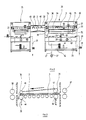
- FIG. 1 shows a section of a plant for the production of plated-through circuit boards. This is the area which, when a conductive layer is achieved, on the jacket surfaces of the holes drilled in the circuit boards. This first layer then serves for the further external currentless or electrolytic-galvanic build-up of a relatively thick metallic (generally copper) layer. The corresponding system part is not shown in Figure 1; they would join on the left.
- there are still machines that deal with the formation of the line pattern, so that at the end of the overall system, printed circuit boards with a finished conductor pattern emerge on both sides, the conductor pattern being electrically connected to one another via different holes on both sides ( "plated through”.
- the various drill holes are made in the circuit boards, the drill holes are then mechanically deburred (brushed); Contamination from the lateral surfaces of the holes is removed.
- a first etching (“micro-etching") is used to remove oxide layers and to improve adhesion.
- the printed circuit boards pretreated in this way enter the right side of the system area shown in FIG. 1 and pass through them in the direction of the arrow drawn above the system.
- the system has a modular structure, ie it is composed of individual, standardized machines, in each of which one process step is carried out.
- the modules are matched to one another in such a way that they can be assembled as a modular system to form an overall system.
- each module is a fully functional machine and is generally also capable of being traded independently.
- module 1 which is located on the far right in FIG. 1, the pretreated, that is to say in particular provided with boreholes, deburred and cleaned circuit boards are "conditioned". “Conditioning” here means a treatment with an aqueous alkaline solution of an organic solvent, which in particular puts the lateral surfaces of the boreholes in a state in which the layer applied in the subsequent modules is guaranteed to adhere.
- the printed circuit boards are conveyed through the various modules on a roller conveyor system 2, which connects directly to one another at the various joints of the individual modules and can either be driven separately for each individual module or can also be moved from a common source by means of a corresponding coupling between the modules.
- the printed circuit board which is identified by the reference number 3 in FIG. 1, moves below the corresponding liquid level.
- NaOH is fed via a line 4
- the above-mentioned organic solvent is fed to the module 1 via a line 5
- used treatment liquid can be removed from the module 1 via a further line 6.
- the printed circuit boards 3 treated in module 1 enter a flushing module 7, where they are sprayed on the conveyor system 2 from above and below with flushing water.
- the rinsing module 7 is constructed like a cascade. For this purpose, it is divided into three individual compartments 7a to 7c, each of which has a separate sump. Each sump is assigned its own pump 8a, 8b, 8c, which pumps the flushing water up to nozzle sticks along the path of movement of the printed circuit boards 3. Fresh water is fed to the washing module 7 via the line 9 at the end at which the cleaned printed circuit boards 3 leave the washing module 7.
- the rinsing water flows from the compartment 7a of the rinsing module 7 to the compartments 7b and 7c in an overflow process against the direction of movement of the printed circuit boards 3 and is discharged thinly via the line 10. This countercurrent process ensures that the circuit boards 3 within the flushing module 7 come into contact with the cleanest flushing water last.
- the circuit boards 3 are introduced from the flushing module 7 into an oxidation module 11 by the conveyor system 2.
- the outer surfaces of the contact holes are treated with an oxidizing liquid, a process step which is of great importance for the adhesion of the electrically conductive film to be applied in the subsequent modules.
- An alkaline potassium permanganate solution is used as the treatment liquid. This is fed in via line 12 and discharged via line 13.
- the treatment liquid within the oxidation module 11 is circulated via an electrolysis cell 14 and continuously regenerated, so that the chemical consumption within the oxidation module 11 is kept at the lowest possible value.
- the printed circuit boards 3 which are subjected to the oxidation treatment are again moved through a rinsing module 15, the structure of which corresponds to the rinsing module 7 and the rinsing water also flows through in a cascade manner in a countercurrent process.
- a rinsing module 7 the structure of which corresponds to the rinsing module 7 and the rinsing water also flows through in a cascade manner in a countercurrent process.
- the printed circuit boards 3 enter a module 16, which is referred to as the “catalyst module” based on the methods previously used.
- the term "catalyst” is not entirely appropriate in the present process. Rather, the module 16 takes the first step on the way to a conductive layer on the lateral surfaces of the boreholes.
- a treatment liquid is introduced into the catalyst module 16 via a line 17, which can be removed again via a line 18.
- the treatment liquid is an aqueous solution of an organic monomer with a certain amount of organic solvent, preferably a high-boiling alcohol.
- DE-PS 38 06 884 provides information on the type of monomers.
- the monomers contained in this treatment liquid are (among other things) deposited on the lateral surface of the boreholes and thus form a thin layer which, however, is not yet conductive in this state.
- the printed circuit boards 3 pass from the output station 19 of the catalyst module 16 into the input station 20 of a so-called “fixing module” 21.
- the monomers are polymerized in the layer that is on the printed circuit boards 3 in the module 16 has discontinued.
- a uniformly conductive polymer film forms on the only little adheres to the metallic surfaces of the printed circuit boards 3 and detaches from them as dark precipitation.
- the lateral surfaces of the boreholes remain lined with the electrically conductive polymer film in the desired manner.
- the "fixation" in the fixation module 21 takes place in an acidic medium, possibly with the addition of a small amount of oxidizing agent.
- the acidic medium generally an approximately five percent sulfuric acid, is fed to the fixing module 21 via line 22 and removed via line 23.
- the treatment liquid here is not water, but five percent sulfuric acid, which is also cascaded in a countercurrent process through the various chambers of the rinsing and pickling module 24.
- the five percent sulfuric acid is formed by mixing in the left-most compartment in FIG. 1 of the rinsing and pickling module 24 of water and concentrated sulfuric acid, the tanks 25 and 26 being removed.
- FIG. 2 shows the catalyst module 16 and the ones following it on a larger scale and in more detail Fixation module 21.
- an essential feature in the treatment of the printed circuit boards 3 in the individual modules is that they are moved through the corresponding module below the level of the treatment liquid, ie completely immersed in it. This is achieved by means of a construction which is now described with reference to FIG. 2 for the catalyst module 16, but can be found in the same way in all modules of the system.
- the module 16 comprises a sump 26 for the treatment liquid in the lower region.
- the treatment liquid is fed to this by means of a pump 27 via the line 17 already mentioned above.
- a pump 28 removes treatment liquid from the sump 26 and directs it via a valve 29 and a flow meter 30 into a container 31 which is arranged directly below the delivery system 2.
- the treatment liquid is dispensed into the container 3 via two distributor pipes 32 and 33. These are located below a shielding plate 34, which runs parallel to the bottom of the container 31 or to the conveyor system 2.
- the edges of the shielding plate 34 extend close to the walls of the container 31, so that the treatment liquid can only penetrate upward in these edge regions. The result of this is that the printed circuit boards 3 can move on the conveyor system 2 above the shielding plate 34 in a treatment liquid which is practically not disturbed by the addition via the distributor pipes 32, 33, and in particular contains no turbulence.
- the printed circuit boards 3 enter the treatment liquid accumulated in the container 31 through a pair of rollers 35.
- the pair of rollers 35 and the pair of rollers / rollers 36 represent a defined "leak" for the container 31, via which treatment liquid can escape from the container 31 to the extent that it is newly supplied by the pump 28 and via the distributor pipes 32 and 33 becomes.
- a mirror of the treatment liquid is maintained in a stationary manner, which lies above the conveyor system 2 and the printed circuit boards 3 moved on it.
- the treatment liquid emerging through the gap of the pair of rollers 35 or the pair of rollers / rollers 36 returns to the sump 26 of the module 16 and is again drawn in by the pump 28.
- the printed circuit boards 3 each pass through a pair of squeeze rollers 37 and 38, which largely removes any treatment liquid still adhering to the printed circuit boards 3 and thus reduces the carryover of treatment liquid into downstream modules.
- an ultrasound transmitter 41 is located below the path of movement of the printed circuit boards 3, by means of which the effectiveness of the treatment liquid can be increased.
- a forced flow through the boreholes is arranged here, which presses treatment liquid through the boreholes under pressure and / or vacuum.
- a filter 42 is accommodated in the sump 26 of the module 16, through which the filter located in the sump 26 is continuous Treatment liquid is circulated by means of a pump 43.
- a manometer 44 indicates when the filter 42 is clogged.
- FIG. 2 shows the line 18 already mentioned above, via which the treatment liquid can be removed from the module 16.
- line 18 in all lines which supply or remove treatment liquid to the modules, there is a solenoid valve 44.
- This solenoid valve 44 is controlled in a known manner and is not the subject of the present invention.
- rollers and rollers can also have the same diameter.
- a “roller” is understood here to mean an object whose axial dimension extends over the entire width of the container 31, while a “roller” has a relatively small axial dimension. Where rolls, that is to say circles with a small diameter, are shown in FIG. 3, this is to be understood in such a way that several rolls are arranged one behind the other on an axis at a distance from one another.
- the pair of rollers / rollers 36 thus consists of a lower roller 44, which extends across the entire dimension of the container 31 perpendicular to the plane of the drawing, and a plurality of coaxial rollers 45 opposite it.
- the pair of rollers 35 on the other hand, consists of a lower roller 46 and an upper roller, likewise via the entire width of the container 31 extending roller 47.
- a main direction of movement of the treatment liquid in the sense of the arrow shown in FIG. 3 has proven to be particularly favorable; in principle, however, it would also be possible to bring about another main direction of movement by means of a suitable corresponding measure.
- the rollers 46 and 47 in the pair of rollers 35 on the entry side into the container 31 should be made of PTFE ("Teflon”) or another material which is poorly wettable by the treatment liquid. This ensures that no treatment liquid is carried out of the container 31 during the rotation of the rollers 46 and 47, which can get outside of the container 31 onto the circuit boards 3 and thus cause uncontrolled reactions. In order to achieve optimal results, it has proven to be essential to start the chemical / physical treatment of the printed circuit boards 3 in the individual modules at a precisely defined time and with a precisely defined thickness, at the same time across the entire width of the printed circuit board 3.
- a pair of rollers can be provided both on the inlet side and on the outlet side of the respective container 31, so that no main direction of movement of the treatment liquid need be provided in these modules within the container 31.
- An opening 48 opens into the output station 19 of the "catalytic converter module” 16, via which supply air can be supplied to the interior of the output station 19.
- an opening 49 opens into the input station 20 of the fixing module 21, through which opening air can be supplied to the interior of the input station 20.
- the dwell times of the printed circuit boards 3 in the different treatment modules should be approximately as follows: Conditioning module: approx. 14 s Oxidation module: approx. 40 s Catalyst module: approx. 40 s Fixation module: approx. 20 s.
- residence times do not correspond to those determined for the immersion process according to the prior art. All dwell times are considerably shorter, so that significantly higher production capacities can be achieved.
- the residence time in the fixing module 21, contrary to the conditions in the immersion process is only about half as long as the residence time in the catalyst module 16; this is reflected constructively in that the fixing module 21 is only approximately half the length of the catalyst module 16.
Landscapes
- Engineering & Computer Science (AREA)
- Manufacturing & Machinery (AREA)
- Microelectronics & Electronic Packaging (AREA)
- Manufacturing Of Printed Wiring (AREA)
- Printing Elements For Providing Electric Connections Between Printed Circuits (AREA)
Applications Claiming Priority (2)
| Application Number | Priority Date | Filing Date | Title |
|---|---|---|---|
| DE3935831 | 1989-10-27 | ||
| DE3935831A DE3935831A1 (de) | 1989-10-27 | 1989-10-27 | Anlage zur herstellung von durchkontaktierten leiterplatten und multilayern |
Publications (2)
| Publication Number | Publication Date |
|---|---|
| EP0424798A2 true EP0424798A2 (fr) | 1991-05-02 |
| EP0424798A3 EP0424798A3 (en) | 1992-06-17 |
Family
ID=6392371
Family Applications (1)
| Application Number | Title | Priority Date | Filing Date |
|---|---|---|---|
| EP19900119966 Withdrawn EP0424798A3 (en) | 1989-10-27 | 1990-10-18 | Apparatus for production of plated through-holed printed and multi-layer circuit boards |
Country Status (3)
| Country | Link |
|---|---|
| US (1) | US5223037A (fr) |
| EP (1) | EP0424798A3 (fr) |
| DE (1) | DE3935831A1 (fr) |
Cited By (1)
| Publication number | Priority date | Publication date | Assignee | Title |
|---|---|---|---|---|
| WO1993010653A1 (fr) * | 1991-11-12 | 1993-05-27 | Occleppo Di Francesco Occleppo & C. Snc | Dispositif de formation d'une couche sur les parois de trous menages dans les cartes a circuits imprimes |
Families Citing this family (7)
| Publication number | Priority date | Publication date | Assignee | Title |
|---|---|---|---|---|
| DE4107464A1 (de) * | 1991-03-08 | 1992-09-10 | Schmid Gmbh & Co Geb | Verfahren und vorrichtung zum einseitigen behandeln von plattenfoermigen gegenstaenden |
| US5840363A (en) * | 1993-04-30 | 1998-11-24 | Grundig Ag | Process for throughplating printed circuit boards using conductive plastics |
| DE4314259C2 (de) * | 1993-04-30 | 1997-04-10 | Grundig Emv | Verfahren zur Durchkontaktierung von Leiterplatten mittels leitfähiger Kunststoffe zur direkten Metallisierung |
| ATE288622T1 (de) * | 1996-06-24 | 2005-02-15 | Imec Inter Uni Micro Electr | Vorrichtung und verfahren zur nassreinigung oder zum ätzen eines flachen substrats |
| CA2270807A1 (fr) | 1999-05-03 | 2000-11-03 | Ibm Canada Limited-Ibm Canada Limitee | Methode en chambre close et dispositif pour le revetement a l'aide de films liquides |
| KR100443373B1 (ko) * | 2001-12-28 | 2004-08-09 | 삼성전기주식회사 | 커버를 구비한 인쇄회로기판 분사용 노즐 |
| CN109652850B (zh) * | 2018-11-23 | 2021-01-26 | 铜陵蓝盾丰山微电子有限公司 | 多通道片式电镀装置 |
Family Cites Families (9)
| Publication number | Priority date | Publication date | Assignee | Title |
|---|---|---|---|---|
| US3752381A (en) * | 1972-03-17 | 1973-08-14 | Branson Instr | Ultrasonic soldering apparatus |
| US4608941A (en) * | 1985-01-10 | 1986-09-02 | Teledyne Electro-Mechanisms | Apparatus for soldering printed circuit panels |
| DE3528575A1 (de) * | 1985-08-06 | 1987-02-19 | Schering Ag | Verfahren und einrichtung zur reinigung, aktivierung und/oder metallisierung von bohrloechern in horizontal gefuehrten leiterplatten |
| US4724856A (en) * | 1986-03-17 | 1988-02-16 | Pender Don P | Dynamic flood conveyor |
| DE3638630A1 (de) * | 1986-11-11 | 1988-05-26 | Schering Ag | Verfahren zur entfernung von harzverschmutzungen in bohrloechern von leiterplatten |
| KR960014476B1 (ko) * | 1988-03-03 | 1996-10-15 | 블라스베르그 오베르플래첸테크닉 게엠베하 | 신규의 통과구멍이 도금된 인쇄 회로판 및 그 제조방법 |
| DE3806884C1 (en) * | 1988-03-03 | 1989-09-21 | Blasberg-Oberflaechentechnik Gmbh, 5650 Solingen, De | Through-plated contact printed circuit and method for fabricating it |
| US4839056A (en) * | 1988-06-02 | 1989-06-13 | Cahn Robert P | Recovery and concentration of aqueous acids and bases |
| US4964365A (en) * | 1988-11-03 | 1990-10-23 | D.E.M. Controls Of Canada | Immersion process machine |
-
1989
- 1989-10-27 DE DE3935831A patent/DE3935831A1/de not_active Ceased
-
1990
- 1990-10-18 EP EP19900119966 patent/EP0424798A3/de not_active Withdrawn
- 1990-10-23 US US07/601,392 patent/US5223037A/en not_active Expired - Fee Related
Cited By (1)
| Publication number | Priority date | Publication date | Assignee | Title |
|---|---|---|---|---|
| WO1993010653A1 (fr) * | 1991-11-12 | 1993-05-27 | Occleppo Di Francesco Occleppo & C. Snc | Dispositif de formation d'une couche sur les parois de trous menages dans les cartes a circuits imprimes |
Also Published As
| Publication number | Publication date |
|---|---|
| EP0424798A3 (en) | 1992-06-17 |
| DE3935831A1 (de) | 1991-05-02 |
| US5223037A (en) | 1993-06-29 |
Similar Documents
| Publication | Publication Date | Title |
|---|---|---|
| AT395022B (de) | Verfahren und vorrichtung zur oberflaechenbehandlung von flaechigen werkstuecken | |
| DE102007026633B4 (de) | Vorrichtung und Verfahren zum elektrolytischen Behandeln von plattenförmiger Ware | |
| DE10342512B3 (de) | Vorrichtung und Verfahren zum elektrolytischen Behandeln von elektrisch gegeneinander isolierten, elektrisch leitfähigen Strukturen auf Oberflächen von bandförmigem Behandlungsgut | |
| DE69414324T2 (de) | Elektrobeschichtungsverfahren | |
| DE3603856A1 (de) | Verfahren und vorrichtung zur galvanisierung von ebenen werkstuecken wie leiterplatten | |
| DE3236545A1 (de) | Verfahren zum elektroplattieren und vorrichtung zur durchfuehrung des verfahrens | |
| DE3141250A1 (de) | Verfahren und vorrichtung zur fortlaufenden bearbeitung von gedruckten leiterplatten | |
| DE2640932C2 (fr) | ||
| EP0032530A1 (fr) | Utilisation d'un appareil pour le traitement d'un objet en forme de plaque à l'aide d'un liquide | |
| DE69602398T2 (de) | Verfahren zum Flüssigkeitstransport | |
| DE69408490T2 (de) | Vorrichtung zur Behandlung von Gegenständen mit Flüssigkeiten | |
| EP1230441B1 (fr) | Procede et dispositif de traitement electrolytique de structures electroconductrices electriquement isolees l'une de l'autre et placees sur les surfaces de films electriquement isolants et application de ce procede | |
| DE3935831A1 (de) | Anlage zur herstellung von durchkontaktierten leiterplatten und multilayern | |
| EP0399325B1 (fr) | Disposition pour le traitement et/ou le nettoyage de matériau, notamment des cartes de circuits imprimés pourvues de forures | |
| DE69732521T2 (de) | Ultraschallverwendung zum mischen von behandlungszusammensetzungen für durchgehenden löcher | |
| WO2003038158A2 (fr) | Dispositif de galvanisation et systeme de galvanisation concus pour revetir des structures deja conductrices | |
| EP0830642B1 (fr) | Procede de detachement de films | |
| DE8418739U1 (de) | Maschine zum Vergolden der Lamellenkontakte gedruckter Schaltungen | |
| DE10234705B4 (de) | Galvanisiereinrichtung und Galvanisiersystem zum Beschichten von bereits leitfähig ausgebildeten Strukturen | |
| DE19633797B4 (de) | Vorrichtung zum Galvanisieren von elektronischen Leiterplatten oder dergleichen | |
| AT396311B (de) | Vorrichtung zur kontinuierlichen oberflaechenbehandlung und durchkontaktierung von leiterplatten | |
| DE3305564C1 (de) | Verfahren zum Aufbau von metallisierten Leiterbahnen und Durchkontaktierungen an gelochten Leiterplatten | |
| EP0406344A1 (fr) | Procede et installation de gravure de pieces a usiner contenant du cuivre | |
| DE10358147C5 (de) | Verfahren und Vorrichtung zum Behandeln von ebenem Gut in Durchlaufanlagen | |
| DE3327753C1 (de) | Vorrichtung und Verfahren zum Behandeln von duennem Substrat mit Fluessigkeit im Durchlaufverfahren |
Legal Events
| Date | Code | Title | Description |
|---|---|---|---|
| PUAI | Public reference made under article 153(3) epc to a published international application that has entered the european phase |
Free format text: ORIGINAL CODE: 0009012 |
|
| AK | Designated contracting states |
Kind code of ref document: A2 Designated state(s): AT BE CH DE ES FR GB IT LI NL SE |
|
| PUAL | Search report despatched |
Free format text: ORIGINAL CODE: 0009013 |
|
| AK | Designated contracting states |
Kind code of ref document: A3 Designated state(s): AT BE CH DE ES FR GB IT LI NL SE |
|
| 17P | Request for examination filed |
Effective date: 19921125 |
|
| STAA | Information on the status of an ep patent application or granted ep patent |
Free format text: STATUS: THE APPLICATION IS DEEMED TO BE WITHDRAWN |
|
| 18D | Application deemed to be withdrawn |
Effective date: 19950501 |