EP0424812A2 - Procédé pour le traitement de la surface d'un corps creux métallique - Google Patents
Procédé pour le traitement de la surface d'un corps creux métallique Download PDFInfo
- Publication number
- EP0424812A2 EP0424812A2 EP90120030A EP90120030A EP0424812A2 EP 0424812 A2 EP0424812 A2 EP 0424812A2 EP 90120030 A EP90120030 A EP 90120030A EP 90120030 A EP90120030 A EP 90120030A EP 0424812 A2 EP0424812 A2 EP 0424812A2
- Authority
- EP
- European Patent Office
- Prior art keywords
- hollow body
- station
- auxiliary carrier
- mandrel
- overlap
- Prior art date
- Legal status (The legal status is an assumption and is not a legal conclusion. Google has not performed a legal analysis and makes no representation as to the accuracy of the status listed.)
- Granted
Links
Images


Classifications
-
- B—PERFORMING OPERATIONS; TRANSPORTING
- B41—PRINTING; LINING MACHINES; TYPEWRITERS; STAMPS
- B41M—PRINTING, DUPLICATING, MARKING, OR COPYING PROCESSES; COLOUR PRINTING
- B41M5/00—Duplicating or marking methods; Sheet materials for use therein
- B41M5/26—Thermography ; Marking by high energetic means, e.g. laser otherwise than by burning, and characterised by the material used
-
- B—PERFORMING OPERATIONS; TRANSPORTING
- B41—PRINTING; LINING MACHINES; TYPEWRITERS; STAMPS
- B41M—PRINTING, DUPLICATING, MARKING, OR COPYING PROCESSES; COLOUR PRINTING
- B41M5/00—Duplicating or marking methods; Sheet materials for use therein
- B41M5/025—Duplicating or marking methods; Sheet materials for use therein by transferring ink from the master sheet
- B41M5/035—Duplicating or marking methods; Sheet materials for use therein by transferring ink from the master sheet by sublimation or volatilisation of pre-printed design, e.g. sublistatic
- B41M5/0358—Duplicating or marking methods; Sheet materials for use therein by transferring ink from the master sheet by sublimation or volatilisation of pre-printed design, e.g. sublistatic characterised by the mechanisms or artifacts to obtain the transfer, e.g. the heating means, the pressure means or the transport means
-
- Y—GENERAL TAGGING OF NEW TECHNOLOGICAL DEVELOPMENTS; GENERAL TAGGING OF CROSS-SECTIONAL TECHNOLOGIES SPANNING OVER SEVERAL SECTIONS OF THE IPC; TECHNICAL SUBJECTS COVERED BY FORMER USPC CROSS-REFERENCE ART COLLECTIONS [XRACs] AND DIGESTS
- Y10—TECHNICAL SUBJECTS COVERED BY FORMER USPC
- Y10T—TECHNICAL SUBJECTS COVERED BY FORMER US CLASSIFICATION
- Y10T156/00—Adhesive bonding and miscellaneous chemical manufacture
- Y10T156/17—Surface bonding means and/or assemblymeans with work feeding or handling means
-
- Y—GENERAL TAGGING OF NEW TECHNOLOGICAL DEVELOPMENTS; GENERAL TAGGING OF CROSS-SECTIONAL TECHNOLOGIES SPANNING OVER SEVERAL SECTIONS OF THE IPC; TECHNICAL SUBJECTS COVERED BY FORMER USPC CROSS-REFERENCE ART COLLECTIONS [XRACs] AND DIGESTS
- Y10—TECHNICAL SUBJECTS COVERED BY FORMER USPC
- Y10T—TECHNICAL SUBJECTS COVERED BY FORMER US CLASSIFICATION
- Y10T156/00—Adhesive bonding and miscellaneous chemical manufacture
- Y10T156/17—Surface bonding means and/or assemblymeans with work feeding or handling means
- Y10T156/1702—For plural parts or plural areas of single part
-
- Y—GENERAL TAGGING OF NEW TECHNOLOGICAL DEVELOPMENTS; GENERAL TAGGING OF CROSS-SECTIONAL TECHNOLOGIES SPANNING OVER SEVERAL SECTIONS OF THE IPC; TECHNICAL SUBJECTS COVERED BY FORMER USPC CROSS-REFERENCE ART COLLECTIONS [XRACs] AND DIGESTS
- Y10—TECHNICAL SUBJECTS COVERED BY FORMER USPC
- Y10T—TECHNICAL SUBJECTS COVERED BY FORMER US CLASSIFICATION
- Y10T156/00—Adhesive bonding and miscellaneous chemical manufacture
- Y10T156/17—Surface bonding means and/or assemblymeans with work feeding or handling means
- Y10T156/1702—For plural parts or plural areas of single part
- Y10T156/1705—Lamina transferred to base from adhered flexible web or sheet type carrier
Definitions
- the invention relates to a method and an apparatus for treating the surface of a metallic hollow body, in particular a can body, by thermal transfer of a motif printed on an auxiliary carrier by means of conventional printing processes and using sublimable organic dyes onto a surface coating of the hollow body that is affine with dye, and a so produced Can body.
- the thermal transfer printing process is used in the decoration of synthetic textiles, plastics and solid substrates made of ceramic, wood, glass and metal that are treated with dye.
- the motif to be transferred is first printed with a conventional multi-color printing process, using sublimable organic dyes, on an auxiliary medium, usually paper, reversed.
- the subcarrier is placed with its printed side on the dye-affine surface of the appropriately treated substrate and the resulting temporary bond is heated to a temperature of approx. 190 ° C to 230 ° C.
- the thermal energy fulfills two functions, on the one hand it puts the dye molecules in a gaseous state, and on the other hand the thermal excitation of the substrate coating enables the diffusion of the dye molecules into the substrate coating.
- the transfer of a motif takes between 1 and 300 seconds in the case of a preheated substrate coating, the duration being determined primarily by the temperature and the nature of the dyes.
- the close contact between subcarrier and substrate coating which is usually ensured by applying external pressure, prevents diffuse transfer of the transfer motif.
- devices of this type for decorating metallic hollow bodies in particular for decorating cylindrical hollow bodies for producing so-called second cans, are known, which consist of a hollow body closed at the bottom with a lid applied after filling - the second part.
- Aluminum beverage and aerosol cans have become widely used as two-part cans.
- the known devices differ from one another in terms of the type of energy transfer to the metallic hollow body or transfer composite and / or the type of merging of auxiliary carrier and hollow body.
- auxiliary carrier is wound around the hollow body in the form of a label with an auxiliary device.
- the label ends are with a water-soluble adhesive with the dye-treated surface of the hollow body glued.
- the composite formed in this way absorbs the energy required for thermal transfer when it passes through a hot air oven. After the transfer and cooling of the hollow body has taken place, the auxiliary carrier is removed from the hollow body with a water jet.
- the printed hollow body has a more or less wide, pressure-free strip, which has a disruptive effect on the appearance of the hollow body.
- the relatively long heating-up time of the transfer composite due to hot ambient air and the associated long transfer time favor lateral migration of the dye molecules in the coating, which results in blurring of the transferred motif.
- German Offenlegungsschrift No. 32 29 815 become known device cylindrical objects, which are provided with a dye-affine coating, continuously in series one after the other through a heating zone and at the same time rolled on an auxiliary carrier partially under tension on the surface of the cylindrical objects.
- the thermal transfer takes place when the dye-printed side of the auxiliary carrier comes into contact with the surface of the cylindrical object in that the auxiliary carrier is heated to a temperature above the sublimation temperature of the dyes.
- the auxiliary carrier is subjected to thermal stress before the transfer process, which leads to premature sublimation of a part les of the dyes leads.
- the auxiliary carrier is fed tangentially to the surface of the cylindrical object. This results in a small area depending on the diameter of the cylindrical object, in which a contactless transfer takes place, which reduces the print quality.
- motif images are obtained on hollow bodies of cylindrical or multi-sided type, the print quality of which corresponds to the excellent print quality of motif images on substrates, ie flat objects. Furthermore, pressure-free strips and strips of contactless transfers running in the longitudinal direction on the surface are avoided. Strips of this type have so far placed aesthetic limits on the thermal printing of hollow bodies which have now been overcome.
- the mandrels with hollow bodies and auxiliary carriers are subjected to cooling after triggering the transfer process, which cooling e.g. can take place in the air during progressing cycle steps, which largely suppresses the lateral migration of the molecules to achieve sharp motif images.
- the heating station can consist of stationary rod-shaped or half-shell-shaped inductors with which medium or high frequency can be introduced into the hollow body.
- the heating station consists of an induction coil which travels over the mandrel with hollow body and auxiliary carrier by means of an axial stroke movement, which surprisingly also leads to more uniform print quality than if mandrel with tubular body passes through the induction coil.
- the heating can be done by using high or medium frequency.
- the use of high frequency is preferred over the use of medium frequency with respect to the process part of the transfer process taking place at a falling temperature, if accelerated heat removal from the preheated composite volume is desired with the same process parameters according to the invention as the total duration of the transfer process. Is a demge compared to slower heat removal, the use of medium frequency is preferable.
- the induction coil is designed as an annular coil of shorter axial extension concentrically surrounding the hollow body and running over the ends of the hollow body. This ensures unhindered entry of a hollow body into the heating station, while avoiding overheating of the tubular body. Overheating would occur if the induction coil performed a backward lifting movement without completely running over the hollow body - for example beyond its open end.
- the invention provides that the energy output of the induction coil is designed to be automatically controllable according to a predetermined power-time function during the stroke movement.
- the energy delivery of the induction coil to the hollow body that is synchronized with the lifting movement takes less than 1000 milliseconds, preferably 200 to 400 milliseconds, which leads to the heating of the metallic hollow body from ambient temperature to 150 ° C. to 250 ° C., but preferably to 210 ° C to 230 ° C leads.
- the advantageous, brief, sudden heating of the hollow body, together with the auxiliary carrier, to the temperatures required for the thermal transfer process which can be achieved with the device according to the invention, prevents pre-sublimation of the dye molecules and their lateral migrations in the dye-affine layer, phenomena that occur during long heating-up times.
- heat-conducting, energy-conducting mandrels are provided for transferring contact heat to the inside of the hollow body.
- Hollow bodies with auxiliary carriers can thus be heated to 150 ° C. to 250 ° C., preferably 210 ° C. to 230 ° C., before and during the introduction of the frequency energy in order to shorten the heating process.
- the mandrels are heat-insulating.
- heat-insulating mandrels are kept in a temperature range from 100 ° C. to 150 ° C., preferably from 110 ° C. to 130 ° C.
- the frequency energy supplied on the surface of the hollow body for heating the dye-affine layer and the subcarrier remains concentrated on the sublimation temperature of the dye molecules and does not flow in substantial quantities through the cavity wall into the mandrel.
- the device according to the invention is advantageously designed such that, for all-round printing, the auxiliary carrier is placed around the circumference of the hollow body under tensile stress and the overlap area from the ends of the auxiliary carrier is held under pressure on the surface.
- the subcarrier thus lies on the circumferential surface as a whole under pressure or pressure, which increases when the subcarrier shrinks due to water removal during the heating process.
- This pressing of the auxiliary carrier onto the hollow body is achieved according to the invention in that the holding finger has at least the same axial dimension as the mandrel and is designed to be movable to the surface of the mandrel.
- the holding finger is made entirely of materials that do not couple in a medium or high frequency field.
- the holding fingers consist of glass fiber-reinforced and high-temperature-resistant polymers and have a high torsional and flexural strength.
- a charging station which is circular and at equal intervals on the turntable arranged mandrels loaded with hollow bodies. Furthermore, according to the invention, a station for removing the auxiliary carriers from the hollow body is provided in front of an unloading station. In the unloading station, the printed hollow bodies are removed from the mandrels and fed from there for further processing.
- the thermal transfer process is set to a process duration of 1 to 10 seconds, preferably 2 to 4 seconds.
- a process duration of this magnitude is particularly advantageous for the high-quality transfer printing aimed for.
- the preferred device 10 consists of a vertically arranged turntable 11 which is driven clocked about an axis 12.
- a charging station 13, a winding station 14, a heating station 15, a station 16 for removing auxiliary carriers 20 and an unloading station 17 act together with the turntable 11.
- the charging station 13, the winding station 14, the heating station 15, the station 16 for removing the auxiliary carriers 20 and the unloading station 17 are arranged one after the other in the direction of rotation of the turntable 11, so that a can body 26 runs through the device 10 in a clocked manner in this order.
- the turntable 11 carries mandrel holders 18 arranged along its circumference at uniform distances from one another, which carry mandrels 19 extending perpendicular to the surface of the turntable 11.
- the turntable 11 carries, for example, twelve mandrels 19, which are arranged in a circle and concentrically around the axis 12, so that the mandrel 19 loaded with a can body 26 in the arrangement of the charging station 13 and unloading station 17 shown, each at an angle are arranged from 15 ° to the vertical axis of the turntable 11 and form an angle of 30 ° between them, in the present case two cycle steps are required to move into the winding station 14.
- a can body 26 runs onto an auxiliary carrier 20 in the direction of rotation of the turntable 11.
- the auxiliary carriers 20 are moved in two directions by a schematically indicated feed device 21 in the horizontal direction, starting from a stack 31 of auxiliary carriers Supporting strips 22 promoted, between which a position holder 23 is arranged.
- the support strips 22 of at least the same length as the mandrels 19 hold the auxiliary support 20 by the auxiliary support 20 being sucked in by the support strips 22 by means of a vacuum.
- the support strips 22 are designed as hollow bodies which are connected to a vacuum pump, the support surfaces of the support strips 22 having bores 38, via which the vacuum is effective when the auxiliary support 20 is resting thereon.
- the support strips 22 are arranged below a mandrel 19 inserted into the angular station 14 at a distance which is determined from the half diameter of the mandrel 19 with the can body 26 applied and the thickness of the auxiliary carrier 20.
- the outer lateral distance of the support strips 22 from the vertical center line of the mandrel 19 corresponds to half the width of the auxiliary carrier 20, whereby the width of the auxiliary carrier 20 is understood to mean the side length that corresponds to the circumference of the can body 26 including additions to the side length to form the overlap region 25 corresponds.
- the position holder 23 of at least the same length as the mandrel 19 is arranged in the working position centrally between the support strips 22, is in contact with the side of the auxiliary support 20 facing away from the can body 26 and is designed to be movable about a pivot bearing 33 via a lever 32. Between the position holder 23 and each of the two support strips 22 there is a winding knife 34 of the same length dimension as the support strips 22.
- a holding finger 24 of at least the same length as the mandrel 19 also cooperates with the mandrel 19.
- the stop finger 24 is arranged above the mandrel 19 and is designed to be movable in the vertical direction in such a way that it can be brought into engagement with the overlap region 25 of the auxiliary carrier 20 by pressing and releasing the latter on and from the outer peripheral wall of a can body 26.
- a can body 26 applied to the mandrel 19 runs into the winding station 14 and is brought together there with an auxiliary carrier 20 which rests on the support strips 22 and the position holder 23.
- the position holder 23 presses the auxiliary carrier 20 against the can body 26 in order to prevent the auxiliary carrier 20 from moving relative to the surface of the can body 26 during the wrapping process.
- each of the winding knives 34 travels about half of the outer circumference of the can body and thus places the auxiliary carrier 20 against the can body 26, forming an undeformed overlap 25 from the longitudinal edges of the auxiliary carrier 20 corresponding to the length of the can body 26.
- the winding knives 34 fold the auxiliary carrier 20 around the circumference of the can body 26 such that the auxiliary carrier 20 is under tension.
- the holding finger 24 is moved in the vertical direction.
- the holding finger 24 presses the overlapping ends together and thus forms a shaped overlap 25 extending in the axial direction, the shape and dimensions of the overlap 25 corresponding to a correspondingly formed recess 35 on the inner surface of the holding finger 24.
- the edge regions of the edge bordering on the overlap 25 are pressed against the can body 26 by the walls 36 delimiting the recess 35 in the longitudinal direction of the mandrel 19, which, according to the invention, also contributes significantly to a high-quality transfer printing of the overlap region.
- the winding knives 34 and the position holder 23 move back, so that the overlap 25 and edge areas are held under pressure on the can body 26.
- the can body 26 provided with an auxiliary support 20 in the winding station 14 is fed with the holding finger 24 to the heating station 15 following.
- a plurality of heating stations 15 can also be provided in succession.
- the heating station 15 consists of a hollow cylindrical coil 27 with a shorter axial extension than the can body 26, which interacts with a lifting device 28.
- the coil 27 When the can body 26 enters the position arrangement of the heating station 15, the coil 27 is located in front of the mandrel 19 with the can body 26 pushed on, so that an unimpeded entry into the position arrangement is ensured.
- the lifting device 28 then causes the spool 27 to completely overlap the open end of the can body 26 with its inner recess in the form of a forward and backward movement, with the holding finger 24 surrounding the inner recess, the spool moving again when the backward movement is complete is in front of the can body 26 so that the the heating device 15 can be retracted.
- the coil 27 heats the composite consisting of the can body 26 and the auxiliary carrier 20 inductively, ie without contact, for which purpose the coil is connected to a high or medium frequency generator (not shown).
- the coil 27 briefly heats the can body 26 / subcarrier 20 composite to the temperature necessary to initiate the transfer process during the overtravel, in order to avoid the heating up of the holding finger 24 which is made of a non-metallic material, preferably a polymide or a ceramic material.
- the energy output of the coil 27 can take place during the lifting movement according to a predetermined power-time function, with more energy being introduced by the coil 27 when the closed end of the can body is first passed over in order to increase the heat absorption of the can base compared to the can wall during the drive over to compensate.
- the heat absorption of the floor can be reduced according to the invention if heat is applied to the floor before it enters the heating station 15, which can be done, for example, by a hot or hot air flow directed at the floor.
- the energy output synchronized with the stroke movement of the coil 27 should last less than 1000 milliseconds, preferably 200 to 400 milliseconds, during which the can body 26 is heated from ambient temperature to 150 ° C. to 250 ° C., preferably to 210 ° C. to 230 ° C. .
- Energy-conducting mandrels 19 can be heated, at least starting from the charging station 13, to a temperature of 150 ° C. to 250 ° C., preferably to 210 ° C. to 230 ° C. 250 ° C heatable, preferably to 210 ° C to 230 ° C, which transfer this temperature by contact heat transfer to the inside of the can body 26.
- the heating-up time can be shortened and the energy supplied on the surface of the can body 26 for heating the dye-affine layer and the auxiliary carrier 20 remains concentrated on the sublimation temperature of the dye molecules and does not flow to a substantial extent through the wall of the can body into the mandrel 19.
- a comparable effect is achieved if the contact heat transfer takes place by means of insulating mandrels 19 which are kept in a temperature range from 110 ° C. to 150 ° C., preferably in a temperature range from 110 ° C. to 130 ° C.
- Mandrels made of non-metallic materials, e.g. Plastics, whose thermal conductivities are significantly lower than the thermal conductivities of the materials of the can body.
- mandrels 19 of this type achieve their best possible effect when they are kept at the temperatures mentioned.
- the thermal transfer process is initiated by sudden heating, the dye molecules arranged on the auxiliary carrier 20 made of paper or plastic film evaporate and diffuse into the dye-affine layer on the surface of the can body 26.
- Layers made of epoxy resins, silicone resins, phenoplasts, aminoplasts are used as dye-affine layers. low, medium and high molecular dyes into consideration.
- Useful dye groups are monoazo and azomethine dyes, the molecules of which can be heavily occupied with amino, alkoxy, nitro, halogen and cyano groups.
- the thermal transfer process after the introduction of energy in the heating station 15, is set to a process duration of 1 second to 10 seconds, preferably to 2 seconds to 4 seconds, and takes place after the heating without further supply of heat at a falling temperature. This procedure has proven to be particularly advantageous for high-quality transfers.
- the device 16 for removing the auxiliary carrier 20 consists of an air guide nozzle 29 which extends in the direction of the retracted can body and, after lifting the holding finger 24 from the overlap 25, removes the auxiliary carrier 20 from the can body 26 by means of an air flow, thus completing the sublimation transfer process becomes.
- a vacuum suction 30 receives the blown-off auxiliary carriers 20 for continuing from the device 16.
- a now completely printed can body 26 is fed to the unloading station 17, in which the can body 26 is removed from the mandrel 19 by means not shown and transferred to other devices for its removal.
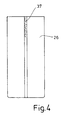
- the device according to the invention By means of the device according to the invention it has now become possible to print all around the can body in high print quality by means of the thermal transfer printing process. At the same time, the quality of the transfer printing of the overlap area has been made so high that this transfer printing section no longer has a disruptive influence on the overall appearance of a printed can, which is due to the fact that the color particles in the area of the overlap forming a printing strip 37 by appropriate pressing , Heating and any other process described have the same or lower color intensity than the color particles outside the overlap.
Landscapes
- Physics & Mathematics (AREA)
- Optics & Photonics (AREA)
- Printing Methods (AREA)
- Treatments Of Macromolecular Shaped Articles (AREA)
- Application Of Or Painting With Fluid Materials (AREA)
- Thermal Transfer Or Thermal Recording In General (AREA)
- Coating With Molten Metal (AREA)
- Screen Printers (AREA)
- Decoration By Transfer Pictures (AREA)
- Superconductors And Manufacturing Methods Therefor (AREA)
- Chemically Coating (AREA)
Applications Claiming Priority (2)
| Application Number | Priority Date | Filing Date | Title |
|---|---|---|---|
| CH3867/89A CH679218A5 (fr) | 1989-10-26 | 1989-10-26 | |
| CH3867/89 | 1989-10-26 |
Publications (3)
| Publication Number | Publication Date |
|---|---|
| EP0424812A2 true EP0424812A2 (fr) | 1991-05-02 |
| EP0424812A3 EP0424812A3 (en) | 1992-04-08 |
| EP0424812B1 EP0424812B1 (fr) | 1994-07-20 |
Family
ID=4265194
Family Applications (1)
| Application Number | Title | Priority Date | Filing Date |
|---|---|---|---|
| EP90120030A Expired - Lifetime EP0424812B1 (fr) | 1989-10-26 | 1990-10-19 | Procédé pour le traitement de la surface d'un corps creux métallique |
Country Status (15)
| Country | Link |
|---|---|
| US (1) | US5156711A (fr) |
| EP (1) | EP0424812B1 (fr) |
| JP (1) | JPH03173644A (fr) |
| KR (1) | KR910007695A (fr) |
| CN (1) | CN1051141A (fr) |
| AT (1) | ATE108729T1 (fr) |
| AU (1) | AU652128B2 (fr) |
| BG (1) | BG60048B2 (fr) |
| BR (1) | BR9005548A (fr) |
| CA (1) | CA2027976A1 (fr) |
| CH (1) | CH679218A5 (fr) |
| DE (1) | DE59006497D1 (fr) |
| MX (1) | MX173113B (fr) |
| RU (1) | RU2041830C1 (fr) |
| ZA (1) | ZA907889B (fr) |
Cited By (2)
| Publication number | Priority date | Publication date | Assignee | Title |
|---|---|---|---|---|
| WO2007110752A3 (fr) * | 2006-03-27 | 2008-02-14 | Viv Int Spa | Appareil pour decorer des objets |
| CN103112247A (zh) * | 2012-12-10 | 2013-05-22 | 苏州一致电子制程有限公司 | 热转印机箱体 |
Families Citing this family (19)
| Publication number | Priority date | Publication date | Assignee | Title |
|---|---|---|---|---|
| DE4427870A1 (de) * | 1994-08-06 | 1996-02-08 | Alfill Getraenketechnik | Verfahren und Vorrichtung zum Bedrucken von gewölbten bzw. rotationssymmetrischen Oberflächen von kontinuierlich geförderten Behältern der Getränkeindustrie |
| FR2748232B1 (fr) * | 1996-05-03 | 1998-07-17 | Dubuit Mach | Machine a imprimer a plateau tournant |
| US6054006A (en) * | 1997-12-01 | 2000-04-25 | Great Pacific Enterprises, Inc., Through Its Division, Montebello Packaging | Method and apparatus for applying a printed label to a metal container and the labeled container produced thereby |
| US6423169B1 (en) * | 2000-03-09 | 2002-07-23 | Hunter Manufacturing Group, Inc. | Sublimation heat transfer system and related method |
| CN100343078C (zh) * | 2003-07-03 | 2007-10-17 | 盛鑫实业股份有限公司 | 自动立式罐胴定点图形或文字成型方法 |
| RU2255001C1 (ru) * | 2003-10-20 | 2005-06-27 | Базылев Владимир Аркадьевич | Способ нанесения рисунка на окрашенную поверхность металлических изделий и устройство для его осуществления |
| DE502005002250D1 (de) * | 2005-11-03 | 2008-01-24 | Ball Packaging Europ Holding G | Spanndorn für den Digitaldruck |
| DE102008056797A1 (de) * | 2008-11-11 | 2010-05-12 | Kmk Lizence Ltd. | Vorrichtung sowie Verfahren zum Herstellen von Tuben |
| CN102079164B (zh) * | 2010-10-27 | 2012-05-02 | 东莞市创智涂装设备工程有限公司 | 级进式自动移印机 |
| CN102275397B (zh) * | 2011-06-27 | 2013-05-01 | 浙江华人数码印刷有限公司 | 金属板材上的热转印工艺 |
| CN102514775B (zh) * | 2011-11-10 | 2014-10-15 | 深圳市通产丽星股份有限公司 | 一种用于包装软管生产的设备及其使用方法 |
| CN102380224B (zh) * | 2011-11-25 | 2013-12-18 | 苏州华微特粉体技术有限公司 | 一种升华器 |
| CN102991103B (zh) * | 2012-11-29 | 2015-11-18 | 苏州一致电子制程有限公司 | 多工位加工治具 |
| JP6255212B2 (ja) * | 2013-10-25 | 2017-12-27 | 昭和アルミニウム缶株式会社 | 缶体の製造方法、印刷装置、および、飲料用缶 |
| CN103935117B (zh) * | 2014-03-13 | 2016-01-06 | 宁波铭匠扎啤设备有限公司 | 一种对扎啤酒桶印字的设备和工艺 |
| CN107244154A (zh) * | 2017-06-22 | 2017-10-13 | 上海丹运实业有限公司 | 一种金属冷凝罐热转印方法 |
| US11897277B2 (en) * | 2021-02-19 | 2024-02-13 | Cricut, Inc. | Sublimation systems and related methods |
| US11407245B1 (en) | 2021-02-17 | 2022-08-09 | Cricut, Inc. | Sublimation systems and related methods |
| EP4380800A4 (fr) * | 2021-08-05 | 2025-06-18 | Sekisui Kydex, LLC | Appareil de sublimation de colorant multi-station pour préchauffer et faciliter des cycles de sublimation simultanés |
Family Cites Families (7)
| Publication number | Priority date | Publication date | Assignee | Title |
|---|---|---|---|---|
| US3718517A (en) * | 1970-02-19 | 1973-02-27 | T Berg | Method and apparatus for decorating articles |
| US4175993A (en) * | 1977-11-09 | 1979-11-27 | Ethyl Development Corporation | Article decorating machine and method |
| US4250831A (en) * | 1978-09-18 | 1981-02-17 | Coors Container Company | Apparatus for printing cans from heat transfer paper |
| US4397710A (en) * | 1982-01-22 | 1983-08-09 | The Meyercord Co. | Machine for applying indicia to tapered or straight cylindrical articles |
| US4444613A (en) * | 1982-05-17 | 1984-04-24 | Owens-Illinois, Inc. | Apparatus for producing tubular plastic sleeves for application to containers |
| US4604154A (en) * | 1983-11-28 | 1986-08-05 | Owens-Illinois, Inc. | Apparatus and method for guiding plastic labels to a label-wrapping station |
| AU2523188A (en) * | 1987-10-02 | 1989-04-18 | Toyo Seikan Kaisha Ltd. | Multi-color printing method for container |
-
1989
- 1989-10-26 CH CH3867/89A patent/CH679218A5/de not_active IP Right Cessation
-
1990
- 1990-10-03 ZA ZA907889A patent/ZA907889B/xx unknown
- 1990-10-04 AU AU63768/90A patent/AU652128B2/en not_active Ceased
- 1990-10-16 BG BG093020A patent/BG60048B2/bg unknown
- 1990-10-17 US US07/598,981 patent/US5156711A/en not_active Expired - Fee Related
- 1990-10-18 CA CA002027976A patent/CA2027976A1/fr not_active Abandoned
- 1990-10-19 EP EP90120030A patent/EP0424812B1/fr not_active Expired - Lifetime
- 1990-10-19 DE DE59006497T patent/DE59006497D1/de not_active Expired - Fee Related
- 1990-10-19 AT AT90120030T patent/ATE108729T1/de not_active IP Right Cessation
- 1990-10-23 KR KR1019900016978A patent/KR910007695A/ko not_active Withdrawn
- 1990-10-23 JP JP2285691A patent/JPH03173644A/ja active Pending
- 1990-10-23 MX MX022964A patent/MX173113B/es unknown
- 1990-10-24 CN CN90108713A patent/CN1051141A/zh active Pending
- 1990-10-25 RU SU904831385A patent/RU2041830C1/ru active
- 1990-10-26 BR BR909005548A patent/BR9005548A/pt active Search and Examination
Cited By (3)
| Publication number | Priority date | Publication date | Assignee | Title |
|---|---|---|---|---|
| WO2007110752A3 (fr) * | 2006-03-27 | 2008-02-14 | Viv Int Spa | Appareil pour decorer des objets |
| US8276634B2 (en) | 2006-03-27 | 2012-10-02 | Decoral System Usa Corp. | Apparatus for decorating objects |
| CN103112247A (zh) * | 2012-12-10 | 2013-05-22 | 苏州一致电子制程有限公司 | 热转印机箱体 |
Also Published As
| Publication number | Publication date |
|---|---|
| US5156711A (en) | 1992-10-20 |
| ATE108729T1 (de) | 1994-08-15 |
| DE59006497D1 (de) | 1994-08-25 |
| AU652128B2 (en) | 1994-08-18 |
| MX173113B (es) | 1994-02-01 |
| AU6376890A (en) | 1991-05-02 |
| CA2027976A1 (fr) | 1991-04-27 |
| RU2041830C1 (ru) | 1995-08-20 |
| JPH03173644A (ja) | 1991-07-26 |
| BR9005548A (pt) | 1991-09-17 |
| CH679218A5 (fr) | 1992-01-15 |
| BG60048B2 (bg) | 1993-08-30 |
| EP0424812B1 (fr) | 1994-07-20 |
| EP0424812A3 (en) | 1992-04-08 |
| ZA907889B (en) | 1991-07-31 |
| CN1051141A (zh) | 1991-05-08 |
| KR910007695A (ko) | 1991-05-30 |
Similar Documents
| Publication | Publication Date | Title |
|---|---|---|
| EP0424812B1 (fr) | Procédé pour le traitement de la surface d'un corps creux métallique | |
| EP0089494B1 (fr) | Procédé et dispositif pour gaufrer une bande flexible continue | |
| EP0033776B1 (fr) | Procédé et dispositif de mise en couleur ou d'impression d'objets en forme de bande, en particulier de garnitures de ski, et objets d'une telle nature | |
| DE2908341A1 (de) | Wickelkern, verfahren zu seiner herstellung, verfahren zum wickeln einer materialbahn unter verwendung des wickelkerns und dafuer geeignete vorrichtung | |
| DE19733339A1 (de) | Vorrichtung und Verfahren zum Aufbringen von klebefähigem Blattmaterial | |
| EP0573676A1 (fr) | Utilisation d'une bande de support ayant des propriétés de décollage pour l'application de laque et de teinture sur un substrat | |
| DE2708354A1 (de) | Verfahren zum verzieren eines zylindrischen koerpers und vorrichtung zur durchfuehrung des verfahrens | |
| DE102012109315A1 (de) | Verfahren und Vorrichtung zum Beprägen einer nicht-ebenen Oberfläche eines Körpers mit einer Übertragungslage einer Heißprägefolie | |
| DE3935602C2 (fr) | ||
| DE4240938C2 (de) | Vorrichtung zum Einfärben und Prägen von Schildern, insbesondere von Kraftfahrzeug-Kennzeichenschildern | |
| EP0195857A2 (fr) | Procédé et appareil pour le transfert d'images sur feuille vers un support à imprimer | |
| EP0584542B1 (fr) | Méthode et dispositif pour imprimer des objets | |
| DE4309400C2 (de) | Heißprägevorrichtung zum Einfärben von Unterlagen, insbesondere von Schildern | |
| DE3935604C2 (fr) | ||
| DE2248181A1 (de) | Verfahren und vorrichtung zum verkleben flaechenfoermiger textilstuecke | |
| DE3229815C2 (fr) | ||
| DE4432018A1 (de) | Vorrichtung und Verfahren zum Übertragen eines Dekors auf konvex gekrümmte Oberflächen | |
| CH679294A5 (en) | Transfer-printing method - passes conductive loop along support wrapped round hollow metal body on mandrel | |
| CH679217A5 (en) | Transfer-wrapping mechanism round metal body - supports body on mandrel round which wrapping blades travel | |
| EP4028261A1 (fr) | Procédé et dispositif de finition d'épreuves | |
| DE3935605C2 (fr) | ||
| CH679026A5 (en) | Cylindrical body painted by heat-transfer - uses auxiliary support with reduced-intensity paint at overlapping portion | |
| DE3935603A1 (de) | Mittels thermotransferdruck dekorierter dosenkoerper | |
| DE1126127B (de) | Vorrichtung zum Waermebehandeln thermoplastischer Kunststoffbahnen | |
| DE2437708B2 (de) | Vorrichtung zum Färben oder Bedrucken von Warenbahnen |
Legal Events
| Date | Code | Title | Description |
|---|---|---|---|
| PUAI | Public reference made under article 153(3) epc to a published international application that has entered the european phase |
Free format text: ORIGINAL CODE: 0009012 |
|
| AK | Designated contracting states |
Kind code of ref document: A2 Designated state(s): AT BE CH DE DK ES FR GB GR IT LI LU NL SE |
|
| PUAL | Search report despatched |
Free format text: ORIGINAL CODE: 0009013 |
|
| AK | Designated contracting states |
Kind code of ref document: A3 Designated state(s): AT BE CH DE DK ES FR GB GR IT LI LU NL SE |
|
| 17P | Request for examination filed |
Effective date: 19920814 |
|
| 17Q | First examination report despatched |
Effective date: 19930120 |
|
| GRAA | (expected) grant |
Free format text: ORIGINAL CODE: 0009210 |
|
| AK | Designated contracting states |
Kind code of ref document: B1 Designated state(s): AT BE CH DE DK ES FR GB GR IT LI LU NL SE |
|
| PG25 | Lapsed in a contracting state [announced via postgrant information from national office to epo] |
Ref country code: NL Effective date: 19940720 Ref country code: GR Free format text: LAPSE BECAUSE OF FAILURE TO SUBMIT A TRANSLATION OF THE DESCRIPTION OR TO PAY THE FEE WITHIN THE PRESCRIBED TIME-LIMIT Effective date: 19940720 Ref country code: ES Free format text: THE PATENT HAS BEEN ANNULLED BY A DECISION OF A NATIONAL AUTHORITY Effective date: 19940720 Ref country code: DK Effective date: 19940720 Ref country code: BE Effective date: 19940720 |
|
| REF | Corresponds to: |
Ref document number: 108729 Country of ref document: AT Date of ref document: 19940815 Kind code of ref document: T |
|
| REF | Corresponds to: |
Ref document number: 59006497 Country of ref document: DE Date of ref document: 19940825 |
|
| ITF | It: translation for a ep patent filed | ||
| PG25 | Lapsed in a contracting state [announced via postgrant information from national office to epo] |
Ref country code: AT Effective date: 19941019 |
|
| PG25 | Lapsed in a contracting state [announced via postgrant information from national office to epo] |
Ref country code: SE Effective date: 19941020 |
|
| PGFP | Annual fee paid to national office [announced via postgrant information from national office to epo] |
Ref country code: FR Payment date: 19941026 Year of fee payment: 5 |
|
| PG25 | Lapsed in a contracting state [announced via postgrant information from national office to epo] |
Ref country code: LU Free format text: LAPSE BECAUSE OF NON-PAYMENT OF DUE FEES Effective date: 19941031 |
|
| PGFP | Annual fee paid to national office [announced via postgrant information from national office to epo] |
Ref country code: GB Payment date: 19941117 Year of fee payment: 5 |
|
| ET | Fr: translation filed | ||
| GBT | Gb: translation of ep patent filed (gb section 77(6)(a)/1977) |
Effective date: 19941104 |
|
| NLV1 | Nl: lapsed or annulled due to failure to fulfill the requirements of art. 29p and 29m of the patents act | ||
| PGFP | Annual fee paid to national office [announced via postgrant information from national office to epo] |
Ref country code: DE Payment date: 19950201 Year of fee payment: 5 |
|
| PLBE | No opposition filed within time limit |
Free format text: ORIGINAL CODE: 0009261 |
|
| STAA | Information on the status of an ep patent application or granted ep patent |
Free format text: STATUS: NO OPPOSITION FILED WITHIN TIME LIMIT |
|
| 26N | No opposition filed | ||
| PG25 | Lapsed in a contracting state [announced via postgrant information from national office to epo] |
Ref country code: GB Effective date: 19951019 |
|
| GBPC | Gb: european patent ceased through non-payment of renewal fee |
Effective date: 19951019 |
|
| PG25 | Lapsed in a contracting state [announced via postgrant information from national office to epo] |
Ref country code: FR Effective date: 19960628 |
|
| PG25 | Lapsed in a contracting state [announced via postgrant information from national office to epo] |
Ref country code: DE Effective date: 19960702 |
|
| REG | Reference to a national code |
Ref country code: FR Ref legal event code: ST |
|
| PGFP | Annual fee paid to national office [announced via postgrant information from national office to epo] |
Ref country code: CH Payment date: 19990929 Year of fee payment: 10 |
|
| REG | Reference to a national code |
Ref country code: CH Ref legal event code: PFA Free format text: DECOREX LIZENZ AG,ROTZBERGSTRASSE 7,6362 STANSSTAD (CH) TRANSFER- DECOREX LIZENZ AG,BERGSTRASSE 39,6004 LUZERN (CH) |
|
| PG25 | Lapsed in a contracting state [announced via postgrant information from national office to epo] |
Ref country code: LI Free format text: LAPSE BECAUSE OF THE APPLICANT RENOUNCES Effective date: 20001031 Ref country code: CH Free format text: LAPSE BECAUSE OF THE APPLICANT RENOUNCES Effective date: 20001031 |
|
| REG | Reference to a national code |
Ref country code: CH Ref legal event code: PL |
|
| PG25 | Lapsed in a contracting state [announced via postgrant information from national office to epo] |
Ref country code: IT Free format text: LAPSE BECAUSE OF NON-PAYMENT OF DUE FEES;WARNING: LAPSES OF ITALIAN PATENTS WITH EFFECTIVE DATE BEFORE 2007 MAY HAVE OCCURRED AT ANY TIME BEFORE 2007. THE CORRECT EFFECTIVE DATE MAY BE DIFFERENT FROM THE ONE RECORDED. Effective date: 20051019 |