EP0424817A1 - Elément enfichable ou dispositif essentiellement cubique - Google Patents
Elément enfichable ou dispositif essentiellement cubique Download PDFInfo
- Publication number
- EP0424817A1 EP0424817A1 EP90120065A EP90120065A EP0424817A1 EP 0424817 A1 EP0424817 A1 EP 0424817A1 EP 90120065 A EP90120065 A EP 90120065A EP 90120065 A EP90120065 A EP 90120065A EP 0424817 A1 EP0424817 A1 EP 0424817A1
- Authority
- EP
- European Patent Office
- Prior art keywords
- devices
- electrical
- plug
- arrangement
- cable
- Prior art date
- Legal status (The legal status is an assumption and is not a legal conclusion. Google has not performed a legal analysis and makes no representation as to the accuracy of the status listed.)
- Granted
Links
Images
Classifications
-
- H—ELECTRICITY
- H01—ELECTRIC ELEMENTS
- H01H—ELECTRIC SWITCHES; RELAYS; SELECTORS; EMERGENCY PROTECTIVE DEVICES
- H01H50/00—Details of electromagnetic relays
- H01H50/14—Terminal arrangements
-
- H—ELECTRICITY
- H01—ELECTRIC ELEMENTS
- H01H—ELECTRIC SWITCHES; RELAYS; SELECTORS; EMERGENCY PROTECTIVE DEVICES
- H01H50/00—Details of electromagnetic relays
- H01H50/02—Bases; Casings; Covers
- H01H50/021—Bases; Casings; Covers structurally combining a relay and an electronic component, e.g. varistor, RC circuit
Definitions
- the present invention relates to an essentially cubic plug component or device with electrical plug sockets arranged in a circle or likewise arranged plug pins, which are suitable for the transmission of mains voltage energy.
- Such cubic devices be they bases, for example for plugging on industrial relays, or plug-on devices, such as the aforementioned industrial relays, are known and are often used in industrial controls, switchgear, etc., together with other electrical units, often a large number of such , used as a base of trained devices, arranged in rows.
- the present invention therefore basically sets itself the task, starting from the above-mentioned known devices, to create devices which make it possible to make optimal use of the available installation areas.
- the device according to the invention is distinguished by the wording of the characterizing part of claim 1.
- the present invention is based on the realization that the volume spanned by the base component is in no way used for electro-technical purposes and is also not necessary from a mechanical stability point of view in the case of such devices designed as plug-in bases.
- This measure can be provided individually on conventional devices or is provided individually or together for the consequent further development of the device specified in claim 1 or 2, in combination with the measures specified there.
- the device is designed according to the wording of claim 3, results in a highly flexible wiring option, for example, by driving the drive energy for a component to be plugged onto the base device over the pair of electrical contacts, which are connected in operation by a bridging plug or resiliently against each other and separated, for example, during service or inspection work in which the corresponding base device with the device arranged thereon is to be put out of operation for a short time.
- the present invention is based on the realization that the object of the invention is based on the knowledge that only as many, usually screwable, cable connections are provided in the case of devices of the abovementioned type which are conventionally designed as bases, as are provided on the circular socket arrangement.
- the electrical connection between the cable connections and the mentioned sockets is usually hard-wired in the base.
- the present invention again assumes that the space occupied by the conventional base devices is not used for the intended purpose.
- This measure can also be used on known devices of the type mentioned above or can be combined with at least one of the measures just explained.
- This measure can in principle be used in electrical devices and is used in a particularly advantageous manner on the devices of the type mentioned at the outset, be it as an individual measure or be combined with one or more of the measures specified in claims 1 to 4.
- the devices are now proposed according to claim 1 with width adapters according to the wording of claim 8, preferably, for optimal use of space according to claim 10, to combine them in a kit so that, flexibly, devices according to claim 1 can be used in existing installations and / or devices according to claim 1 with conventional devices Dimensioning can be combined as desired.
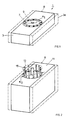
- FIGS. 1 and 2 show, schematically, electrical devices according to the present invention.
- Figure 1 shows a base, for example for industrial relays. Only the elements necessary to describe the first measure according to the invention are shown.
- the structure of the plug-in base 1 is otherwise the same as the widespread "industrial relay" base, which is frequently used, for example, in control cabinets.
- Known plug-in bases of this type as shown in dashed lines, comprise a substantially cuboid housing body 3a, made of plastic, preferably as a molded component, on one side in a circle order 5, sockets 7 for electrical contacting of plugged-on electrical devices with correspondingly arranged electrical contact pins are provided.
- the socket circuit arrangement 5 is also known in its design and is therefore only shown schematically. It has a positioning and holding opening 9 in its center, for attached devices.
- Circular plug-in arrangements of this type are known, 8-pin under the standard IEC 67-1-5a, c, d, 11-pin under IEC 67-1-18a.
- the previously customary plug-in bases 3a are considerably wider than would be necessary for a given diameter ⁇ 5 of the socket circuit arrangement 5.
- conventional base devices are 38 mm wide, with an outside diameter of the said circular arrangement of less than 25 mm. If two or a plurality of such base devices 1 are mounted laterally next to one another, this results in a packing density in which practically a third of the width is unused.
- the width dimension B of the base device according to the invention or its cuboid housing 3 is only defined by the outside diameter ⁇ 5 of the circular arrangement 5, if necessary taking into account the necessary leakage current and air gaps between Sockets or pins of neighboring device arrangements.
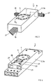
- FIG. 2 in the same representation as in Fig. 1, another device, now designed as a plug-in, shown, in known form (dashed) and according to the invention (extended).
- the device according to the invention in turn comprises a cuboid housing 11, preferably made of plastic, with the width dimension B corresponding to the diameter ⁇ 13 of the circular plug 13 provided here with pins 15.
- a device can, for example, a power relay-An in its housing 11 order included.
- FIG. 3 A further measure according to the invention on a device of the type shown in FIG. 1 will now be explained with reference to FIG. 3, this measure, in itself, already providing a significantly improved cabling option than conventional pedestal devices, but this in particular in combination with the 1 shows a design variant in which the installation effort is significantly reduced both by a new high packing density and by a new clever possibility of cabling.
- FIG. 3 again shows a plug-in base device 1 with a plastic housing 3 or 3a. Since a substantial part of the housing volume of such base devices 1 lies idle with regard to usable space, i.e. valuable installation space is blocked by the voluminous housing, according to the invention, preferably centrally and on the side of the housing 3 facing away from the circular socket arrangement 5, a longitudinally continuous channel or Shaft 19 provided. As shown schematically, through this channel 19 cables 21 can be routed from one side of the plug base 1 to the other side without the lateral joining of the plug bases 1 being impeded or unnecessary space being wasted due to the wiring that is necessary anyway. This means that no additional cable routing is required.
- the two measures described individually with reference to FIGS. 1 and 3 can preferably be combined to enable such devices to be installed in a space-optimized manner.
- the socket device 1 in turn has a circular arrangement 5 of sockets 7, conventionally their eleven or eight according to the standards specified above. Furthermore, the cuboid plastic housing 3, 3a is provided with cable connections 25. As can be easily seen, in the eleven sockets 7 provided here, twelve cable connections 25 are provided for the cabling of the plug-in base 1; in the case of eight sockets 7, there would be nine cable connections.
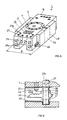
- the second measure to be explained with reference to FIG. 4 is that, preferably on the same cuboid area on which the circular plug 5 is arranged, a holding recess 29 with electrical contacts 31 accessible therein is provided.
- a holding recess 29 with electrical contacts 31 accessible therein is provided.
- two pairs of opposing, resilient contact tabs 31 are provided. These contact tabs 31 are preferably electrically connected inside the base to the desired number of cable connections 25 provided.
- additional modules can be arranged, which are contacted by the tabs 31, such as Interference suppression circuits, logic circuits, timing elements etc.
- the holding recess can itself lie within the area covered by a device plugged onto the base device 1 and / or next to it. If necessary, it is formed so deep that it can accommodate an additional module without the latter obstructing the device plugged onto the connector 5.
- FIG. 5 shows a further embodiment variant of the base device 1, in which the measures which have been explained individually with reference to FIGS. 1, 3 and 4 are provided in combination:
- FIG. 5 shows a preferred embodiment of the invention.
- two further measures are provided for it, which are also only individually as part of a solution to the Invention based task can be used on a base device 1.
- the width dimension described with reference to FIG. 1 further has, in the case of the eleven sockets 7 shown here, twelve cable connections 25 and also the recess 29 with tabs 31 described with reference to FIG. 4.
- the measures additionally provided here are a) a particularly space-saving arrangement of the cable connections 25 and b) the provision of adapter parts 35.
- the side surfaces at which the connections 25 open out are essentially planar, and all connections 25 open out in the same plane.
- the lateral connections 25 are also aligned with one another in the direction of the axes of the locking screws 27.
- connection 25 which in contrast to the known embodiment according to FIG. 4 now open on a flat cube disc, can be operated by the locking screws and, in addition, the requirements for the assembly of the cables, as far as their stripping is concerned, remain the same for all connections 25 , is shown as schematically At least one of the connections 25 and 25a lying one above the other sets the locking screw 27a to the rear and engages from behind with a protruding contacting part in the connection 25a.
- FIG. 6 shows an embodiment variant of the protruding contact shown schematically in FIG. 5.
- the screw 27a has an upper cylindrical, smooth section 37 which is in an equally smooth bore in the housing 1.
- the screw 27a protrudes through the cable connection 25a and is secured on its upper edge surface by means of a collar 38 against axial movements.
- the part 39 of the locking screw 27a projecting through the cable connection 25a has a thread 40, on which, provided with a corresponding threaded bush 41, a contact arm 42 rides, which is moved up and down by rotating the screw 27a, as shown at P. 6, a "normal" locking screw 27 is shown in dashed lines, positioned with respect to the cable connection 27a in the same way as, according to FIG. 5, the screw 27 with respect to the connection 25.
- connection socket 25a is also preferably designed here by means of a pluggable metal socket 43.
- a stop surface 44 preferably formed on the arm 42 as part of the threaded bush 41, ensures that a properly inserted cable end, possibly with strands, does not impair the function of the locking screw 27a or that the screw thread does not damage the cable end.
- the adapter parts 35 are provided, preferably dimensioned according to half the width difference of the conventional and the inventive base devices.
- the adapter parts are preferably made of plastic, can be plugged onto conventional holding rails (not shown) for the base devices 1 or, for example, can be attached to corresponding side surfaces of the base devices 1 according to the invention. This achieves the greatest possible versatility for plug-in base devices dimensioned according to the invention. Cable guides can again be provided in these adapter parts, as shown in dashed lines at 46, and / or these adapter parts 35 can be provided for accommodating further devices 48, such as for filters, timing elements, etc.
Landscapes
- Physics & Mathematics (AREA)
- Electromagnetism (AREA)
- Connector Housings Or Holding Contact Members (AREA)
- Details Of Connecting Devices For Male And Female Coupling (AREA)
- Details Of Indoor Wiring (AREA)
- Mechanical Coupling Of Light Guides (AREA)
- Control Of Motors That Do Not Use Commutators (AREA)
- Ceramic Products (AREA)
- Cartons (AREA)
Applications Claiming Priority (2)
| Application Number | Priority Date | Filing Date | Title |
|---|---|---|---|
| DE3935456 | 1989-10-25 | ||
| DE3935456A DE3935456A1 (de) | 1989-10-25 | 1989-10-25 | Im wesentlichen kubischer steckerbauteil bzw. geraet |
Publications (2)
| Publication Number | Publication Date |
|---|---|
| EP0424817A1 true EP0424817A1 (fr) | 1991-05-02 |
| EP0424817B1 EP0424817B1 (fr) | 1996-05-22 |
Family
ID=6392131
Family Applications (1)
| Application Number | Title | Priority Date | Filing Date |
|---|---|---|---|
| EP90120065A Expired - Lifetime EP0424817B1 (fr) | 1989-10-25 | 1990-10-19 | Elément enfichable ou dispositif essentiellement cubique |
Country Status (5)
| Country | Link |
|---|---|
| EP (1) | EP0424817B1 (fr) |
| AT (1) | ATE138494T1 (fr) |
| DE (2) | DE3935456A1 (fr) |
| DK (1) | DK0424817T3 (fr) |
| ES (1) | ES2088937T3 (fr) |
Cited By (1)
| Publication number | Priority date | Publication date | Assignee | Title |
|---|---|---|---|---|
| WO2007137535A1 (fr) * | 2006-05-26 | 2007-12-06 | Siemens Aktiengesellschaft | Dispositif de contrôle d'une armoire électrique dotée d'un bornier d'entrée |
Families Citing this family (2)
| Publication number | Priority date | Publication date | Assignee | Title |
|---|---|---|---|---|
| DE10002625B4 (de) * | 2000-01-22 | 2010-03-11 | E.G.O. Elektro-Gerätebau GmbH | Verfahren zur Herstellung eines Schaltgerätesockels |
| CN101246792B (zh) * | 2007-06-12 | 2010-05-19 | 上海继电器有限公司 | 埋入式继电器板前接线座 |
Citations (2)
| Publication number | Priority date | Publication date | Assignee | Title |
|---|---|---|---|---|
| DE1907481U (de) * | 1964-05-22 | 1964-12-31 | Helmut Schleicher | Zeitrelais. |
| DE3221042A1 (de) * | 1982-06-04 | 1983-12-08 | Karl Lumberg GmbH & Co, 5885 Schalksmühle | Relaisfassung |
Family Cites Families (7)
| Publication number | Priority date | Publication date | Assignee | Title |
|---|---|---|---|---|
| CH362135A (de) * | 1958-09-25 | 1962-05-31 | Mawex Ag | Elektrische Verbindungsklemme |
| FR1544000A (fr) * | 1967-07-12 | 1968-10-31 | Dispositif de connexion pour conducteurs électriques | |
| JPS4892873A (fr) * | 1972-03-10 | 1973-12-01 | ||
| CH621649A5 (en) * | 1978-01-20 | 1981-02-13 | Elesta Ag Elektronik | Base for a device provided with plug-in contacts, in particular for a relay |
| DE3233255C2 (de) * | 1982-09-08 | 1984-09-27 | Phönix Elektrizitätsgesellschaft H. Knümann GmbH & Co KG, 4933 Blomberg | Elektrische Anschlußklemme, insbesondere Schaltanlagen-Reihenklemme |
| DE3710684A1 (de) * | 1987-03-31 | 1988-10-20 | Murr Formenbau Gmbh | Winkelstecker |
| DE3801675C2 (de) * | 1988-01-21 | 1997-01-30 | Festo Kg | Steckvorrichtung zum Anschluß elektrischer Geräte, insbesondere in Reihen angeordneter Magnetventile |
-
1989
- 1989-10-25 DE DE3935456A patent/DE3935456A1/de active Granted
-
1990
- 1990-10-19 ES ES90120065T patent/ES2088937T3/es not_active Expired - Lifetime
- 1990-10-19 EP EP90120065A patent/EP0424817B1/fr not_active Expired - Lifetime
- 1990-10-19 DK DK90120065.9T patent/DK0424817T3/da active
- 1990-10-19 DE DE59010336T patent/DE59010336D1/de not_active Expired - Fee Related
- 1990-10-19 AT AT90120065T patent/ATE138494T1/de active
Patent Citations (2)
| Publication number | Priority date | Publication date | Assignee | Title |
|---|---|---|---|---|
| DE1907481U (de) * | 1964-05-22 | 1964-12-31 | Helmut Schleicher | Zeitrelais. |
| DE3221042A1 (de) * | 1982-06-04 | 1983-12-08 | Karl Lumberg GmbH & Co, 5885 Schalksmühle | Relaisfassung |
Cited By (2)
| Publication number | Priority date | Publication date | Assignee | Title |
|---|---|---|---|---|
| WO2007137535A1 (fr) * | 2006-05-26 | 2007-12-06 | Siemens Aktiengesellschaft | Dispositif de contrôle d'une armoire électrique dotée d'un bornier d'entrée |
| CN101449172B (zh) * | 2006-05-26 | 2012-07-04 | 西门子公司 | 用于带有输入端子模块的开关柜的检验装置 |
Also Published As
| Publication number | Publication date |
|---|---|
| ATE138494T1 (de) | 1996-06-15 |
| ES2088937T3 (es) | 1996-10-01 |
| DE59010336D1 (de) | 1996-06-27 |
| DK0424817T3 (da) | 1996-08-26 |
| EP0424817B1 (fr) | 1996-05-22 |
| DE3935456C2 (fr) | 1991-11-14 |
| DE3935456A1 (de) | 1991-05-16 |
Similar Documents
| Publication | Publication Date | Title |
|---|---|---|
| DE4121836C2 (de) | Reihenklemme mit Aufsteckmodul | |
| DE19964156B4 (de) | Elektrisches Gerät | |
| DE4438805C1 (de) | Feldbusanschlußmodul | |
| DE69008139T2 (de) | Bauelementensatz zum gleizeitigen elektrischen Verbinden einer Mehrzahl von modularen Selbstschaltern. | |
| DE29607525U1 (de) | Modulares, baugruppenweise erweiterbares Peripheriegerät mit selbstaufbauender elektrischer Verbindung | |
| DE2906030A1 (de) | Anschlussbaustein, insbesondere fuer die verbindung zwischen fernsprech-amtsleitungen und teilnehmerleitungen | |
| EP0436804A2 (fr) | Unité d'installation électrique pour installations domestiques | |
| DE102007019805B4 (de) | Kabelkasten | |
| EP3631922A1 (fr) | Tableau de distribution électrique | |
| EP0180856A2 (fr) | Appareil électrique | |
| DE69110382T2 (de) | Elektrischer Verbinder. | |
| DE2708291A1 (de) | Elektrische steckvorrichtung | |
| DE3943752C2 (de) | Pneumatische oder hydraulische Ventileinheit | |
| EP0424817B1 (fr) | Elément enfichable ou dispositif essentiellement cubique | |
| WO2022106262A1 (fr) | Borne pour lignes électriques | |
| DE3227819C2 (de) | Steckverbinder mit einlegbarer Sicherung | |
| DE2417285C2 (de) | Gestell zur Aufnahme von elektrischen oder elektronischen Schaltungen | |
| EP0702502A1 (fr) | Interface de programmation pour prothèses auditives | |
| DE19610037C2 (de) | Baugruppenträger | |
| DE9003879U1 (de) | Kabelstecker-Verteiler-Kasten | |
| DE3340975C2 (de) | Vorrichtung zur lösbaren Montage mehrerer Schaltungsplatten auf einer Trägerplatte | |
| DE3412244C2 (de) | Fernmelde-Anschlußdose | |
| DE3214484C2 (de) | Vorrichtung zur optischen Anzeige des Betriebszustandes eines wegen einer Isolation oder Kapselung unzulänglichen Leiters eines Energieversorgungsnetzes | |
| EP0871130B1 (fr) | Unité de couplage électrique avec interface de bus | |
| DE10117758A1 (de) | Baugruppe für ein Automatisierungsgerät |
Legal Events
| Date | Code | Title | Description |
|---|---|---|---|
| PUAI | Public reference made under article 153(3) epc to a published international application that has entered the european phase |
Free format text: ORIGINAL CODE: 0009012 |
|
| AK | Designated contracting states |
Kind code of ref document: A1 Designated state(s): AT BE CH DE DK ES FR GB IT LI LU NL SE |
|
| 17P | Request for examination filed |
Effective date: 19910328 |
|
| 17Q | First examination report despatched |
Effective date: 19931215 |
|
| GRAH | Despatch of communication of intention to grant a patent |
Free format text: ORIGINAL CODE: EPIDOS IGRA |
|
| GRAA | (expected) grant |
Free format text: ORIGINAL CODE: 0009210 |
|
| AK | Designated contracting states |
Kind code of ref document: B1 Designated state(s): AT BE CH DE DK ES FR GB IT LI LU NL SE |
|
| REF | Corresponds to: |
Ref document number: 138494 Country of ref document: AT Date of ref document: 19960615 Kind code of ref document: T |
|
| REG | Reference to a national code |
Ref country code: CH Ref legal event code: NV Representative=s name: TROESCH SCHEIDEGGER WERNER AG |
|
| REF | Corresponds to: |
Ref document number: 59010336 Country of ref document: DE Date of ref document: 19960627 |
|
| ET | Fr: translation filed | ||
| REG | Reference to a national code |
Ref country code: ES Ref legal event code: BA2A Ref document number: 2088937 Country of ref document: ES Kind code of ref document: T3 |
|
| GBT | Gb: translation of ep patent filed (gb section 77(6)(a)/1977) |
Effective date: 19960619 |
|
| ITF | It: translation for a ep patent filed | ||
| REG | Reference to a national code |
Ref country code: DK Ref legal event code: T3 |
|
| REG | Reference to a national code |
Ref country code: ES Ref legal event code: FG2A Ref document number: 2088937 Country of ref document: ES Kind code of ref document: T3 |
|
| PG25 | Lapsed in a contracting state [announced via postgrant information from national office to epo] |
Ref country code: GB Effective date: 19961019 Ref country code: DK Effective date: 19961019 Ref country code: AT Effective date: 19961019 |
|
| REG | Reference to a national code |
Ref country code: DK Ref legal event code: EBP |
|
| PG25 | Lapsed in a contracting state [announced via postgrant information from national office to epo] |
Ref country code: SE Effective date: 19961020 |
|
| PG25 | Lapsed in a contracting state [announced via postgrant information from national office to epo] |
Ref country code: ES Free format text: LAPSE BECAUSE OF THE APPLICANT RENOUNCES Effective date: 19961021 |
|
| PG25 | Lapsed in a contracting state [announced via postgrant information from national office to epo] |
Ref country code: LU Free format text: LAPSE BECAUSE OF NON-PAYMENT OF DUE FEES Effective date: 19961031 Ref country code: LI Effective date: 19961031 Ref country code: CH Effective date: 19961031 Ref country code: BE Effective date: 19961031 |
|
| REG | Reference to a national code |
Ref country code: ES Ref legal event code: FG2A Ref document number: 2088937 Country of ref document: ES Kind code of ref document: T3 |
|
| PLBE | No opposition filed within time limit |
Free format text: ORIGINAL CODE: 0009261 |
|
| STAA | Information on the status of an ep patent application or granted ep patent |
Free format text: STATUS: NO OPPOSITION FILED WITHIN TIME LIMIT |
|
| BERE | Be: lapsed |
Owner name: COMAT A.G. Effective date: 19961031 |
|
| PG25 | Lapsed in a contracting state [announced via postgrant information from national office to epo] |
Ref country code: NL Effective date: 19970501 |
|
| 26N | No opposition filed | ||
| GBPC | Gb: european patent ceased through non-payment of renewal fee |
Effective date: 19961019 |
|
| REG | Reference to a national code |
Ref country code: CH Ref legal event code: PL |
|
| PG25 | Lapsed in a contracting state [announced via postgrant information from national office to epo] |
Ref country code: FR Effective date: 19970630 |
|
| NLV4 | Nl: lapsed or anulled due to non-payment of the annual fee |
Effective date: 19970501 |
|
| PG25 | Lapsed in a contracting state [announced via postgrant information from national office to epo] |
Ref country code: DE Effective date: 19970701 |
|
| EUG | Se: european patent has lapsed |
Ref document number: 90120065.9 |
|
| REG | Reference to a national code |
Ref country code: FR Ref legal event code: ST |
|
| REG | Reference to a national code |
Ref country code: ES Ref legal event code: FD2A Effective date: 19991007 |
|
| PG25 | Lapsed in a contracting state [announced via postgrant information from national office to epo] |
Ref country code: IT Free format text: LAPSE BECAUSE OF NON-PAYMENT OF DUE FEES;WARNING: LAPSES OF ITALIAN PATENTS WITH EFFECTIVE DATE BEFORE 2007 MAY HAVE OCCURRED AT ANY TIME BEFORE 2007. THE CORRECT EFFECTIVE DATE MAY BE DIFFERENT FROM THE ONE RECORDED. Effective date: 20051019 |