EP0424837B1 - Verfahren und Einrichtung mit einer durchlässigen Düse für die geschlossene Versorgung von geschmolzenem Metall in Doppelband-Stranggiessanlagen - Google Patents
Verfahren und Einrichtung mit einer durchlässigen Düse für die geschlossene Versorgung von geschmolzenem Metall in Doppelband-Stranggiessanlagen Download PDFInfo
- Publication number
- EP0424837B1 EP0424837B1 EP90120196A EP90120196A EP0424837B1 EP 0424837 B1 EP0424837 B1 EP 0424837B1 EP 90120196 A EP90120196 A EP 90120196A EP 90120196 A EP90120196 A EP 90120196A EP 0424837 B1 EP0424837 B1 EP 0424837B1
- Authority
- EP
- European Patent Office
- Prior art keywords
- nozzle
- metal
- gas
- feeding
- molten
- Prior art date
- Legal status (The legal status is an assumption and is not a legal conclusion. Google has not performed a legal analysis and makes no representation as to the accuracy of the status listed.)
- Expired - Lifetime
Links
- 229910052751 metal Inorganic materials 0.000 title claims abstract description 53
- 239000002184 metal Substances 0.000 title claims abstract description 53
- 238000009749 continuous casting Methods 0.000 title claims description 18
- 238000000034 method Methods 0.000 title claims description 8
- 239000011819 refractory material Substances 0.000 claims abstract description 23
- 239000000463 material Substances 0.000 claims description 23
- 239000003779 heat-resistant material Substances 0.000 claims description 7
- 230000035699 permeability Effects 0.000 claims description 3
- 239000007789 gas Substances 0.000 abstract description 28
- 229910052782 aluminium Inorganic materials 0.000 abstract description 24
- XAGFODPZIPBFFR-UHFFFAOYSA-N aluminium Chemical compound [Al] XAGFODPZIPBFFR-UHFFFAOYSA-N 0.000 abstract description 24
- 238000005266 casting Methods 0.000 abstract description 21
- 239000000835 fiber Substances 0.000 abstract description 12
- 239000011800 void material Substances 0.000 abstract description 11
- UFHFLCQGNIYNRP-UHFFFAOYSA-N Hydrogen Chemical compound [H][H] UFHFLCQGNIYNRP-UHFFFAOYSA-N 0.000 abstract description 7
- VYPSYNLAJGMNEJ-UHFFFAOYSA-N Silicium dioxide Chemical compound O=[Si]=O VYPSYNLAJGMNEJ-UHFFFAOYSA-N 0.000 abstract description 6
- 239000002657 fibrous material Substances 0.000 abstract description 3
- 230000035939 shock Effects 0.000 abstract description 3
- PNEYBMLMFCGWSK-UHFFFAOYSA-N aluminium oxide Inorganic materials [O-2].[O-2].[O-2].[Al+3].[Al+3] PNEYBMLMFCGWSK-UHFFFAOYSA-N 0.000 abstract description 2
- 239000000377 silicon dioxide Substances 0.000 abstract description 2
- 230000003763 resistance to breakage Effects 0.000 abstract 1
- 239000000919 ceramic Substances 0.000 description 12
- 239000001257 hydrogen Substances 0.000 description 5
- 229910052739 hydrogen Inorganic materials 0.000 description 5
- 238000011144 upstream manufacturing Methods 0.000 description 5
- 229910000831 Steel Inorganic materials 0.000 description 4
- 239000011261 inert gas Substances 0.000 description 4
- 238000005058 metal casting Methods 0.000 description 4
- 238000010943 off-gassing Methods 0.000 description 4
- 239000010959 steel Substances 0.000 description 4
- QVGXLLKOCUKJST-UHFFFAOYSA-N atomic oxygen Chemical compound [O] QVGXLLKOCUKJST-UHFFFAOYSA-N 0.000 description 3
- 230000015572 biosynthetic process Effects 0.000 description 3
- 238000005336 cracking Methods 0.000 description 3
- 238000003754 machining Methods 0.000 description 3
- 150000002739 metals Chemical class 0.000 description 3
- 239000001301 oxygen Substances 0.000 description 3
- 229910052760 oxygen Inorganic materials 0.000 description 3
- 210000004894 snout Anatomy 0.000 description 3
- 241000143973 Libytheinae Species 0.000 description 2
- 239000012080 ambient air Substances 0.000 description 2
- 238000012790 confirmation Methods 0.000 description 2
- 230000003247 decreasing effect Effects 0.000 description 2
- 239000000428 dust Substances 0.000 description 2
- -1 e.g. Substances 0.000 description 2
- 238000002474 experimental method Methods 0.000 description 2
- 230000008014 freezing Effects 0.000 description 2
- 238000007710 freezing Methods 0.000 description 2
- 238000007689 inspection Methods 0.000 description 2
- 239000011159 matrix material Substances 0.000 description 2
- 230000008018 melting Effects 0.000 description 2
- 238000002844 melting Methods 0.000 description 2
- 230000003647 oxidation Effects 0.000 description 2
- 238000007254 oxidation reaction Methods 0.000 description 2
- 239000011148 porous material Substances 0.000 description 2
- 230000002028 premature Effects 0.000 description 2
- 238000007789 sealing Methods 0.000 description 2
- 239000000243 solution Substances 0.000 description 2
- 229910000838 Al alloy Inorganic materials 0.000 description 1
- 241000612703 Augusta Species 0.000 description 1
- BVKZGUZCCUSVTD-UHFFFAOYSA-L Carbonate Chemical compound [O-]C([O-])=O BVKZGUZCCUSVTD-UHFFFAOYSA-L 0.000 description 1
- RYGMFSIKBFXOCR-UHFFFAOYSA-N Copper Chemical compound [Cu] RYGMFSIKBFXOCR-UHFFFAOYSA-N 0.000 description 1
- 208000002193 Pain Diseases 0.000 description 1
- HCHKCACWOHOZIP-UHFFFAOYSA-N Zinc Chemical compound [Zn] HCHKCACWOHOZIP-UHFFFAOYSA-N 0.000 description 1
- 229910045601 alloy Inorganic materials 0.000 description 1
- 239000000956 alloy Substances 0.000 description 1
- 239000010425 asbestos Substances 0.000 description 1
- 230000003190 augmentative effect Effects 0.000 description 1
- 230000000903 blocking effect Effects 0.000 description 1
- 150000001639 boron compounds Chemical class 0.000 description 1
- 239000000378 calcium silicate Substances 0.000 description 1
- 229910052918 calcium silicate Inorganic materials 0.000 description 1
- OYACROKNLOSFPA-UHFFFAOYSA-N calcium;dioxido(oxo)silane Chemical compound [Ca+2].[O-][Si]([O-])=O OYACROKNLOSFPA-UHFFFAOYSA-N 0.000 description 1
- 239000004927 clay Substances 0.000 description 1
- 239000000470 constituent Substances 0.000 description 1
- 229910052802 copper Inorganic materials 0.000 description 1
- 239000010949 copper Substances 0.000 description 1
- 238000005520 cutting process Methods 0.000 description 1
- 230000007423 decrease Effects 0.000 description 1
- 230000001627 detrimental effect Effects 0.000 description 1
- 238000010586 diagram Methods 0.000 description 1
- 239000010432 diamond Substances 0.000 description 1
- 229910003460 diamond Inorganic materials 0.000 description 1
- 229910052571 earthenware Inorganic materials 0.000 description 1
- 230000008030 elimination Effects 0.000 description 1
- 238000003379 elimination reaction Methods 0.000 description 1
- 230000002349 favourable effect Effects 0.000 description 1
- 238000010304 firing Methods 0.000 description 1
- 238000009472 formulation Methods 0.000 description 1
- 239000005350 fused silica glass Substances 0.000 description 1
- 229910000078 germane Inorganic materials 0.000 description 1
- 150000002431 hydrogen Chemical class 0.000 description 1
- 238000002347 injection Methods 0.000 description 1
- 239000007924 injection Substances 0.000 description 1
- 238000005304 joining Methods 0.000 description 1
- 229910001092 metal group alloy Inorganic materials 0.000 description 1
- 238000005272 metallurgy Methods 0.000 description 1
- 239000000203 mixture Substances 0.000 description 1
- 150000004767 nitrides Chemical class 0.000 description 1
- 230000036407 pain Effects 0.000 description 1
- 239000010453 quartz Substances 0.000 description 1
- 239000002994 raw material Substances 0.000 description 1
- 229910052895 riebeckite Inorganic materials 0.000 description 1
- 238000005096 rolling process Methods 0.000 description 1
- 238000000926 separation method Methods 0.000 description 1
- 229910010271 silicon carbide Inorganic materials 0.000 description 1
- 239000007787 solid Substances 0.000 description 1
- 238000007711 solidification Methods 0.000 description 1
- 230000008023 solidification Effects 0.000 description 1
- 230000000153 supplemental effect Effects 0.000 description 1
- 230000008646 thermal stress Effects 0.000 description 1
- 239000010409 thin film Substances 0.000 description 1
- XLYOFNOQVPJJNP-UHFFFAOYSA-N water Substances O XLYOFNOQVPJJNP-UHFFFAOYSA-N 0.000 description 1
- 239000011701 zinc Substances 0.000 description 1
- 229910052725 zinc Inorganic materials 0.000 description 1
Images


Classifications
-
- B—PERFORMING OPERATIONS; TRANSPORTING
- B22—CASTING; POWDER METALLURGY
- B22D—CASTING OF METALS; CASTING OF OTHER SUBSTANCES BY THE SAME PROCESSES OR DEVICES
- B22D11/00—Continuous casting of metals, i.e. casting in indefinite lengths
- B22D11/06—Continuous casting of metals, i.e. casting in indefinite lengths into moulds with travelling walls, e.g. with rolls, plates, belts, caterpillars
- B22D11/0637—Accessories therefor
- B22D11/064—Accessories therefor for supplying molten metal
- B22D11/0642—Nozzles
Definitions
- the caster is set up for "closed feeding," a term which includes both closed-pool feeding and injection feeding. Specific features of these latter two techniques are not germane here but are explained in U.S. Patents 4,593,742 and 4,648,438, both of which are assigned to the same assignee as the present application.
- closed feeding or “closed metal feeding” or “closed casting” do not mean entire sealing (air-tight sealing) of the upstream or feeding end of the moving mold cavity defined between the two moving belts, but rather such terms mean substantially blocking the entrance of the moving mold cavity by a metal-feeding nozzle with respective clearances around the nozzle in a range roughly up to about 1.27 mm (about 0.050 of an inch). Usually the clearances around the nozzle are less than that figure, as discussed in the referenced patents. Closed metal feeding is always used for twin-belt casting of aluminum, and it is also used where feasible in such continuous casting of slab of any metal having a melting point higher than that of zinc.
- a metal-pouring nozzle comprising multiple channels of closed cross-section is generally used to conduct the molten aluminum into the twin-belt casting machine.
- Such a nozzle having channels (feeding passageways) of closed cross-section protects the molten metal from oxidation and undue heat loss, which would be caused by contact with ambient air and which otherwise would occur, if open runners were used.
- the prior art has used closed conduits made of refractory materials, often ceramics, the walls of which have not been permeable to gas. It has generally been assumed heretofore that such gas-nonpermeability was very desirable in the twin-belt continuous casting of molten metals, since oxidation of molten metals is a common problem in casting operations.
- This gas-impermeability of the molten-metal-feeding nozzle is especially advantageous, for instance, when casting molten steel, where uncontrolled atmospheric contact results in the formation of unwanted oxides and nitrides.
- the steel industry has taken pains to develop impervious conduit materials.
- the impermeability of prior-art nozzle materials has been turned to further advantage by conducting inert shielding gases directly into the casting area through long holes drilled in nozzles made of such impervious materials, as taught in U.S. Patents 4,593,742 and 4,648,438 relating to inert gas shrouding apparatus and methods.
- Inert gas for the protection or shrouding of the molten metal surface within the mold cavity from oxygen and other detrimental atmospheric gases is applied to the moving mold surfaces and to the entering metal and is supplied from an external source through one or more passages in the refractory nozzle.
- the offending gas is hydrogen and that it is released from the molten aluminum while it is flowing through the nozzle, such release of hydrogen possibly being augmented by turbulent flow through the nozzle passages.
- suitable gas-permeable refractory nozzle materials also have advantageously eliminated or have substantially overcome the above-described brittleness, inflexibility and cracking problems occurring with prior-art non-permeable nozzles.
- FIG. 1 is a side elevational diagram of a twin-belt continuous casting machine.
- FIG. 2 is a side elevational cross-section view of a molten-metal feed nozzle and mold entrance (upstream end) of a twin-belt continuous metal-casting machine set up for "closed metal feeding," embodying the present invention.
- FIG. 3 is an enlarged side view of the metal-feeding elements shown in FIG. 2 , with relief grooves provided for the escape of gas.
- FIG. 4 is the same view as FIG. 3 but shows provision for the escape of gas by means of porous layers, instead of by relief grooves.
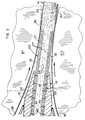
- FIG. 5 is an oblique top view of a portion of a nozzle embodying the present invention. In this view, the reader is looking somewhat upstream and can see the outlet ends of molten-metal-feeding passageways which exit at the discharge (downstream) end of the nozzle.
- FIG. 1 is a side elevational diagrammatic view of a twin-belt continuous caster.
- Such a twin-belt continuous caster is shown in detail in U.S. Patents 4,593,742 and 4,648,438, in FIG. 2 therein. The reader is referred to the disclosures of these two patents if the reader wishes to know more of the details about a typical twin-belt continuous caster.
- a tundish 10 contains molten metal 12 .
- the tundish 10 rests on a supporting fixture 14 which, together with the tundish, is discussed in more detail in the referenced U.S. patents.
- Upper nosepiece 16 and lower nosepiece 18 serve for clamping a gas-permeable nozzle 20 between them.
- the upper and lower nosepiece clamps 16 and 18 are made of strong, heat-resistant material, e.g., steel.
- the supporting fixture 14 and the outer casing 21 of the tundish 10 are also made of a strong heat-resistant material, e.g., steel.
- the gas-permeable nozzle 20 is manufactured as a wide nozzle when used for continuously casting wide slab.
- Wide nozzles usually comprise more than one section.
- the widths of these multiple side-by-side sections add up to the desired total nozzle width, corresponding to the width of the desired cast slab product -- for example, more than about 250 millimeters (about 10 inches) wide.
- One typical slab thickness to be twin-belt cast in aluminum alloys is about 0.600 of an inch or about 15 millimeters, though absolute limits for thickness or thinness of twin-belt continuous casting of aluminum slab are not yet known to exist.
- This slab-thickness dimension corresponds approximately to the thickness "T" of the nozzle 20 as shown in FIG. 5 for its sections 22 and 24 .
- an alternative or supplemental means for allowing the liberated gas to escape is a layer 28 of porous material, for example a layer of porous material such as Fiberfrax (R) paper 28 of thickness about 1/8 inch (about 3 mm) (commercially available from Carborundum Co.), may be interposed between the walls of the nozzle 20 and each clamp 16 and 18 .
- This layer 28 is thus formed of bendable, porous, heat-resistant material.
- the nozzle passageways 27 for downstream flow 25 of the molten metal 12 are made as wide and high as may be consistent with the stability of the nozzle walls 32 , in order to reduce turbulence of the flowing molten metal 12 as it is approaching the moving mold M .
- the moving mold M is defined between the moving upper belt 38 and the moving lower belt 40 .
- Rib 34 (FIG. 5 ) is an internal support used to render the nozzle walls 32 stable while disturbing the downstream flow 25 of molten metal as little as possible.
- the discharge (downstream) end 36 of the nozzle 30 protrudes slightly into the region between the belts.
- the twin-belt continuous casting machine 30 includes the pair of revolving endless flexible casting belts 38 and 40 .
- the upper belt 38 revolves around entrance and exit pulley rolls 41 and 42 , respectively, while the lower belt 40 revolves around entrance and exit pulley rolls 43 and 44 , respectively, so that these revolving belts define between themselves a moving mold region M which is carrying the molten metal downstream toward the right in FIG. 1 as shown by the arrows in FIG. 1 .
- twin-belt continuous casting machine 30 shown in FIG. 1 also includes a pair of laterally spaced moving edge dams (not shown) which form the walls of the two sides of the moving mold M , as known in this art.
- the moving mold M usually slopes downwardly somewhat in the downstream direction, as shown, such downward inclination in the downstream direction being less than 25 degrees to the horizontal.
- such moving mold region M is oriented in the downstream direction at a downward angle to horizontal in the range from zero degrees to less than about 25° to horizontal.
- the nozzle 20 fits between the moving casting belts and between these two edge dams with a clearance above, below, and on each side of no more than about 0.050 of an inch (about 1.27 mm). Usually the clearances are less than that figure, thereby providing "closed metal feeding," as discussed above in the Background.
- At least that portion of the nozzle 20 which fits between the belts is sloping downwardly in the downstream direction at substantially the same angle as the moving mold M .
- the refractory materials used for making the gas-permeable walls 32 of the nozzle 20 in its sectional parts 22 and 24 that are known to be successful contain one or more of the following: fibers of silica, fibers of alumina, and a boron compound. These fibers are felted, intertwined together and are cohered together in their intertwined relationship.
- the fibers are ceramic, strictly speaking, though the resulting gas-permeable walls 32 , or the entire nozzle 20 , are very different in mechanical and physical characteristics from ordinary ceramic; hence, I prefer not to use the name "ceramic" to describe the novel nozzle, nor to describe its gas-permeable walls.
- a suitable material for making a nozzle 20 having gas-permeable walls 32 must be relatively non-wettable by whatever molten metal 12 is to be fed through the nozzle passageways 27 .
- the resulting gas-permeable walls 32 have interconnected voids or interstitial porosity 46 (FIG. 3 ) with interconnected void interstices of such size as to be permeable to the liberated gas 48 while these interconnected interstices 46 are sufficiently small to be non-passable to the molten metal 12 being fed.
- the nozzle walls 32 must retain these desired characteristics for a reasonable term of usefulness against the heat and corrosivity of the molten metal 12 flowing 25 through the passageways 27 .
- These novel nozzle walls 32 have high thermal insulativity.
- Kaowool TBM 2240 commercially available from Thermal Ceramics Inc., Augusta, Georgia.
- This board contains a major volume-percentage of void space between its constituent fibers; i.e., more than 50 percent of the total volume of this board comprises interstitial voids such that the fibers and the interconnected void space interlace with each other and allow gas 48 , liberated from the flowing 25 molten metal 12 to travel outwardly and escape through the interconnected porosity 46 of the nozzle walls 32 .
- the fibers in this gas-permeable refractory board are cohered together, forming so to speak a matrix for the interconnected porous void space 46 .
- the advantage of this heavier material is that of greater strength, which in turn permits the use of thinner walls 32 and hence the casting of correspondingly thinner slab.
- the bulk density range given above is great enough to afford desired strength for the nozzle 20 but small enough to leave the majority of the volume of the refractory material 32 as interconnected interstitial void space 46 .
- This void space 46 insulates the molten metal against premature solidification. Also, and very important, it affords interconnected porosity or gas-permeability, enabling gas 48 evolved from the molten metal 12 flowing 25 through the nozzle passageways 27 to escape from the nozzle 20 through the nozzle walls 32 without entering the moving mold region M .
- the fibers of the suitable materials present under the microscope the appearance of being sintered or otherwise cohered together. At any rate, the joining of fibers into a matrix for the void space greatly increases their collective strength in the refractory material without significantly increasing their weight.
- fibrous refractory materials afford a number of other advantages.
- these fibrous materials are readily machined to relatively precise dimensions by the use of commercially available abrading or cutting tools studded with diamond dust.
- machining is advantageously accomplished without creating surface cracks, such as sometimes occurred in the prior art. (Care must be taken to exhaust and filter all the airborne dust to remove it from the work area where such machining is done.)
- such materials may be molded to the net desired nozzle section shapes, or near to them, so as to minimize machining to final dimensions.
- the aforesaid fibrous materials possess a modicum of flexibility, more so than prior-art dense, non-permeable refractory nozzles, which are apt to crack when clamped between parallel rigid clamps 16 and 18 .
- This flexibility of the porous gas-permeable refractory materials plus their advantageously low thermal expansivity, evidently underlies their inherent thermal shock resistance and their dimensional stability under the severe thermal conditions encountered in feeding molten metal.
- Prior-art undesirable experience with the clamping of dense, non-permeable refractory nozzles shows that such flexibility is especially desirable in clamping of nozzles having a width in excess of about 10 inches (about 250 mm).
- the present invention may be useful additionally for feeding molten metal into twin-carriage caterpillar-block continuous casting machines which define a moving mold region that does not slope downwardly in the downstream direction at an angle of inclination to horizontal so much as 25 degrees.
- a moving mold region if it slopes at all, is oriented in the downstream direction at an angle to horizontal in the range from zero degrees to less than about 25 degrees to horizontal.
- the invention was employed most significantly in an all-day experimental cast of AA 3105 aluminum under conditions formerly resulting in gross voids of about 1/4 inch (6 millimeters) in diameter. No such voids were experienced on this occasion. An unexpected bonus was improved appearance of the cast surface of the resulting slab.
- This experimental aluminum slab had a thickness of about 0.600 of an inch (about 15 mm) and had a width of about 16 inches (about 400 mm).
- the nozzle material is mentioned in column 1, line 32 therein as being ceramic.
- the present invention enables such conventional kinds of ceramic nozzles to be replaced with novel gas-permeable refractory nozzles, as disclosed herein.
- the nozzle alignment art of U.S. Patent 4,830,089 is not part of the present invention.
- Such nozzle alignment apparatus is useful mainly in the casting of metals of higher melting point, in which preheating of metal-feeding nozzles, etc., is required to an extent that cannot be carried out next to metal casting belts.
Landscapes
- Engineering & Computer Science (AREA)
- Mechanical Engineering (AREA)
- Continuous Casting (AREA)
- Extrusion Moulding Of Plastics Or The Like (AREA)
Claims (13)
- Verfahren zum Einspeisen von geschmolzenem Metall (12) durch eine Speisungsdüse (20) zum Einspeisen von geschmolzenem Metall in einen sich bewegenden Kokillenbereich (M) einer Stranggießmaschine (30), gekennzeichnet durch:
Entweichenlassen von aus dem geschmolzenen Metall in einem Durchgang freigesetztem Gas (48) durch Zwischenräume (46) in den Düsenwänden (32) aus gasdurchlässigem, feuerfestem Material. - Speisungsdüse (20) für geschmolzenes Metall zum Einspeisen von geschmolzenem Metall (12) in einen sich bewegenden Kokillenbereich (M) einer Stranggießmaschine (30) mit mehreren Düsenwänden (32) aus feuerfestem Material, die mindestens einen Metallspeisungsdurchgang (27) bilden, dadurch gekennzeichnet, daß
das feuerfeste Material der Düsenwände (32) Einrichtungen (46) aufweist, die das aus dem durch die Durchgänge (27) strömenden (25) geschmolzenen Metall freigesetzte Gas (48) durch die Wände entweichen lassen. - Speisungsdüse für geschmolzenes Metall nach Anspruch 2, gekennzeichnet durch:
an die Düsenwände angrenzende Stützeinrichtungen (16, 18) mit Einrichtungen (26 oder 28), die das durch das gasdurchlässige, feuerfeste Material der Düsenwände gelangende Gas (48) aus der Düse entweichen lassen. - Speisungsdüse für geschmolzenes Metall nach Anspruch 3, dadurch gekennzeichnet, daß:
die Stützeinrichtungen Einspanneinrichtungen (16, 18) an gegenüberliegenden Seiten der Düse (20) aufweisen, die die Düse (20) zwischen den Einspanneinrichtungen (16, 18) angeordnet halten, und die
Einrichtungen (26 oder 28), die das durch das gasdurchlässige Material der Düsenwände (32) gelangende Gas (48) aus der Düse entwelchen lasen, an eine Außenfläche der Düse (20) angrenzen. - Speisungsdüse für geschmolzenes Metall nach Anspruch 4, wobei:
die an die Außenfläche der Düse (20) angrenzenden Einrichtungen mehrere Entlastungsaussparungen (26) sind, die der Düse zugewandt sind. - Speisungsdüse für geschmolzenes Metall nach Anspruch 5, wobei:
die Düse (20) eine Breite aufweist, die größer als etwa 250 mm (etwa 10 Zoll) ist und die Entlastungsaussparungen (26) in den Einspanneinrichtungen (16, 18) über und unter der Düse (20) angeordnet sind und einer oberen und einer unteren Außenfläche der Düse (20) zugewandt sind. - Speisungsdüse für geschmolzenes Metall nach Anspruch 5 oder 6, dadurch gekennzeichnet, daß:
die Düsenwände (32) mehrere im wesentlichen parallele Metallspeisungsdurchgänge (27) bilden, und
die mehreren Entlastungsaussparungen (26) sich im allgemeinen in rechten Winkeln bis zu den mehreren Metallspeisungsdurchgängen (27) erstrecken. - Speisungsdüse für geschmolzenes Metall nach einem der Ansprüche 3 bis 7, wobei:
die Einrichtungen (16, 18), die an die Außenfläche der Düse (20) angrenzen, eine Schicht aus porösem, hitzebeständigen Material (28) aufweisen, die an eine Außenfläche der Düse (20) angrenzend angeordnet ist. - Speisungsdüse für geschmolzenes Metall nach einem der Ansprüche 4 bis 8, wobei:
die an die Düse angrenzenden Einrichtungen zum Entweichenlassen des durch das gasdurchlässige, feuerfeste Material der Düsenwände (32) gelangenden Gases (48) aus der Düse (20) zwei Schichten aus porösem, hitzebeständigem Material (28) aufweisen,
wobei eine der beiden Schichten zwischen einer Wand (32) der Düse (20) und der Einspanneinrichtung (16) angeordnet ist und
die andere der beiden Schichten zwischen einer gegenüberliegenden Wand (32) der Düse (20) und der Einspanneinrichtung (18) angeordnet ist. - Speisungsdüse für geschmolzenes Metall nach Anspruch 8 oder 9, wobei:
die Schicht aus porösem, wärmebeständigem Material (28) etwa 3 mm (etwa 1/8 Zoll) dick ist. - Speisungsdüse für geschmolzenes Metall nach Anspruch 8, 9 oder 10, wobei:
die Düse (20) eine Breite aufweist, die größer als etwa 250 mm (etwa 10 Zoll) ist,
die Einspanneinrichtungen (16, 18) über und unter der Düse (20) angeordnet sind,
eine der beiden Schichten (28) an eine obere Außenfläche der Düse (20) angrenzt und
die andere der beiden Schichten (28) an eine untere Außenfläche der Düse (20) angrenzt. - Speisungsdüse für geschmolzenes Metall nach Anspruch 11, wobei:
jede der beiden Schichten (28) aus porösem, hitzebeständigem Material (28) etwa 3 mm (etwa 1/8 Zoll) dick ist. - Speisungsdüse für geschmolzenes Metall nach einem der Ansprüche 2 bis 12, ferner dadurch gekennzeichnet, daß:
die Gasdurchlässigkeit des feuerfesten Materials das freigesetzte Gas (48) durch die Düsenwände (32) gelangen läßt und verhindert, daß geschmolzenes Metall (12) durch die Düsenwände (32) gelangt.
Applications Claiming Priority (2)
| Application Number | Priority Date | Filing Date | Title |
|---|---|---|---|
| US426096 | 1989-10-24 | ||
| US07/426,096 US4972900A (en) | 1989-10-24 | 1989-10-24 | Permeable nozzle method and apparatus for closed feeding of molten metal into twin-belt continuous casting machines |
Publications (3)
| Publication Number | Publication Date |
|---|---|
| EP0424837A2 EP0424837A2 (de) | 1991-05-02 |
| EP0424837A3 EP0424837A3 (en) | 1993-02-24 |
| EP0424837B1 true EP0424837B1 (de) | 1997-05-02 |
Family
ID=23689268
Family Applications (1)
| Application Number | Title | Priority Date | Filing Date |
|---|---|---|---|
| EP90120196A Expired - Lifetime EP0424837B1 (de) | 1989-10-24 | 1990-10-22 | Verfahren und Einrichtung mit einer durchlässigen Düse für die geschlossene Versorgung von geschmolzenem Metall in Doppelband-Stranggiessanlagen |
Country Status (5)
| Country | Link |
|---|---|
| US (1) | US4972900A (de) |
| EP (1) | EP0424837B1 (de) |
| AT (1) | ATE152379T1 (de) |
| CA (1) | CA2028323C (de) |
| DE (1) | DE69030610T2 (de) |
Cited By (1)
| Publication number | Priority date | Publication date | Assignee | Title |
|---|---|---|---|---|
| DE102017221109A1 (de) | 2016-11-29 | 2018-05-30 | Sms Group Gmbh | Gießdüse |
Families Citing this family (18)
| Publication number | Priority date | Publication date | Assignee | Title |
|---|---|---|---|---|
| ES2123743T3 (es) * | 1993-05-18 | 1999-01-16 | Pechiney Rhenalu | Maquina para la colada en banda de metales. |
| CA2128398C (en) * | 1994-07-19 | 2007-02-06 | John Sulzer | Process and apparatus for casting metal strip and injector used therefor |
| TW300861B (de) * | 1995-05-02 | 1997-03-21 | Baker Refractories | |
| US5799720A (en) * | 1996-08-27 | 1998-09-01 | Ajax Magnethermic Corp. | Nozzle assembly for continuous caster |
| US5860575A (en) * | 1996-09-30 | 1999-01-19 | Akin; James Sherill | Stability enhancement of molten solder droplets as ejected from a nozzle of droplet pump |
| US5742660A (en) * | 1997-01-10 | 1998-04-21 | Southeastern Universities Research Association, Inc. | Dual energy scanning beam laminographic x-radiography |
| US6764559B2 (en) * | 2002-11-15 | 2004-07-20 | Commonwealth Industries, Inc. | Aluminum automotive frame members |
| US20080202646A1 (en) * | 2004-08-27 | 2008-08-28 | Zhong Li | Aluminum automotive structural members |
| US20060042727A1 (en) * | 2004-08-27 | 2006-03-02 | Zhong Li | Aluminum automotive structural members |
| US20080041501A1 (en) * | 2006-08-16 | 2008-02-21 | Commonwealth Industries, Inc. | Aluminum automotive heat shields |
| ES2343581T3 (es) * | 2006-12-14 | 2010-08-04 | Mkm Mansfelder Kupfer Und Messing Gmbh | Procedimiento y dispositivo para la fabricacion de bandas anchas de cobre o aleaciones de cobre. |
| DE102009012985A1 (de) * | 2009-03-12 | 2010-09-23 | Salzgitter Flachstahl Gmbh | Gießdüse für eine horizontale Bandgießanlage |
| US7888158B1 (en) * | 2009-07-21 | 2011-02-15 | Sears Jr James B | System and method for making a photovoltaic unit |
| US20110036531A1 (en) * | 2009-08-11 | 2011-02-17 | Sears Jr James B | System and Method for Integrally Casting Multilayer Metallic Structures |
| US20110036530A1 (en) * | 2009-08-11 | 2011-02-17 | Sears Jr James B | System and Method for Integrally Casting Multilayer Metallic Structures |
| NL2004209C2 (en) * | 2010-02-08 | 2011-08-09 | Rgs Dev B V | Apparatus and method for the production of semiconductor material foils. |
| CN102933334B (zh) * | 2010-06-04 | 2016-11-02 | 住友电气工业株式会社 | 复合材料、连续铸造用部件、连续铸造用喷嘴、连续铸造方法、铸造材料和镁合金铸造卷材 |
| CN114951628B (zh) * | 2021-02-24 | 2024-04-05 | 宝山钢铁股份有限公司 | 一种连铸浸入式水口夹持系统及方法 |
Family Cites Families (12)
| Publication number | Priority date | Publication date | Assignee | Title |
|---|---|---|---|---|
| US3430683A (en) * | 1967-01-12 | 1969-03-04 | American Metal Climax Inc | Feed tip for continuous strip casting machine |
| DE2703657C2 (de) * | 1977-01-28 | 1979-01-25 | Buescher Kg, 5620 Velbert | Steigrohr zum Gießen von Metallen unter Gasdruck |
| CH633205A5 (de) * | 1978-01-30 | 1982-11-30 | Alusuisse | Vorrichtung zum zufuehren einer metallschmelze beim bandgiessen. |
| US4648438A (en) * | 1982-04-28 | 1987-03-10 | Hazelett Strip-Casting Corporation | Method and apparatus for feeding and continuously casting molten metal with inert gas applied to the moving mold surfaces and to the entering metal |
| US4593742A (en) * | 1982-04-28 | 1986-06-10 | Hazelett Strip-Casting Corporation | Apparatus for feeding and continuously casting molten metal with inert gas applied to the moving mold surfaces and to the entering metal |
| CA1208412A (en) * | 1982-04-28 | 1986-07-29 | Robert W. Hazelett | Methods and apparatus for feeding and continuously casting molten metal with inert gas applied to the moving mold surfaces and to the entering metal |
| US4605594A (en) * | 1984-08-08 | 1986-08-12 | Minnesota Mining And Manufacturing Company | Ceramic articles having a nonporous core and porous outer layer |
| US4752515A (en) * | 1985-06-17 | 1988-06-21 | Mitsubishi Chemical Industries | Alumina fiber structure |
| US4770935A (en) * | 1986-08-08 | 1988-09-13 | Ube Industries, Ltd. | Inorganic fibrous material as reinforcement for composite materials and process for production thereof |
| EP0306751B1 (de) * | 1987-09-07 | 1994-06-29 | DANIELI & C. OFFICINE MECCANICHE S.p.A. | Giessverfahren für eine Stranggiessvorrichtung mit reduzierter Bauhöhe und entsprechender Tauchausguss |
| US4811781A (en) * | 1988-03-17 | 1989-03-14 | Hunter Engineering Company, Inc. | Feed tip and continuous casting method using the feed tip |
| US4830089A (en) * | 1988-05-05 | 1989-05-16 | Hazelett Strip-Casting Corporation | Method and apparatus for setting precise nozzle/belt and nozzle/edge dam block gaps |
-
1989
- 1989-10-24 US US07/426,096 patent/US4972900A/en not_active Expired - Lifetime
-
1990
- 1990-10-22 EP EP90120196A patent/EP0424837B1/de not_active Expired - Lifetime
- 1990-10-22 AT AT90120196T patent/ATE152379T1/de not_active IP Right Cessation
- 1990-10-22 DE DE69030610T patent/DE69030610T2/de not_active Expired - Lifetime
- 1990-10-23 CA CA002028323A patent/CA2028323C/en not_active Expired - Lifetime
Cited By (3)
| Publication number | Priority date | Publication date | Assignee | Title |
|---|---|---|---|---|
| DE102017221109A1 (de) | 2016-11-29 | 2018-05-30 | Sms Group Gmbh | Gießdüse |
| WO2018099834A1 (de) | 2016-11-29 | 2018-06-07 | Sms Group Gmbh | GIEßDÜSE |
| US11052457B2 (en) | 2016-11-29 | 2021-07-06 | Sms Group Gmbh | Casting nozzle |
Also Published As
| Publication number | Publication date |
|---|---|
| DE69030610D1 (de) | 1997-06-05 |
| EP0424837A2 (de) | 1991-05-02 |
| EP0424837A3 (en) | 1993-02-24 |
| DE69030610T2 (de) | 1997-08-14 |
| ATE152379T1 (de) | 1997-05-15 |
| CA2028323A1 (en) | 1991-04-25 |
| US4972900A (en) | 1990-11-27 |
| CA2028323C (en) | 1999-05-04 |
Similar Documents
| Publication | Publication Date | Title |
|---|---|---|
| EP0424837B1 (de) | Verfahren und Einrichtung mit einer durchlässigen Düse für die geschlossene Versorgung von geschmolzenem Metall in Doppelband-Stranggiessanlagen | |
| US20090269239A1 (en) | Process for Production of Aluminum Ingots, Aluminum Ingots, and Protective Gas for the Production of Aluminum Ingots | |
| EP1420096A1 (de) | Vorrichtung zur herstellung eines vliesstoffs aus metallfasern, verfahren zu dessen herstellung sowie verfahren zur herstellung eines aluminiumlaminats | |
| KR100605326B1 (ko) | 가압 소결 복합 재료 | |
| CA1227032A (en) | Composite refractory product | |
| KR100607428B1 (ko) | 냉각 요소 제조용 주조 몰드 및 그 몰드에서 제조되는냉각 요소 | |
| CA1208412A (en) | Methods and apparatus for feeding and continuously casting molten metal with inert gas applied to the moving mold surfaces and to the entering metal | |
| US6173755B1 (en) | Nozzle for continuous slab casting | |
| JP2007513773A (ja) | 金属の水平連続鋳造 | |
| US4649984A (en) | Method of and apparatus for casting metal strip employing a localized conditioning shoe | |
| JP2007507351A (ja) | 鋼ストリップ鋳造 | |
| CA1181922A (en) | Apparatus for strip casting | |
| EP0348227B1 (de) | Begrenzungswand für Bandstranggiessanlagen | |
| JP6859827B2 (ja) | スカム堰、双ロール式連続鋳造装置、及び、薄肉鋳片の製造方法 | |
| KR20050057141A (ko) | 가스 퍼징 노즐 | |
| KR20070051785A (ko) | 제강을 위한 지르코니아질 내화물질 | |
| US10926320B2 (en) | Transition plate | |
| CA1064675A (en) | Continuous casting of molten metal | |
| JP2001129643A (ja) | 連続鋳造方法および鋳型 | |
| GB2140720A (en) | Feeding molten metal through a nozzle to a casting mould | |
| US4589472A (en) | Process for preventing metal penetrating between a mold wall and a nozzle | |
| JP2938746B2 (ja) | 溶融金属排出用プレート | |
| JPH04178249A (ja) | 連続鋳造鋳型内の潤滑方法 | |
| JPH08155601A (ja) | 連続鋳造用ノズル | |
| US3926248A (en) | Orifice structure for extruding molten metal to form fine diameter wire |
Legal Events
| Date | Code | Title | Description |
|---|---|---|---|
| PUAI | Public reference made under article 153(3) epc to a published international application that has entered the european phase |
Free format text: ORIGINAL CODE: 0009012 |
|
| 17P | Request for examination filed |
Effective date: 19901228 |
|
| AK | Designated contracting states |
Kind code of ref document: A2 Designated state(s): AT BE DE FR GB IT |
|
| PUAL | Search report despatched |
Free format text: ORIGINAL CODE: 0009013 |
|
| AK | Designated contracting states |
Kind code of ref document: A3 Designated state(s): AT BE DE FR GB IT |
|
| 17Q | First examination report despatched |
Effective date: 19940930 |
|
| GRAG | Despatch of communication of intention to grant |
Free format text: ORIGINAL CODE: EPIDOS AGRA |
|
| GRAG | Despatch of communication of intention to grant |
Free format text: ORIGINAL CODE: EPIDOS AGRA |
|
| GRAH | Despatch of communication of intention to grant a patent |
Free format text: ORIGINAL CODE: EPIDOS IGRA |
|
| GRAH | Despatch of communication of intention to grant a patent |
Free format text: ORIGINAL CODE: EPIDOS IGRA |
|
| GRAA | (expected) grant |
Free format text: ORIGINAL CODE: 0009210 |
|
| AK | Designated contracting states |
Kind code of ref document: B1 Designated state(s): AT BE DE FR GB IT |
|
| REF | Corresponds to: |
Ref document number: 152379 Country of ref document: AT Date of ref document: 19970515 Kind code of ref document: T |
|
| REF | Corresponds to: |
Ref document number: 69030610 Country of ref document: DE Date of ref document: 19970605 |
|
| ET | Fr: translation filed | ||
| PLBE | No opposition filed within time limit |
Free format text: ORIGINAL CODE: 0009261 |
|
| STAA | Information on the status of an ep patent application or granted ep patent |
Free format text: STATUS: NO OPPOSITION FILED WITHIN TIME LIMIT |
|
| 26N | No opposition filed | ||
| REG | Reference to a national code |
Ref country code: GB Ref legal event code: IF02 |
|
| PGFP | Annual fee paid to national office [announced via postgrant information from national office to epo] |
Ref country code: AT Payment date: 20091013 Year of fee payment: 20 Ref country code: DE Payment date: 20091015 Year of fee payment: 20 |
|
| PGFP | Annual fee paid to national office [announced via postgrant information from national office to epo] |
Ref country code: GB Payment date: 20091021 Year of fee payment: 20 Ref country code: IT Payment date: 20091020 Year of fee payment: 20 Ref country code: FR Payment date: 20091029 Year of fee payment: 20 |
|
| PGFP | Annual fee paid to national office [announced via postgrant information from national office to epo] |
Ref country code: BE Payment date: 20091019 Year of fee payment: 20 |
|
| BE20 | Be: patent expired |
Owner name: *HAZELETT STRIP-CASTING CORP. Effective date: 20101022 |
|
| REG | Reference to a national code |
Ref country code: GB Ref legal event code: PE20 Expiry date: 20101021 |
|
| PG25 | Lapsed in a contracting state [announced via postgrant information from national office to epo] |
Ref country code: GB Free format text: LAPSE BECAUSE OF EXPIRATION OF PROTECTION Effective date: 20101021 |
|
| PG25 | Lapsed in a contracting state [announced via postgrant information from national office to epo] |
Ref country code: DE Free format text: LAPSE BECAUSE OF EXPIRATION OF PROTECTION Effective date: 20101022 |