EP0424868B1 - Système de traction pour moteurs de véhicule - Google Patents
Système de traction pour moteurs de véhicule Download PDFInfo
- Publication number
- EP0424868B1 EP0424868B1 EP90120282A EP90120282A EP0424868B1 EP 0424868 B1 EP0424868 B1 EP 0424868B1 EP 90120282 A EP90120282 A EP 90120282A EP 90120282 A EP90120282 A EP 90120282A EP 0424868 B1 EP0424868 B1 EP 0424868B1
- Authority
- EP
- European Patent Office
- Prior art keywords
- motor
- series
- drive system
- electrical drive
- accelerator depression
- Prior art date
- Legal status (The legal status is an assumption and is not a legal conclusion. Google has not performed a legal analysis and makes no representation as to the accuracy of the status listed.)
- Expired - Lifetime
Links
- 230000000994 depressogenic effect Effects 0.000 description 2
- 230000004044 response Effects 0.000 description 2
- 230000001133 acceleration Effects 0.000 description 1
- 150000001875 compounds Chemical class 0.000 description 1
- 238000001514 detection method Methods 0.000 description 1
- 238000010586 diagram Methods 0.000 description 1
- 238000000034 method Methods 0.000 description 1
- 239000007858 starting material Substances 0.000 description 1
- 238000011144 upstream manufacturing Methods 0.000 description 1
Images





Classifications
-
- H—ELECTRICITY
- H02—GENERATION; CONVERSION OR DISTRIBUTION OF ELECTRIC POWER
- H02P—CONTROL OR REGULATION OF ELECTRIC MOTORS, ELECTRIC GENERATORS OR DYNAMO-ELECTRIC CONVERTERS; CONTROLLING TRANSFORMERS, REACTORS OR CHOKE COILS
- H02P7/00—Arrangements for regulating or controlling the speed or torque of electric DC motors
- H02P7/06—Arrangements for regulating or controlling the speed or torque of electric DC motors for regulating or controlling an individual DC dynamo-electric motor by varying field or armature current
- H02P7/08—Arrangements for regulating or controlling the speed or torque of electric DC motors for regulating or controlling an individual DC dynamo-electric motor by varying field or armature current by manual control without auxiliary power
- H02P7/10—Arrangements for regulating or controlling the speed or torque of electric DC motors for regulating or controlling an individual DC dynamo-electric motor by varying field or armature current by manual control without auxiliary power of motor field only
- H02P7/12—Switching field from series to shunt excitation or vice versa
-
- B—PERFORMING OPERATIONS; TRANSPORTING
- B60—VEHICLES IN GENERAL
- B60L—PROPULSION OF ELECTRICALLY-PROPELLED VEHICLES; SUPPLYING ELECTRIC POWER FOR AUXILIARY EQUIPMENT OF ELECTRICALLY-PROPELLED VEHICLES; ELECTRODYNAMIC BRAKE SYSTEMS FOR VEHICLES IN GENERAL; MAGNETIC SUSPENSION OR LEVITATION FOR VEHICLES; MONITORING OPERATING VARIABLES OF ELECTRICALLY-PROPELLED VEHICLES; ELECTRIC SAFETY DEVICES FOR ELECTRICALLY-PROPELLED VEHICLES
- B60L50/00—Electric propulsion with power supplied within the vehicle
- B60L50/50—Electric propulsion with power supplied within the vehicle using propulsion power supplied by batteries or fuel cells
- B60L50/52—Electric propulsion with power supplied within the vehicle using propulsion power supplied by batteries or fuel cells characterised by DC-motors
-
- B—PERFORMING OPERATIONS; TRANSPORTING
- B60—VEHICLES IN GENERAL
- B60L—PROPULSION OF ELECTRICALLY-PROPELLED VEHICLES; SUPPLYING ELECTRIC POWER FOR AUXILIARY EQUIPMENT OF ELECTRICALLY-PROPELLED VEHICLES; ELECTRODYNAMIC BRAKE SYSTEMS FOR VEHICLES IN GENERAL; MAGNETIC SUSPENSION OR LEVITATION FOR VEHICLES; MONITORING OPERATING VARIABLES OF ELECTRICALLY-PROPELLED VEHICLES; ELECTRIC SAFETY DEVICES FOR ELECTRICALLY-PROPELLED VEHICLES
- B60L2250/00—Driver interactions
- B60L2250/26—Driver interactions by pedal actuation
-
- Y—GENERAL TAGGING OF NEW TECHNOLOGICAL DEVELOPMENTS; GENERAL TAGGING OF CROSS-SECTIONAL TECHNOLOGIES SPANNING OVER SEVERAL SECTIONS OF THE IPC; TECHNICAL SUBJECTS COVERED BY FORMER USPC CROSS-REFERENCE ART COLLECTIONS [XRACs] AND DIGESTS
- Y02—TECHNOLOGIES OR APPLICATIONS FOR MITIGATION OR ADAPTATION AGAINST CLIMATE CHANGE
- Y02T—CLIMATE CHANGE MITIGATION TECHNOLOGIES RELATED TO TRANSPORTATION
- Y02T10/00—Road transport of goods or passengers
- Y02T10/60—Other road transportation technologies with climate change mitigation effect
- Y02T10/64—Electric machine technologies in electromobility
-
- Y—GENERAL TAGGING OF NEW TECHNOLOGICAL DEVELOPMENTS; GENERAL TAGGING OF CROSS-SECTIONAL TECHNOLOGIES SPANNING OVER SEVERAL SECTIONS OF THE IPC; TECHNICAL SUBJECTS COVERED BY FORMER USPC CROSS-REFERENCE ART COLLECTIONS [XRACs] AND DIGESTS
- Y02—TECHNOLOGIES OR APPLICATIONS FOR MITIGATION OR ADAPTATION AGAINST CLIMATE CHANGE
- Y02T—CLIMATE CHANGE MITIGATION TECHNOLOGIES RELATED TO TRANSPORTATION
- Y02T10/00—Road transport of goods or passengers
- Y02T10/60—Other road transportation technologies with climate change mitigation effect
- Y02T10/70—Energy storage systems for electromobility, e.g. batteries
Definitions
- This invention relates to an electrical drive system comprising a d.c. motor for driving a vehicle.
- the system has a motor-type selection means for selecting the type of the vehicle motor among a series motor, a compound-wound motor and a shunt motor.
- a vehicle motor is mostly driven by a battery installed in a vehicle, particularly an electric vehicle which has been developed for being free from oil resource and less pollution. Control of such a motor is one of the important factors in determining the vehicle performance.
- the Japanese Utility Model Publication No. 1983(58)-21284 discloses such motor control.
- the control apparatus disclosed therein comprises a feeder circuit including a controller for adjusting the voltage or current applied to the motor in response to an amount of depression of an accelerator.
- the apparatus comprises a brake circuit for braking the motor by short-circuiting two terminals of the motor and a switch interlocked by the accelerator for switching the two circuits.
- the feeder circuit is driven to rotate the motor when the accelerator is depressed.
- the brake circuit is driven to brake the motor when the accelerator is released.
- a motor driven by means of a d.c. current from a battery is roughly classified into a series motor, a compound-wound motor and a shunt motor according to a wiring configuration of coils for exciting field poles.
- Those motors are selectively used for their usage. However, only one type of a motor is sometimes not sufficient for a vehicle such as an electric vehicle which should be operated at various travelling conditions.
- the series motor produces a large starting torque and excellent starting acceleration but also has a large speed variation and increases the engine speed greatly when the load torque to the motor is made small.
- the shunt motor has a low speed variation or stable engine speed even if the load torque varies but also has relatively a small speed control region when a load is connected thereto.
- the compound-wound motor has characteristics intermediate between the series motor and the shunt motor and a slow response to the change of the operating state.
- An electrical drive system in accordance with the preamble of claim 1 is known from EP-A-0 129 319.
- the motor control circuit includes a second switching means connected in series with the series coil. Both switching means are implemented by choppers.
- the motor control circuit responds to speed selection settings to operate the second switching means intermittently while holding the first switching means closed over a lower speed range, and to operate the first switching means intermittently while holding the second switching means closed over a higher speed range, in order to provide a multiple-range speed control system for a compound motor.
- US-A-3,755,724 discloses a control circuit for a d.c. electric motor selectively operable as a series motor and as a shunt motor.
- the circuit includes means to switch connections of the motor armature and of the motor field to adapt such connections to assure the proper armature commutation under predetermined load conditions.
- the object of the present invention is to provide an electrical drive system which switches the type of a vehicle motor according to travelling conditions to obtain best motor characteristics so as to improve vehicle performance.
- the vehicle motor has an armature coil, a series circuit including a series coil and connecting the amature coil and a battery and a shunt coil, said system comprising a first switch for connecting the shunt coil to the series circuit in parallel to the armature coil to set up the motor as a compound-wound motor when the shunt coil is connected to the series circuit, while setting up the motor as a series motor when disconnected therefrom, and comprising a second switch for disconnecting the series coil from the series circuit to set up the motor as a shunt motor when the shunt coil is connected to the series circuit and the series circuit is disconneted therefrom.
- an electric automobile 1 comprises an engine 2 having a crankshaft pulley 2a to which a pulley 4a of a generator 4 is connected through a belt 3.
- a battery 5 is charged by the generator 4.
- the generator 4 also acts as a starter when the engine 2 starts.
- a drive gear 1b mounted on an axle shaft 1a is connected to a drive gear 6d of a motor 6 through an idler gear 7.
- the motor 6 is a d.c. motor.
- the output of the engine 2 is converted into electrical energy.
- the battery 5 is then charged with the electrical energy.
- the motor 6 is thus driven by means of the charged electrical energy.
- the electric automobile 1 is a serial hybrid vehicle.
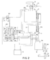
- the engine 2 is a gasoline engine. As is shown in FIG. 2, a carburetor 8 is provided in an intake pipe 7b. An air cleaner 9 is attached to the intake pipe 7b upstream the carburetor 8. Furthermore, a rotary actuator 10 composed of such as a stepping motor or a rotary solenoid is attached to a throttle valve 7a installed in the intake pipe 7b.
- a generator-rotating speed detection sensor 11 which is composed of such as an electromagnetic pickup detecting the protrusions is provided to face the protrusions.
- a controller 20 consisting of a microcomputer comprises a CPU (central processing unit) 21, a ROM (read only memory) 22, a RAM (random access memory) 23 and an I/O (input/output) interface 24 connected to each other through a bus line 25.
- a constant-voltage power supply 26 connected to the battery 5 through a relay contact of a control relay RY supplies electrical power to those components of the controller 20.
- the control relay RY is also connected to the battery 5 through a key switch 27 and an ignition circuit 2b of the engine 2. Furthermore, a generator control circuit 4b and a motor control circuit 6e are connected to the battery 5 to be supplied with the electrical power.
- Various sensors including the generator-rotating speed sensor 11 and an accelerator depression amount sensor 12 are connected to an input port of the I/O interface 24. Also, a positive terminal of the battery 5 is connected to the input port to supply a terminal voltage thereto.
- the rotary actuator 10 the ignition circuit 2b, the generator control circuit 4b and the motor control circuit 6e are connected to an output port of the I/O interface 24 through a drive circuit 28.
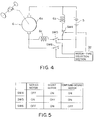
- FIG. 4 shows a preferred embodiment of the invention.
- a shunt coil 6b is connected in parallel to an armature coil 6a of the d.c. motor 6, and a series coil 6c is connected in series to the armature coil 6a.
- a switch SW4 is connected in series to the shunt coil 6b.
- a switch SW5 is connected in series to the series coil 6c.
- a switch SW6 is connected in parallel to a series circuit of the series coil 6c and the switch SW5.
- a motor-type selection section 32 controls a switching means such as the switches SW4, SW5 and SW6 so that the motor 6 operates as a compound-wound motor, a shunt motor or a series motor according to the travelling state.
- the switch SW5 may be eliminated since it is to surely disconnect the series coil 6c from the battery 5.
- the engine 2 in this preferred embodiment of the present invention has a vehicle speed sensor 30 and a current sensor 14 connected to the battery 5 at its positive terminal.
- the sensors 14 and 30 are connected to the input port of the I/O interface 24.
- An alarm LED 15 is connected to the drive circuit 28.
- Other configuration in FIG. 6 is the same as that in FIG. 2.
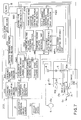
- a motor control circuit 60e will be explained with reference to FIG. 7.
- a field current/voltage adjusting resistor 16 is connected in series to a shunt coil 6b.
- a relay contact (corresponding to the switch SW4 in FIG. 4) of a relay switch SW10 is connected in series to the resistor 16.
- An armature voltage adjusting resistor 13 is connected in series to the series coil 6c.
- a relay contact (corresponding to the switch SW5 in FIG. 4) of a relay switch SW20 is connected in series to the resistor 13.
- a relay contact (corresponding to the switch SW6 in FIG. 4) of a relay switch SW30 is connected in parallel to the series circuit of the series coil 6c, the resistor 13 and the relay contact of the relay switch SW20.
- resistors 13 and 16 are adjusted by resistance-control actuators 13a and 16a, respectively.
- the ROM 22 is prestored with a control program and fixed data such as control data.
- the RAM 23 is stored with data obtained after calculating output signals from each of the sensors and also a monitored value of the terminal voltage of the battery 5.
- Signals from each of the sensors are processed by the CPU 21 according to the control program prestored in the ROM 22. Then, an engine-stop signal to the ignition circuit 2b, a control signal to the generator control circuit 4b, a drive signal to the rotary actuator 10 and a control signal to the control circuit 60e are calculated by the CPU 21.
- the opening of the throttle valve 7a of the engine 2 is controlled by the rotary actuator 10 which is driven by the CPU 21. Furthermore, charging to the battery 5 is controlled by the generator 4 whose rotation speed is adjusted to a specific value by the CPU 21.
- the motor 6 is also switched between the series, the shunt or the compound-wound motor-type by the CPU 21, according to the travelling state of the vehicle 1.
- the controller 200 comprises a consumed-power calculation section 300, a consumed-power judging section 310, an alarm drive section 320, an accelerator depression amount calculation section 330, an accelerator depression amount judging section 340, a consumed current judging section 350, a vehicle speed judging section 360, a battery terminal voltage judging section 370, a motor-type selection section 380, an armature voltage adjusting resistance setting section 390, an armature voltage adjusting resistance map MR2, an armature voltage adjusting resistance-control actuator drive section 400, a field current adjusting resistance setting section 410, a field current adjusting resistance map MR1, a field current adjusting resistance-control actuator drive section 420.
- the consumed power W thus calculated is judged as to whether it is smaller than a specific preset value WSET in the judging section 310.
- the alarm LED 15 is then turned on by the alarm drive section 320 to warn a driver if it is judged in the judging section 310 that the calculated consumed power W exceeds the preset value WSET.
- a depression amount ⁇ is calculated in the calculation section 330 based on a signal from the sensor 12.
- the depression amount ⁇ thus calculated is judged as to whether it is smaller than a specific preset value ⁇ SET or not in the judging section 340 if the calculated consumed power W is judged smaller than the preset value WSET in the judging section 310.
- the consumed current A detected by the sensor 14 is judged as to whether it is larger than a specific preset value ASET or not in the judging section 350 if the calculated depression amount ⁇ is judged larger than the preset value ⁇ SET in the judging section 340.
- a vehicle speed S detected by the sensor 30 is judged as to whether it is smaller than a specific preset value SSET in the judging section 360 if the detected consumed current A is judged to be larger than the preset value ASET in the judging section 350.
- the terminal voltage V B of the battery 5 is judged as to whether it is smaller than a specific preset value VSET in the judging section 370 if the calculated consumed power W is judged to be larger than the preset value WSET in the judging section 310.
- All the judging results of the judging sections 310, 340, 350, 360 and 370 are received by the selection section 380 to select the type of the motor 6 among the series motor-type, the shunt motor-type and the compound-wound motor-type.
- the relay switches SW10 and SW30 are turned off and the relay switch SW20 is turned on in the motor control circuit 60e if the series motor-type is selected.
- the relay switches SW10 and SW30 are turned on and the relay switch SW20 is turned off if the shunt motor-type is selected.
- relay switches SW10 and SW20 are turned on and the relay switch SW30 is turned off if the compound-wound motor-type is selected.
- the motor 6 is set up as the compound-wound motor without any condition to reduce the power consumption if the present consumed power W is larger than the preset value WSET.
- the motor 6 is also set up as the compound-wound motor to restrict power reduction of the battery 5 if the consumed power W and the depression amount ⁇ are smaller than preset values WSET and ⁇ SET, respectively.
- the motor 6 is set up as the series motor under the travelling state that the vehicle speed S is lower than the preset value SSET and a larger torque is required if the consumed power W is smaller than the preset value WSET and the depression amount ⁇ is larger than the preset value ⁇ SET. Furthermore, the motor 6 is set up as the shunt motor under the travelling state that the vehicle speed S is higher than the preset value SSET and a large torque is not required but a stable vehicle speed is required.
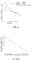
- the motor 6 can be driven under the best condition of the characteristics shown in FIG. 3 according to the travelling state to improve energy efficiency and the travelling performance greatly.
- an armature voltage adjusting resistance R2 of the motor 6 is retrieved from the map MR2 with the depression amount ⁇ calculated by the calculation section 330 as a parameter ⁇ when the motor 6 is set up as the series motor or the compound-wound motor in the selection section 380.
- the actuator 13a is then driven through the drive section 400 to adjust the resistor 13 connected in series to the series coil 6c of the motor 6 to the resistance R2.
- a field current adjusting resistance R1 is retrieved from the map MR1 with the depression amount ⁇ calculated by the calculation section 330 as a parameter ⁇ when the motor 6 is set up as the shunt motor or the compound-wound motor in the selection section 380.
- the actuator 16a is then driven through the drive section 420 to adjust the resistor 16 connected in series to the shunt coil 6b of the motor 6 to the resistance R1.
- the resistance R1 and R2 which are in inverse proportion to the depression amount ⁇ - so as to produce the required torque and vehicle speed - are prestored in the maps MR1 and MR2, respectively.
- the larger the depression amount ⁇ the smaller the resistance R1 and R2 to boost voltages applied to the armature coil 6a and the series coil 6c in the case of the series motor-type.
- the current applied to the shunt coil 6b is made larger and the current applied to the armature coil 6a is made smaller with an increase of the depression amount ⁇ in the case of the shunt motor.
- a combination of the above two cases are brought into the compound-wound motor-type when selected.
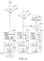
- FIGS. 9 to 11 show a program which is repeated per specific period of time or cycle while the electric vehicle 1 is travelling by the motor 6 which is started by turning on the key switch 27.
- the calculated consumed power W is compared with the preset value WSET in STEP 203.
- the program advances to STEP 219 shown in FIG. 11 if W > WSET.
- the program advances to STEP 204 in which a drive signal is stopped to turn off the alarm LED 15. Then, the program advances to STEP 205.
- the accelerator depression amount ⁇ is accepted in STEP 205.
- the depression amount ⁇ is compared with a preset value ⁇ SET in STEP 206 shown in FIG. 10.
- the program advances to STEP 207 if ⁇ ⁇ ⁇ SET, in which the relay switches SW10 and SW20 are turned on and the relay switch SW30 is turned off to set up the motor 6 as the compound-wound motor-type. Then, the program advances to STEP 208.
- the resistances R1 and R2 are respectively retrieved from the maps MR1 and MR2 with the depression amount ⁇ as a parameter. The program then advances to STEP 209.
- the actuators 16a and 13a are driven to set each of values of the resistors 16 and 13 to the resistances R1 and R2 determined in STEP 208. Then, the program returns to STEP 201.
- the program advances to STEP 210.
- the consumed current A accepted in STEP 201 and a preset value ASET are compared with each other in STEP 210. Then, the program advances to STEP 213 if A ⁇ ASET, while to STEP 211 if A ⁇ ASET.
- the vehicle speed S is accepted from the sensor 30 in STEP 211. Then, the vehicle speed S and a preset value SSET are compared with each other in STEP 212. The program advances to STEP 213 if S ⁇ SSET in STEP 212.
- the resistance R2 is retrieved from the map MR2 with the depression amount ⁇ as a parameter accepted in STEP 205. Then, the program advances to STEP 215.
- the actuator 13a is driven to set the resistor 13 to the resistance R2 determined in STEP 114. Then, the program returns to STEP 201.
- the program advances to STEP 216.
- the relay switches SW10 and SW30 are turned on and the relay switch SW20 is turned off in the motor control circuit 60e to select the shunt motor-type. Then, the program advances to STEP 217.
- the resistance R1 is retrieved from the map MR1 with the depression amount ⁇ as a paramemter accepted in STEP 205.
- the program advances to STEP 218.
- the actuator 16a is driven to set the value of the resistor 16 to the resistance R1 determined in STEP 217. Then, the program returns to STEP 201.
- the program advances to STEP 219 from STEP 203 if the calculated consumed power W is larger than the preset value WSET.
- a depression amount ⁇ from the sensor 12 is accepted in STEP 221 and then in STEP 222, the resistance R1 and R2 are respectively retrieved from the maps MR1 and MR2 with the depression amount ⁇ as a paramemter accepted in STEP 221.
- the program advances to STEP 223.
- the actuaters 16a and 13a are driven to set each of values of the resistors 16 and 13 to the resistance R1 and R2 determined in STEP 222.
- the program then advances to STEP 224.
- the terminal voltage V B is again accepted and then in STEP 225, the terminal voltage V B and the preset reference voltage VSET are compared with each other.
- the program returns to STEP 220 to set the motor to the compound-wound motor-type if V B ⁇ VSET and the program returns to STEP 201 to determine the motor-type again if V B > VSET.
- FIG. 12 shows a further preferred embodiment according to the present invention.
- a field current adjusting resistor 50 connected to the shunt coil 6b of the motor 6 and an armature voltage adjusting resistor 51 connected to the series coil 6c are linked to an accelerator 52 through wires 54a and 54b and a link 53.
- connection of the armature coil 6a to the shunt coil 6b and also the series coil 6c are switched by a switching means composed of an interlocked switch SW40 which is operated by a motor-type selection section 380 according to travelling condition.
- FIG. 12 now represents the compound-wound motor-type.
- the motor 6 is then switched to the shunt motor-type when three contactors of the switch SW40 are switched one stage downward, respectively.
- the motor 6 is switched to the series motor-type when each contactor of the switch SW40 is switched one more stage downward.
- the wires 54a and 54b are pulled through the link 53 when the accelerator 52 is depressed to make values of the resistance 50 and 51 less so as to obtain the required torque and vehicle speed.
- the present invention provides a switching means for switching connection between an armature coil and a series coil and a shunt coil of a vehicle motor according to travelling condition.
- One motor is thus switched to a compound-wound motor-type, a series motor-type or a shunt motor-type to obtain best motor characteristics matching with the travelling condition. Therefore, vehicle performance and cost performance are greatly improved.
Landscapes
- Engineering & Computer Science (AREA)
- Power Engineering (AREA)
- Life Sciences & Earth Sciences (AREA)
- Sustainable Development (AREA)
- Sustainable Energy (AREA)
- Transportation (AREA)
- Mechanical Engineering (AREA)
- Electric Propulsion And Braking For Vehicles (AREA)
Claims (17)
- Système de commande électrique comprenant un moteur à courant continu (6) et une batterie (5), ledit moteur (6) étant monté sur un véhicule pour propulser ledit véhicule avec l'énergie électrique délivrée par la batterie, un circuit de commande du moteur (60e) pour commander ledit moteur, un accélérateur (52) pour ledit véhicule et un moyen de détection de degré d'enfoncement de l'accélérateur (12) pour détecter le degré d'enfoncement de l'accélérateur, ledit moteur (6) comportant un enroulement d'induit (6a) connecté à ladite batterie, un enroulement shunt (6b) connecté à ladite batterie en parallèle audit enroulement d'induit et un enroulement série (6c) connecté à ladite batterie en série avec ledit enroulement d'induit, ledit circuit de commande du moteur (60e) comportant un premier moyen de commutation (SW4 ; SW10) connecté en série avec ledit enroulement shunt, caractérisé par un second moyen de commutation (SW6 ; SW30) connecté en parallèle audit enroulement série (6c) et un moyen de sélection du type de moteur (32 ; 380) pour sélectionner, conformément aux conditions du déplacement, un mode moteur shunt en fermant les deux interrupteur, un mode moteur série en ouvrant les deux interrupteurs et un mode moteur compound en fermant le premier interrupteur et en ouvrant le deuxième interrupteur.
- Système de commande électrique selon la revendication 1, comprenant de plus un troisième moyen de commutation (SW5 ; SW20) connecté en série audit enroulement série (6c), le troisième interrupteur étant fermé en mode moteur série et en mode moteur compound et étant ouvert en mode moteur shunt.
- Système de commande électrique selon la revendication 1 ou 2, comprenant de plus un moyen de détection de tension pour détecter la tension de borne de ladite batterie, un moyen de détection de courant (14) pour détecter le courant délivré audit moteur, un moyen de calcul d'énergie (300) pour calculer l'énergie électrique consommée dudit moteur, (6) basée sur la tension de la borne et ledit courant, un moyen d'évaluation d'énergie (310) pour évaluer si ladite énergie consommée est supérieure à une valeur d'énergie prédéterminée, et ledit moyen de sélection de type de moteur (380) étant adapté afin de sélectionner le mode moteur compound lorsque le moyen d'évaluation d'énergie évalue que ladite énergie consommée est supérieure à ladite valeur d'énergie prédéterminée.
- Système de commande électrique selon la revendication 3, comprenant de plus un avertisseur (15) pour avertir un opérateur lorsque le moyen d'évaluation d'énergie (310) évalue que ladite énergie consommée est supérieure à ladite valeur d'énergie prédéterminée.
- Système de commande électrique selon l'une quelconque des revendications précédentes, dans lequel ledit circuit de commande de moteur (60e) comporte de plus une première résistance variable (16, 50) connectée en série audit enroulement shunt (6a) et audit premier moyen de commutation (SW4 ; SW10) pour faire varier le courant d'inducteur délivré audit enroulement shunt et une seconde résistance variable (13, 51) connectée en série audit enroulement série (6c) pour faire varier la tension appliquée audit enroulement d'induit (6a) et audit enroulement série (6c), les deux résistances étant adaptées pour modifier leurs valeurs en fonction de l'enfoncement de l'accélérateur.
- Système de commande électrique selon la revendication 5, comprenant de plus : un moyen de réglage de valeur ohmique d'ajustement de courant d'inducteur (410) pour régler une première valeur ohmique de ladite première résistance variable (16, 50) sur la base dudit enfoncement de l'accélérateur, lorsque le mode moteur compound est sélectionné et un moyen de réglage de valeur ohmique d'ajustement de tension (390) pour régler une seconde valeur ohmique de ladite seconde résistance variable (13, 51) sur la base dudit enfoncement de l'accélérateur lorsque le mode moteur compound est sélectionné, d'où il résulte que ledit moteur produit le couple requis.
- Système de commande électrique selon la revendication 6, dans lequel ledit moyen de réglage de valeur ohmique d'ajustement de courant d'inducteur (410) comprend une table de correspondance de valeur ohmique d'ajustement de courant d'inducteur (MR1) qui est établie sur la base de la relation inversement proportionnelle de ladite première valeur ohmique avec ledit enfoncement de l'accélérateur.
- Système de commande électrique selon la revendication 6 ou 7, dans lequel ledit moyen de réglage d'une valeur ohmique d'ajustement de tension (390) comprend une table de correspondance d'une valeur ohmique d'ajustement de tension (MR2) qui est établie sur la base de la relation inversement proportionnelle de ladite seconde valeur ohmique avec ledit enfoncement de l'accélérateur.
- Système de commande électrique selon l'une quelconque des revendications 5 à 8, comprenant de plus un moyen de connexion (53) pour connecter chacune de ladite première résistance variable (50) et de ladite seconde résistance variable (51) audit accélérateur (52) afin de modifier les valeurs de chaque résistance en fonction de l'enfoncement de l'accélérateur.
- Système de commande électrique selon l'une quelconque des revendications 3 à 9, comprenant de plus un moyen d'évaluation de la tension de la borne de la batterie (370) pour évaluer si la tension de la borne de la batterie est supérieure à la tension prédéterminée et imposer audit moyen de sélection de type de moteur (380) de maintenir le mode moteur compound lorsque la tension de la borne de la batterie est inférieure à ladite tension prédéterminée.
- Système de commande électrique selon l'une quelconque des revendications 3 à 10, comprenant de plus : un moyen d'évaluation d'enfoncement de l'accélérateur (340) pour évaluer si ledit enfoncement de l'accélérateur est supérieur à une quantité prédéterminée lorsque ledit moyen d'évaluation d'énergie (310) évalue que ladite énergie consommée est plus faible que ladite valeur d'énergie prédéterminée, ledit moyen de sélection de type de moteur (380) étant adapté pour sélectionner ledit mode moteur compound lorsque le moyen d'évaluation d'enfoncement de l'accélérateur évalue que ledit enfoncement de l'accélérateur est inférieur audit degré prédéterminé.
- Système de commande électrique selon l'une quelconque des revendications 3 à 11, comprenant de plus : un moyen d'évaluation de courant (350) pour évaluer si ledit courant est inférieur à une valeur de courant prédéterminée lorsque ledit moyen d'évaluation d'enfoncement de l'accélérateur évalue que ledit enfoncement de l'accélérateur est plus grand que ladite quantité prédéterminée, ledit moyen de sélection du type de moteur (380) étant adapté pour sélectionner le mode moteur série lorsque ledit moyen d'évaluation de courant évalue que ledit courant est inférieur à ladite valeur de courant prédéterminée.
- Système de commande électrique selon la revendication 12, dans lequel ledit moyen de réglage de valeur ohmique d'ajustement de tension (390) est prévu pour fixer ladite seconde valeur ohmique de ladite seconde résistance variable (13 ; 51) sur la base dudit enfoncement de l'accélérateur lorsque ledit mode moteur série est sélectionné, d'où il résulte que ledit moteur produit le couple requis.
- Système de commande électrique selon la revendication 12 ou 13, comprenant de plus : un moyen de détection de vitesse de véhicule (30) pour détecter la vitesse du véhicule, un moyen d'évaluation de vitesse de véhicule (360) pour évaluer si ladite vitesse du véhicule est supérieure à une vitesse prédéterminée lorsque ledit moyen d'évaluation de courant (350) évalue que ledit courant est plus grand que ladite valeur de courant prédéterminée, ledit moyen de sélection de type de moteur (380) étant prévu pour sélectionner le mode moteur shunt lorsque ledit moyen d'évaluation de vitesse du véhicule évalue que ladite vitesse du véhicule est supérieure à ladite vitesse de véhicule prédéterminée.
- Système de commande électrique selon la revendication 14, dans lequel le moyen de sélection de type de moteur (380) est prévu pour sélectionner ledit mode moteur série lorsque ledit moyen d'évaluation de vitesse du véhicule (360) évalue que ladite vitesse du véhicule est inférieure à ladite vitesse du véhicule prédéterminée.
- Système de commande électrique selon la revendication 14, dans lequel ledit moyen de réglage de la valeur ohmique d'ajustement du courant d'inducteur (410) est prévu pour fixer ladite première valeur ohmique de ladite première résistance variable (16, 50) sur la base dudit enfoncement de l'accélérateur lorsque le mode moteur shunt est sélectionné, d'où il résulte que ledit moteur produit le couple requis.
- Système de commande électrique selon la revendication 3, comprenant de plus un moyen de détection de vitesse du véhicule (30) pour détecter la vitesse du véhicule, dans lequel ledit moyen de sélection de type de moteur (380) est prévu pour sélectionner le mode moteur shunt lorsque la vitesse du véhicule détectée est supérieure à une vitesse prédéterminée.
Applications Claiming Priority (4)
| Application Number | Priority Date | Filing Date | Title |
|---|---|---|---|
| JP1278186A JP2871751B2 (ja) | 1989-10-24 | 1989-10-24 | 車輌用モータの切換装置 |
| JP278186/89 | 1989-10-24 | ||
| JP1279106A JPH03143202A (ja) | 1989-10-25 | 1989-10-25 | 車輌用モータの切換装置 |
| JP279106/89 | 1989-10-25 |
Publications (3)
| Publication Number | Publication Date |
|---|---|
| EP0424868A2 EP0424868A2 (fr) | 1991-05-02 |
| EP0424868A3 EP0424868A3 (en) | 1991-06-26 |
| EP0424868B1 true EP0424868B1 (fr) | 1995-02-01 |
Family
ID=26552756
Family Applications (1)
| Application Number | Title | Priority Date | Filing Date |
|---|---|---|---|
| EP90120282A Expired - Lifetime EP0424868B1 (fr) | 1989-10-24 | 1990-10-23 | Système de traction pour moteurs de véhicule |
Country Status (3)
| Country | Link |
|---|---|
| US (1) | US5165006A (fr) |
| EP (1) | EP0424868B1 (fr) |
| DE (1) | DE69016573T2 (fr) |
Families Citing this family (9)
| Publication number | Priority date | Publication date | Assignee | Title |
|---|---|---|---|---|
| DE4128627C2 (de) * | 1991-08-26 | 1994-06-23 | Mannesmann Ag | Verfahren zur Veränderung der Geschwindigkeit eines Fahrzeuges und Fahrzeug zur Durchführung dieses Verfahrens |
| GB2270216A (en) * | 1992-08-28 | 1994-03-02 | Yang Tai Her | Electric motor control circuit |
| US5264763A (en) * | 1992-10-29 | 1993-11-23 | Schaeff Inc. | Optimizing system for vehicle traction motors |
| US5410231A (en) * | 1993-07-08 | 1995-04-25 | Yang; Tai-Her | Auxiliary power supply circuit for a series motor |
| ITMI20032577A1 (it) * | 2003-12-23 | 2005-06-24 | Valerio Accerenzi | Veicolo giocattolo elettrico con aderenza migliorata |
| JP2005323434A (ja) * | 2004-05-07 | 2005-11-17 | Moric Co Ltd | 電動車両 |
| JP2006060959A (ja) * | 2004-08-23 | 2006-03-02 | Moric Co Ltd | 分巻きモータの電流異常検出システム |
| US10300791B2 (en) * | 2015-12-18 | 2019-05-28 | Ge Global Sourcing Llc | Trolley interfacing device having a pre-charging unit |
| US10452045B1 (en) * | 2018-11-30 | 2019-10-22 | Veritone Alpha, Inc. | Controlling ongoing battery system usage while repeatedly reducing power dissipation |
Family Cites Families (7)
| Publication number | Priority date | Publication date | Assignee | Title |
|---|---|---|---|---|
| US3755724A (en) * | 1972-04-03 | 1973-08-28 | Gen Electric | Control for series shunt motor |
| JPS538910A (en) * | 1976-07-14 | 1978-01-26 | Hitachi Ltd | Electric rolling stock controlling device |
| US4114076A (en) * | 1977-04-18 | 1978-09-12 | Nippondenso Co., Ltd. | Control system for a motor having a shunt field winding |
| US4217529A (en) * | 1978-09-19 | 1980-08-12 | Gould Inc. | Propulsion system for electrical vehicle |
| US4551659A (en) * | 1982-10-11 | 1985-11-05 | Markham John D | Trackside-controlled electric railway systems |
| DE3335923A1 (de) * | 1983-03-07 | 1984-09-13 | Volkswagenwerk Ag | Hybrid-antriebsanordnung |
| US4751439A (en) * | 1983-05-16 | 1988-06-14 | Caterpillar Industrial Inc. | Multiple chopper speed control system for compound motor |
-
1990
- 1990-10-23 EP EP90120282A patent/EP0424868B1/fr not_active Expired - Lifetime
- 1990-10-23 US US07/601,134 patent/US5165006A/en not_active Expired - Fee Related
- 1990-10-23 DE DE69016573T patent/DE69016573T2/de not_active Expired - Fee Related
Also Published As
| Publication number | Publication date |
|---|---|
| EP0424868A3 (en) | 1991-06-26 |
| DE69016573D1 (de) | 1995-03-16 |
| EP0424868A2 (fr) | 1991-05-02 |
| US5165006A (en) | 1992-11-17 |
| DE69016573T2 (de) | 1995-09-07 |
Similar Documents
| Publication | Publication Date | Title |
|---|---|---|
| US6018199A (en) | Starter for engine equipped with motor generator | |
| US4641079A (en) | Battery voltage regulating system | |
| US5428274A (en) | Drive control apparatus of series hybrid vehicle | |
| US6426608B2 (en) | Automobile and power supply system therefor | |
| EP0094685B1 (fr) | Dispositif de contrôle de charge avec microcalculateur pour véhicule | |
| US4661760A (en) | Control system for engine-driven generator | |
| CN113002329A (zh) | 用于交通工具的可变电压充电系统和方法 | |
| EP1219492A3 (fr) | Méthode et dispositif de commande adaptable pour l'entraínement hybride d'un véhicule électrique | |
| CA2248619C (fr) | Generateur pour moteur a combustion interne | |
| EP1652716B1 (fr) | Véhicule hybride et procédé de commande de celui-ci | |
| US5165006A (en) | Vehicle motor switching apparatus | |
| US6233396B1 (en) | Load control system for motor | |
| EP0371472B1 (fr) | Système électrique pour véhicule automobile | |
| JPH0746773A (ja) | 自動車用発電機構 | |
| JP2000125483A (ja) | 車両用発電機の制御装置 | |
| JP2871751B2 (ja) | 車輌用モータの切換装置 | |
| KR100254423B1 (ko) | 하이브리드 전기 자동차의 컨버터 구동장치 및 그 방법 | |
| JP3087762B2 (ja) | 車両の補機制御装置 | |
| KR100290365B1 (ko) | 하이브리드 전기 자동차의 엔진 회전수 제어 장치 및 그 방법 | |
| JPH03143202A (ja) | 車輌用モータの切換装置 | |
| KR100208155B1 (ko) | 배터리 자동 충전장치 | |
| KR19980084932A (ko) | 차량의 에어콘 구동 방법 및 장치 | |
| JPH061957B2 (ja) | エンジン駆動発電機の制御方式 | |
| JPH07231503A (ja) | リターダ装置 | |
| JPS6345817Y2 (fr) |
Legal Events
| Date | Code | Title | Description |
|---|---|---|---|
| PUAI | Public reference made under article 153(3) epc to a published international application that has entered the european phase |
Free format text: ORIGINAL CODE: 0009012 |
|
| 17P | Request for examination filed |
Effective date: 19901115 |
|
| AK | Designated contracting states |
Kind code of ref document: A2 Designated state(s): DE FR GB |
|
| PUAL | Search report despatched |
Free format text: ORIGINAL CODE: 0009013 |
|
| AK | Designated contracting states |
Kind code of ref document: A3 Designated state(s): DE FR GB |
|
| 17Q | First examination report despatched |
Effective date: 19921211 |
|
| GRAA | (expected) grant |
Free format text: ORIGINAL CODE: 0009210 |
|
| AK | Designated contracting states |
Kind code of ref document: B1 Designated state(s): DE FR GB |
|
| REF | Corresponds to: |
Ref document number: 69016573 Country of ref document: DE Date of ref document: 19950316 |
|
| ET | Fr: translation filed | ||
| PLBE | No opposition filed within time limit |
Free format text: ORIGINAL CODE: 0009261 |
|
| STAA | Information on the status of an ep patent application or granted ep patent |
Free format text: STATUS: NO OPPOSITION FILED WITHIN TIME LIMIT |
|
| 26N | No opposition filed | ||
| PGFP | Annual fee paid to national office [announced via postgrant information from national office to epo] |
Ref country code: GB Payment date: 19971014 Year of fee payment: 8 |
|
| PG25 | Lapsed in a contracting state [announced via postgrant information from national office to epo] |
Ref country code: GB Free format text: LAPSE BECAUSE OF NON-PAYMENT OF DUE FEES Effective date: 19981023 |
|
| REG | Reference to a national code |
Ref country code: FR Ref legal event code: D6 |
|
| GBPC | Gb: european patent ceased through non-payment of renewal fee |
Effective date: 19981023 |
|
| PGFP | Annual fee paid to national office [announced via postgrant information from national office to epo] |
Ref country code: FR Payment date: 20001010 Year of fee payment: 11 |
|
| PGFP | Annual fee paid to national office [announced via postgrant information from national office to epo] |
Ref country code: DE Payment date: 20001016 Year of fee payment: 11 |
|
| PG25 | Lapsed in a contracting state [announced via postgrant information from national office to epo] |
Ref country code: FR Free format text: LAPSE BECAUSE OF NON-PAYMENT OF DUE FEES Effective date: 20020628 |
|
| PG25 | Lapsed in a contracting state [announced via postgrant information from national office to epo] |
Ref country code: DE Free format text: LAPSE BECAUSE OF NON-PAYMENT OF DUE FEES Effective date: 20020702 |
|
| REG | Reference to a national code |
Ref country code: FR Ref legal event code: ST |