EP0424906B1 - Automatisches Ladesystem für elektrische Fahrzeuge - Google Patents
Automatisches Ladesystem für elektrische Fahrzeuge Download PDFInfo
- Publication number
- EP0424906B1 EP0424906B1 EP90120402A EP90120402A EP0424906B1 EP 0424906 B1 EP0424906 B1 EP 0424906B1 EP 90120402 A EP90120402 A EP 90120402A EP 90120402 A EP90120402 A EP 90120402A EP 0424906 B1 EP0424906 B1 EP 0424906B1
- Authority
- EP
- European Patent Office
- Prior art keywords
- engine
- battery
- charging system
- terminal voltage
- automobile
- Prior art date
- Legal status (The legal status is an assumption and is not a legal conclusion. Google has not performed a legal analysis and makes no representation as to the accuracy of the status listed.)
- Expired - Lifetime
Links
Images


Classifications
-
- B—PERFORMING OPERATIONS; TRANSPORTING
- B60—VEHICLES IN GENERAL
- B60K—ARRANGEMENT OR MOUNTING OF PROPULSION UNITS OR OF TRANSMISSIONS IN VEHICLES; ARRANGEMENT OR MOUNTING OF PLURAL DIVERSE PRIME-MOVERS IN VEHICLES; AUXILIARY DRIVES FOR VEHICLES; INSTRUMENTATION OR DASHBOARDS FOR VEHICLES; ARRANGEMENTS IN CONNECTION WITH COOLING, AIR INTAKE, GAS EXHAUST OR FUEL SUPPLY OF PROPULSION UNITS IN VEHICLES
- B60K6/00—Arrangement or mounting of plural diverse prime-movers for mutual or common propulsion, e.g. hybrid propulsion systems comprising electric motors and internal combustion engines
- B60K6/20—Arrangement or mounting of plural diverse prime-movers for mutual or common propulsion, e.g. hybrid propulsion systems comprising electric motors and internal combustion engines the prime-movers consisting of electric motors and internal combustion engines, e.g. HEVs
- B60K6/42—Arrangement or mounting of plural diverse prime-movers for mutual or common propulsion, e.g. hybrid propulsion systems comprising electric motors and internal combustion engines the prime-movers consisting of electric motors and internal combustion engines, e.g. HEVs characterised by the architecture of the hybrid electric vehicle
- B60K6/46—Series type
-
- B—PERFORMING OPERATIONS; TRANSPORTING
- B60—VEHICLES IN GENERAL
- B60L—PROPULSION OF ELECTRICALLY-PROPELLED VEHICLES; SUPPLYING ELECTRIC POWER FOR AUXILIARY EQUIPMENT OF ELECTRICALLY-PROPELLED VEHICLES; ELECTRODYNAMIC BRAKE SYSTEMS FOR VEHICLES IN GENERAL; MAGNETIC SUSPENSION OR LEVITATION FOR VEHICLES; MONITORING OPERATING VARIABLES OF ELECTRICALLY-PROPELLED VEHICLES; ELECTRIC SAFETY DEVICES FOR ELECTRICALLY-PROPELLED VEHICLES
- B60L50/00—Electric propulsion with power supplied within the vehicle
- B60L50/50—Electric propulsion with power supplied within the vehicle using propulsion power supplied by batteries or fuel cells
- B60L50/60—Electric propulsion with power supplied within the vehicle using propulsion power supplied by batteries or fuel cells using power supplied by batteries
- B60L50/61—Electric propulsion with power supplied within the vehicle using propulsion power supplied by batteries or fuel cells using power supplied by batteries by batteries charged by engine-driven generators, e.g. series hybrid electric vehicles
-
- B—PERFORMING OPERATIONS; TRANSPORTING
- B60—VEHICLES IN GENERAL
- B60L—PROPULSION OF ELECTRICALLY-PROPELLED VEHICLES; SUPPLYING ELECTRIC POWER FOR AUXILIARY EQUIPMENT OF ELECTRICALLY-PROPELLED VEHICLES; ELECTRODYNAMIC BRAKE SYSTEMS FOR VEHICLES IN GENERAL; MAGNETIC SUSPENSION OR LEVITATION FOR VEHICLES; MONITORING OPERATING VARIABLES OF ELECTRICALLY-PROPELLED VEHICLES; ELECTRIC SAFETY DEVICES FOR ELECTRICALLY-PROPELLED VEHICLES
- B60L58/00—Methods or circuit arrangements for monitoring or controlling batteries or fuel cells, specially adapted for electric vehicles
- B60L58/10—Methods or circuit arrangements for monitoring or controlling batteries or fuel cells, specially adapted for electric vehicles for monitoring or controlling batteries
- B60L58/12—Methods or circuit arrangements for monitoring or controlling batteries or fuel cells, specially adapted for electric vehicles for monitoring or controlling batteries responding to state of charge [SoC]
- B60L58/13—Maintaining the SoC within a determined range
-
- B—PERFORMING OPERATIONS; TRANSPORTING
- B60—VEHICLES IN GENERAL
- B60L—PROPULSION OF ELECTRICALLY-PROPELLED VEHICLES; SUPPLYING ELECTRIC POWER FOR AUXILIARY EQUIPMENT OF ELECTRICALLY-PROPELLED VEHICLES; ELECTRODYNAMIC BRAKE SYSTEMS FOR VEHICLES IN GENERAL; MAGNETIC SUSPENSION OR LEVITATION FOR VEHICLES; MONITORING OPERATING VARIABLES OF ELECTRICALLY-PROPELLED VEHICLES; ELECTRIC SAFETY DEVICES FOR ELECTRICALLY-PROPELLED VEHICLES
- B60L2220/00—Electrical machine types; Structures or applications thereof
- B60L2220/10—Electrical machine types
- B60L2220/20—DC electrical machines
-
- B—PERFORMING OPERATIONS; TRANSPORTING
- B60—VEHICLES IN GENERAL
- B60L—PROPULSION OF ELECTRICALLY-PROPELLED VEHICLES; SUPPLYING ELECTRIC POWER FOR AUXILIARY EQUIPMENT OF ELECTRICALLY-PROPELLED VEHICLES; ELECTRODYNAMIC BRAKE SYSTEMS FOR VEHICLES IN GENERAL; MAGNETIC SUSPENSION OR LEVITATION FOR VEHICLES; MONITORING OPERATING VARIABLES OF ELECTRICALLY-PROPELLED VEHICLES; ELECTRIC SAFETY DEVICES FOR ELECTRICALLY-PROPELLED VEHICLES
- B60L2240/00—Control parameters of input or output; Target parameters
- B60L2240/60—Navigation input
- B60L2240/66—Ambient conditions
- B60L2240/665—Light intensity
-
- B—PERFORMING OPERATIONS; TRANSPORTING
- B60—VEHICLES IN GENERAL
- B60L—PROPULSION OF ELECTRICALLY-PROPELLED VEHICLES; SUPPLYING ELECTRIC POWER FOR AUXILIARY EQUIPMENT OF ELECTRICALLY-PROPELLED VEHICLES; ELECTRODYNAMIC BRAKE SYSTEMS FOR VEHICLES IN GENERAL; MAGNETIC SUSPENSION OR LEVITATION FOR VEHICLES; MONITORING OPERATING VARIABLES OF ELECTRICALLY-PROPELLED VEHICLES; ELECTRIC SAFETY DEVICES FOR ELECTRICALLY-PROPELLED VEHICLES
- B60L2250/00—Driver interactions
- B60L2250/10—Driver interactions by alarm
-
- B—PERFORMING OPERATIONS; TRANSPORTING
- B60—VEHICLES IN GENERAL
- B60W—CONJOINT CONTROL OF VEHICLE SUB-UNITS OF DIFFERENT TYPE OR DIFFERENT FUNCTION; CONTROL SYSTEMS SPECIALLY ADAPTED FOR HYBRID VEHICLES; ROAD VEHICLE DRIVE CONTROL SYSTEMS FOR PURPOSES NOT RELATED TO THE CONTROL OF A PARTICULAR SUB-UNIT
- B60W2555/00—Input parameters relating to exterior conditions, not covered by groups B60W2552/00, B60W2554/00
- B60W2555/20—Ambient conditions, e.g. wind or rain
-
- Y—GENERAL TAGGING OF NEW TECHNOLOGICAL DEVELOPMENTS; GENERAL TAGGING OF CROSS-SECTIONAL TECHNOLOGIES SPANNING OVER SEVERAL SECTIONS OF THE IPC; TECHNICAL SUBJECTS COVERED BY FORMER USPC CROSS-REFERENCE ART COLLECTIONS [XRACs] AND DIGESTS
- Y02—TECHNOLOGIES OR APPLICATIONS FOR MITIGATION OR ADAPTATION AGAINST CLIMATE CHANGE
- Y02T—CLIMATE CHANGE MITIGATION TECHNOLOGIES RELATED TO TRANSPORTATION
- Y02T10/00—Road transport of goods or passengers
- Y02T10/60—Other road transportation technologies with climate change mitigation effect
- Y02T10/62—Hybrid vehicles
-
- Y—GENERAL TAGGING OF NEW TECHNOLOGICAL DEVELOPMENTS; GENERAL TAGGING OF CROSS-SECTIONAL TECHNOLOGIES SPANNING OVER SEVERAL SECTIONS OF THE IPC; TECHNICAL SUBJECTS COVERED BY FORMER USPC CROSS-REFERENCE ART COLLECTIONS [XRACs] AND DIGESTS
- Y02—TECHNOLOGIES OR APPLICATIONS FOR MITIGATION OR ADAPTATION AGAINST CLIMATE CHANGE
- Y02T—CLIMATE CHANGE MITIGATION TECHNOLOGIES RELATED TO TRANSPORTATION
- Y02T10/00—Road transport of goods or passengers
- Y02T10/60—Other road transportation technologies with climate change mitigation effect
- Y02T10/70—Energy storage systems for electromobility, e.g. batteries
-
- Y—GENERAL TAGGING OF NEW TECHNOLOGICAL DEVELOPMENTS; GENERAL TAGGING OF CROSS-SECTIONAL TECHNOLOGIES SPANNING OVER SEVERAL SECTIONS OF THE IPC; TECHNICAL SUBJECTS COVERED BY FORMER USPC CROSS-REFERENCE ART COLLECTIONS [XRACs] AND DIGESTS
- Y02—TECHNOLOGIES OR APPLICATIONS FOR MITIGATION OR ADAPTATION AGAINST CLIMATE CHANGE
- Y02T—CLIMATE CHANGE MITIGATION TECHNOLOGIES RELATED TO TRANSPORTATION
- Y02T10/00—Road transport of goods or passengers
- Y02T10/60—Other road transportation technologies with climate change mitigation effect
- Y02T10/7072—Electromobility specific charging systems or methods for batteries, ultracapacitors, supercapacitors or double-layer capacitors
-
- Y—GENERAL TAGGING OF NEW TECHNOLOGICAL DEVELOPMENTS; GENERAL TAGGING OF CROSS-SECTIONAL TECHNOLOGIES SPANNING OVER SEVERAL SECTIONS OF THE IPC; TECHNICAL SUBJECTS COVERED BY FORMER USPC CROSS-REFERENCE ART COLLECTIONS [XRACs] AND DIGESTS
- Y02—TECHNOLOGIES OR APPLICATIONS FOR MITIGATION OR ADAPTATION AGAINST CLIMATE CHANGE
- Y02T—CLIMATE CHANGE MITIGATION TECHNOLOGIES RELATED TO TRANSPORTATION
- Y02T10/00—Road transport of goods or passengers
- Y02T10/60—Other road transportation technologies with climate change mitigation effect
- Y02T10/72—Electric energy management in electromobility
-
- Y—GENERAL TAGGING OF NEW TECHNOLOGICAL DEVELOPMENTS; GENERAL TAGGING OF CROSS-SECTIONAL TECHNOLOGIES SPANNING OVER SEVERAL SECTIONS OF THE IPC; TECHNICAL SUBJECTS COVERED BY FORMER USPC CROSS-REFERENCE ART COLLECTIONS [XRACs] AND DIGESTS
- Y02—TECHNOLOGIES OR APPLICATIONS FOR MITIGATION OR ADAPTATION AGAINST CLIMATE CHANGE
- Y02T—CLIMATE CHANGE MITIGATION TECHNOLOGIES RELATED TO TRANSPORTATION
- Y02T90/00—Enabling technologies or technologies with a potential or indirect contribution to GHG emissions mitigation
- Y02T90/10—Technologies relating to charging of electric vehicles
- Y02T90/16—Information or communication technologies improving the operation of electric vehicles
-
- Y—GENERAL TAGGING OF NEW TECHNOLOGICAL DEVELOPMENTS; GENERAL TAGGING OF CROSS-SECTIONAL TECHNOLOGIES SPANNING OVER SEVERAL SECTIONS OF THE IPC; TECHNICAL SUBJECTS COVERED BY FORMER USPC CROSS-REFERENCE ART COLLECTIONS [XRACs] AND DIGESTS
- Y10—TECHNICAL SUBJECTS COVERED BY FORMER USPC
- Y10S—TECHNICAL SUBJECTS COVERED BY FORMER USPC CROSS-REFERENCE ART COLLECTIONS [XRACs] AND DIGESTS
- Y10S903/00—Hybrid electric vehicles, HEVS
- Y10S903/902—Prime movers comprising electrical and internal combustion motors
- Y10S903/903—Prime movers comprising electrical and internal combustion motors having energy storing means, e.g. battery, capacitor
Definitions
- the present invention relates to an automatic charging system for an electric automobile according to the first part of claim 1 (DE-A-29 45 303).
- Such a hybrid system includes a serial hybrid system in which an output of the engine is once converted to an electric energy to drive the electric motor as disclosed, for example, in the Japanese Patent Laid-open Publication No. 55-157901 and a parallel hybrid system in which an output shaft of the engine is connected to the motor and a driving mechanism being capable of driving the automobile by either one of the engine or motor as disclosed, for example, in Japanese Patent Laid-open Publication No. 59-63901.
- the serial hybrid system is superior in low fuel consumption and low environmental pollution because of a suitable steady speed operation regardless of variation of load.
- Automatic charging of an electric automobile of serial hybrid system is controlled by detecting only the terminal voltage of the battery and by starting the engine when the terminal voltage decreases below a certain constant value and automatically stopping the engine when the terminal voltage increases to a predetermined value.
- the indoor use of the electric automobile as a carrying vehicle has been widely considered.
- the indoor use of the engine may contaminate the indoor environment by engine exhaust gas and is not desirable from viewpoint of noise. Frequent stoppings of the engine operation for avoiding the above problems make the re-starting operation of the engine complicated and causes erroneous operation of the automobile.
- An object of the present invention is to substantially eliminate the defects or drawbacks encountered in the prior art and to provide an automatic charging system for an electric automobile capable of automatically starting and stopping an engine of the automobile by discriminating the environmental condition with an improved maneuverability and with substantially no environmental pollution during indoor operation of the automobile.
- an engine starting condition is established only when the terminal voltage is lower than the lower limit voltage and the discriminating section discriminates that the automobile is outdoors.
- the determining section also compares the terminal voltage of the battery with a preliminarily set upper limit voltage and determines that an engine stopping condition is established when the terminal voltage is higher than the upper limit voltage.
- the determining section determines that an engine stopping condition is established when the discriminating section discriminates that the automobile is indoors.
- the starting and stopping section operates to start driving the engine upon the determination of the engine starting condition establishment of the determining section and to stop driving the engine under the determination of the engine stopping condition establishment of the determining section.
- the terminal voltage of the battery is first detected and the output signal from the lux sensor is compared with the preliminarily set reference illumination, whereby it is discriminated that the automobile is now in the indoor or outdoor.
- the terminal voltage is compared with the preliminarily set lower and the upper limit voltage.
- the discriminating section discriminates that the automobile is in the outdoor, it is discriminated that the engine starting condition is established.
- the discriminating section discriminates that the automobile is indoor or when the terminal voltage is higher than the upper limit voltage, it is discriminated that the engine stopping condition is established.
- the engine operatively connected to the generator is automatically started and when it is discriminated that the engine stopping condition is established, the engine is automatically stopped.
- an engine 1 a generator 2 and an electric motor 3 are mounted to a frame of an electric automobile, not shown.
- a drive pulley 4 mounted on an output shaft 1a of the engine 1 is operatively connected through a belt 6 to a driven pulley 5 mounted to an input shaft 2b connected to an electric armature 2a of the generator 2.
- the engine 1 is provided with an intake pipe 1b mounting a throttle valve 1c which is operatively connected to a rotary actuator 7.
- the drive pulley 4 is provided with a projection 4a indicating an ignition timing and a crank angle sensor 8 for detecting the projection 4a is opposed to the projection 4a.
- the driven pulley 5 is provided with a projection or slit 5a formed to the outer periphery of the driven pulley 5 and a sensor 9 for detecting a revolution number of the generator 2 is opposed to the projection or slit 5a.
- a drive gear 10 mounted to an output shaft 3a of the motor 3 is operatively connected to a driven gear 13 mounted to a driving shaft 12 of the electric automobile, not shown, through an idler gear 11.
- the engine 1 is equipped with an ignition circuit 14 comprising, as shown in Fig. 1, an ignition coil 14a and an ignition plug 14b connected to the secondary side of the ignition coil 14a.
- the primary side of the ignition coil 14a is connected to a plus terminal of a battery 17 through a normally open contact of a control relay RE1.
- the control relay RE1 includes an exciter coil to which the positive terminal of the battery 17 is connected through a key switch 15.
- the generator 2 is controlled by a generator control circuit 16.
- a normally open contact of a first relay RE2 of the generator control circuit 16 is connected to the armature 2a of the generator 2.
- a field winding 2c of the generator 2 is connected to a normally open contact of a second relay RE4 through a normally open contact of a resistor R1 and a change-over relay RE3 which are arranged in parallel.
- the second relay RE4 is connected to the first relay RE2.
- the change-over relay RE3 includes an exciter coil to which an anode side of a diode D1 is connected. A cathode side of the diode D1 is connected to an anode side of another diode D2 and a cathode side of the diode D2 is connected to the exciting coil of the change-over relay RE3.
- a portion of a connection line of the cathode side of the diode D1 and the anode side of the diode D2 is connected to a portion of a connection line of the armature 2a and the field winding 2c of the generator 2.
- a portion of a connection line of the cathode side of the diode D2 and the exciting coil of the change-over relay RE3 is connected to the positive terminal of the battery 17.
- a contacting point of the normally open contact of the first relay RE2 and the normally open contact of the second relay RE4 is connected to a negative terminal of the battery 17.
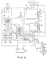
- a circuit arrangement of a control unit 18 including a microcomputer shown in Fig. 2 will be described hereunder.
- the microcomputer of the control unit 18 comprises, as shown in Fig. 2, a central processing unit (CPU) 18a, a read only memory (ROM) 18b, a random access memory (RAM) 18c and a I/O interface 18d which are connected through a bus line 18e with each other.
- CPU central processing unit
- ROM read only memory
- RAM random access memory
- the I/O interface 18d is provided with an input port to which are connected the crank angle sensor 8, the generator revolution number sensor 9 and the positive terminal of the battery 17 and a lux sensor 19 arranged to an upper portion of the electric automobile for detecting amount of dose of environmental ultraviolet ray or illumination such as of a light is further connected to the input port of the I/O interface 18d.
- the I/O interface 18d is also provided with an output port to which are connected an alarm means 20 such as a light emitting diode (LED), the primary side of the ignition circuit 14a constituting the ignition circuit 14, the rotary actuator 7 and the exciter coil of the first and second relays RE2 and RE4 constituting the generator controlling circuit 16.
- an alarm means 20 such as a light emitting diode (LED), the primary side of the ignition circuit 14a constituting the ignition circuit 14, the rotary actuator 7 and the exciter coil of the first and second relays RE2 and RE4 constituting the generator controlling circuit 16.
- LED light emitting diode
- Stationary data such as control program and various comparative reference values are stored in the ROM 18b.
- Data processing the output signals from the respective sensors are stored in the RAM 18c.
- the CPU 18a discriminates operation calculation of the rotary actuator 7, ignition timing setting and ignition cutting in dependency on the respective data.
- the control unit 18 comprises terminal voltage calculating means 21, indoor-outdoor discriminating means 22, generator revolution number calculating means 23, engine start-stop condition discriminating means 24, rotary actuator operation amount setting means 25, rotary actuator driving means 26, engine operation stopping means 27, and alarm driving means 28.
- the engine operation stopping means 27 includes ignition driving means 27a and first and second relay driving means 27b.
- the terminal voltage calculation means 21 calculates the terminal voltage VT of the battery 17 in accordance with the voltage of the battery 17.
- the indoor-outdoor discriminating means 22 compares an illumination L detected by the lux sensor 19 with a reference illumination Ls preliminarily set, and in case of L ⁇ Ls, it is discriminated that the automobile is now indoors, and in case of L ⁇ Ls, it is discriminated that the automobile is now outdoors.
- the generator revolution number calculating means 23 calculates the generator revolution number NGE in response to the output signal from the generator revolution number sensor 9.
- the engine start-stop operation condition discriminating means 24 compares the terminal voltage VT calculated by the terminal voltage calculating means 21 with a voltage lower limit value discriminating reference voltage VL (11V, for example) and a voltage upper limit value discriminating reference voltage VH. In case of VT ⁇ VL and L ⁇ Ls, it is discriminated that the engine start condition is established and in case of L ⁇ Ls or VT ⁇ VH, it is discriminated that the engine stop condition is established.
- the rotary actuator operation amount setting means 25 calculates, upon the condition of the engine start condition establishment of the engine start-stop operation discriminating means 24, the operation amount of the rotary actuator 7 from the deviation between the generator revolution number NGE calculated by the generator revolution number calculating means 23 and a preliminarily set generator revolution number NGEO.
- the operation amount may be set in accordance with map index operation. In a case where it is discriminated by the engine start-stop operation condition discriminating means 24 that the engine stop condition is established, the operation of the rotary actuator 7 stops.
- the rotary actuator driving means 26 operates to output an operation signal corresponding to the operation amount of the rotary actuator set by the rotary actuator operation amount setting means 25 to the rotary actuator 7.
- the rotary actuator 7 operates to open or close the throttle valve 7c so as to minutely control the engine speed and thereby amend or correct the speed variation in response to the engine load or the revolution number variation of the generator 2 due to slipping of the drive pulley 4, for example.
- the first and second relay driving means 27b operates to pass electric current to the exciter coils of the first and second relays RE2 and RE4 arranged in the generator control circuit 16 upon the discrimination of the engine start operation condition establishment of the engine start-stop operation condition discriminating means 24.
- the first and second relays RE2 and RE4 are made “ON” and discharge current from the battery 17 then flows, as shown by solid arrows in Fig. 1, in the diode D1 through the exciting coil of the change-over relay RE3, whereby the change-over relay RE3 is made "ON” and the normally open contact is closed to establish a starter circuit.
- the current flows in the armature 2a of the generator 2 and the field winding 2c without passing through the resistor R1.
- the generator 2 is operated to rotate in accordance with the current passing the field winding 2c and, hence, the engine 1 is driven by the driving of the generator 2 through the belt 6.
- the first and second relay driving means 27b operate to turn “OFF" the first and second relays RE2 and RE4 of the generator control circuit 16 to stop the charge or discharge of the battery with respect to the generator 2 upon the discrimination of the engine stop condition establishment of the engine start-stop operation condition discriminating means 24.
- the engine is now being operated (charged) and, hence, the step jumps to a step S104.
- the step is now stopped and, hence, the control advances to a step S102 to read the terminal voltage VT of the battery 17.
- a step S103 the terminal voltage VT read in the step S102 is compared with the preliminarily set voltage lower limit value discriminating reference voltage VL (11V, for example).
- VL the preliminarily set voltage lower limit value discriminating reference voltage
- VT ⁇ VL it is discriminated that the battery 17 is sufficiently charged, and the control jumps to a step S112.
- the control advances to the step S104, in which the output value L of the lux sensor 19 is read.
- the output value L read in the step S104 is compared with the preliminarily set indoor-outdoor discriminating reference illumination Ls.
- L ⁇ Ls it is discriminated to be outdoors and the control advances to a step S106 and in case of L ⁇ Ls, it is discriminated to be indoors and the control advances to a step S107.
- step S105 in case of the discrimination of L ⁇ Ls, i.e. when it is discriminated to be indoors, the control advances to the step S107, operating the engine is inhibited. Accordingly, an LED as one example of the alarm means 20 is lit to generate an alarm to inform an operator of the insufficient charge condition.
- the ignition unit is cut to stop the engine operation and further stop the operation of the rotary actuator 7.
- the first and second relays RE2 and RE4 are made "OFF".
- the engine condition discriminating flag is made clear (FLAG ⁇ ⁇ ) and the control is thereafter out of the routine.
- the engine is automatically stopped to thereby stop the charging operation of the battery 17. Accordingly, the charging operation is carried out only for outdoor driving of the electric automobile, so that the stable indoor conditions can be effectively maintained. In addition, the insufficient charged condition can be communicated to the indoor operator, so that the rapid stopping of the travelling of the electric automobile can be eliminated.
Landscapes
- Engineering & Computer Science (AREA)
- Transportation (AREA)
- Mechanical Engineering (AREA)
- Sustainable Development (AREA)
- Life Sciences & Earth Sciences (AREA)
- Sustainable Energy (AREA)
- Power Engineering (AREA)
- Combustion & Propulsion (AREA)
- Chemical & Material Sciences (AREA)
- Control Of Vehicle Engines Or Engines For Specific Uses (AREA)
- Hybrid Electric Vehicles (AREA)
- Combined Controls Of Internal Combustion Engines (AREA)
- Electric Propulsion And Braking For Vehicles (AREA)
- Output Control And Ontrol Of Special Type Engine (AREA)
Claims (5)
- Automatisches Ladesystem für ein Elektroautomobil, das mit einem Elektromotor (3) zum Antreiben der Räder des Automobils, einer Batterie (17), die in dem Automobil installiert ist, um elektrische Energie zu speichern und elektrische Energie zu dem Motor (3) zuzuführen, einem mit der Batterie (17) verbundenen Generator (2) zum Erzeugen von elektrischer Energie und zum Zuführen von elektrischer Energie zu der Batterie (17), und einem in dem Automobil installierten Motor (1) zum Antreiben des Generators versehen ist, wobei das Ladesystem eine Spannungsdetektionseinrichtung (21) zum Detektieren einer Klemmenspannung der Batterie umfaßt, und das gekennzeichnet ist durch;
eine Beleuchtungsdetektionseinrichtung (19) zum Detektieren der Stärke der Umgebungsbeleuchtung,
eine mit der Beleuchtungsdetektionseinrichtung (19) verbundene Diskriminiereinrichtung (22) zum Vergleichen der Stärke der Umgebungsbeleuchtung und eines vorbestimmten Beleuchtungswerts und zum Feststellen, ob sich das Fahrzeug im Freien befindet, eine Ermittlungseinrichtung (24), welche auf die Klemmenspannung und das detektierte Ergebnis der Diskriminiereinrichtung (22) reagiert, zum Feststellen einer Motorstart-Bedingung, um die Batterie aufzuladen, wenn die Klemmenspannung geringer als eine vorbestimmte untere Schwellenspannung ist und das Fahrzeug sich im Freien befindet, und
eine Einrichtung zum Starten und Abstellen (27), um den Motor in Abhängigkeit von der Motorstart-Bedingung zu starten und um den Betrieb des Motors in Übereinstimmung mit einem Detektionsergebnis der Ermittlungseinrichtung (24) zu beenden. - Automatisches Ladesystem nach Anspruch 1, bei dem die Ermittlungseinrichtung (24) die Klemmenspannung und eine vorbestimmte obere Schwellenspannung vergleicht, um eine Bedingung für das Abstellen des Motors festzustellen, wenn die Klemmenspannung größer als die vorbestimmte obere Schwellenspannung ist.
- Automatisches Ladesystem nach Anspruch 1 oder 2, bei dem die Ermittlungseinrichtung (24) eine Bedingung für das Abstellen des Motors feststellt, wenn sich das Fahrzeug nicht im Freien befindet.
- Automatisches Ladesystem nach einem der Ansprüche 1 bis 3, bei dem die Diskriminiereinrichtung (22) feststellt, daß sich das Fahrzeug im Freien befindet, wenn die Stärke der Umgebungsbeleuchtung größer als der vorbestimmte Wert ist.
- Automatisches Ladesystem nach Anspruch 1, bei dem die Diskriminiereinrichtung (22) feststellt, daß sich das Fahrzeug nicht im Freien befindet, wenn die Stärke der Umgebungsbeleuchtung kleiner als der vorbestimmte Wert ist.
Applications Claiming Priority (2)
| Application Number | Priority Date | Filing Date | Title |
|---|---|---|---|
| JP279108/89 | 1989-10-25 | ||
| JP27910889A JP2790256B2 (ja) | 1989-10-25 | 1989-10-25 | 電気自動車の自動充電装置 |
Publications (2)
| Publication Number | Publication Date |
|---|---|
| EP0424906A1 EP0424906A1 (de) | 1991-05-02 |
| EP0424906B1 true EP0424906B1 (de) | 1994-06-29 |
Family
ID=17606529
Family Applications (1)
| Application Number | Title | Priority Date | Filing Date |
|---|---|---|---|
| EP90120402A Expired - Lifetime EP0424906B1 (de) | 1989-10-25 | 1990-10-24 | Automatisches Ladesystem für elektrische Fahrzeuge |
Country Status (4)
| Country | Link |
|---|---|
| US (1) | US5150034A (de) |
| EP (1) | EP0424906B1 (de) |
| JP (1) | JP2790256B2 (de) |
| DE (1) | DE69010302T2 (de) |
Families Citing this family (24)
| Publication number | Priority date | Publication date | Assignee | Title |
|---|---|---|---|---|
| US5202617A (en) * | 1991-10-15 | 1993-04-13 | Norvik Technologies Inc. | Charging station for electric vehicles |
| JP3000804B2 (ja) * | 1992-10-21 | 2000-01-17 | 日産自動車株式会社 | ハイブリッド型電気自動車 |
| DE19828560C2 (de) * | 1998-06-26 | 2000-05-25 | Fraunhofer Ges Forschung | Vorrichtung zum Überprüfen von autonomen Solaranlagen |
| RU2222098C2 (ru) * | 2002-04-09 | 2004-01-20 | Открытое акционерное общество "АВТОВАЗ" | Комплектный тяговый электропривод |
| RU2222096C2 (ru) * | 2002-04-09 | 2004-01-20 | Открытое акционерное общество "АВТОВАЗ" | Комплектный тяговый электропривод постоянного тока |
| US7293621B2 (en) * | 2002-04-10 | 2007-11-13 | Charge-O-Matic Energy Recovery Devices, Llc | Vehicle drive system with energy recovery system and vehicle mounting same |
| US20060213703A1 (en) * | 2002-04-10 | 2006-09-28 | Long Thomas W | Vehicle drive system with energy recovery system and vehicle mounting same |
| JP2005083195A (ja) * | 2003-09-04 | 2005-03-31 | Honda Motor Co Ltd | 電源装置 |
| JP4461824B2 (ja) * | 2004-02-13 | 2010-05-12 | トヨタ自動車株式会社 | 自動車、自動車の制御方法、制御方法をコンピュータに実行させるためのプログラムを記録したコンピュータ読取可能な記録媒体 |
| US7107956B2 (en) * | 2004-07-30 | 2006-09-19 | Ford Global Technologies, Llc | Vehicle and method for controlling engine start in a vehicle |
| US20060030450A1 (en) * | 2004-08-09 | 2006-02-09 | Kyle Ronald L | Hybrid vehicle formed by converting a conventional IC engine powered vehicle and method of such conversion |
| US20100044129A1 (en) * | 2004-08-09 | 2010-02-25 | Hybrid Electric Conversion Co., Llc | Hybrid vehicle formed by converting a conventional ic engine powered vehicle and method of such conversion |
| JP4890953B2 (ja) | 2006-06-13 | 2012-03-07 | オリンパス株式会社 | カプセル内視鏡システム |
| JP2011084224A (ja) * | 2009-10-18 | 2011-04-28 | Masahide Tanaka | モータ駆動可能な車両 |
| US8841881B2 (en) | 2010-06-02 | 2014-09-23 | Bryan Marc Failing | Energy transfer with vehicles |
| US20130110376A1 (en) * | 2011-11-01 | 2013-05-02 | Ford Global Technologies, Llc | Method and system for engine control |
| US8972152B2 (en) * | 2011-11-01 | 2015-03-03 | Ford Global Technologies, Llc | Method and system for inhibiting engine idle stop based on operating conditions |
| JP5716693B2 (ja) * | 2012-02-28 | 2015-05-13 | トヨタ自動車株式会社 | ハイブリッド車両 |
| JP6152299B2 (ja) * | 2013-05-16 | 2017-06-21 | 株式会社Subaru | 密閉空間検出装置および自動車 |
| JP5920329B2 (ja) * | 2013-12-24 | 2016-05-18 | トヨタ自動車株式会社 | 車両 |
| US10569638B2 (en) * | 2014-06-25 | 2020-02-25 | Heinz Welschoff | All electric vehicle without plug-in requirement |
| US10913443B2 (en) * | 2017-05-22 | 2021-02-09 | Ford Global Technologies, Llc | Powertrain control based on auxiliary battery characteristics |
| JP2019034567A (ja) * | 2017-08-10 | 2019-03-07 | トヨタ自動車株式会社 | ハイブリッド車両及びハイブリッド車両の制御方法 |
| US11598259B2 (en) * | 2019-08-29 | 2023-03-07 | Achates Power, Inc. | Hybrid drive system with an opposed-piston, internal combustion engine |
Family Cites Families (12)
| Publication number | Priority date | Publication date | Assignee | Title |
|---|---|---|---|---|
| US3792327A (en) * | 1972-10-05 | 1974-02-12 | L Waldorf | Hybrid electrical vehicle drive |
| US4021677A (en) * | 1975-03-03 | 1977-05-03 | Petro-Electric Motors, Ltd. | Hybrid power system |
| US4042056A (en) * | 1975-11-21 | 1977-08-16 | Automobile Corporation Of America | Hybrid powered automobile |
| US4090577A (en) * | 1977-04-18 | 1978-05-23 | Moore Wallace H | Solar celled hybrid vehicle |
| DE2945303A1 (de) * | 1979-11-09 | 1981-05-21 | Volkswagenwerk Ag | Hybridantrieb fuer ein fahrzeug |
| EP0073861A1 (de) * | 1981-09-04 | 1983-03-16 | Alexander Mencher Corporation | Hybridantriebsvorrichtung und -methode |
| US4477764A (en) * | 1982-07-15 | 1984-10-16 | Pollard Earsel W | Energy generating and storage system for electric vehicle or the like |
| US4592436A (en) * | 1982-08-19 | 1986-06-03 | Tomei Edmardo J | Solar powered vehicle |
| US4593779A (en) * | 1982-12-21 | 1986-06-10 | Still Gmbh | Combination internal combustion and electrical drive vehicles |
| DE3526458A1 (de) * | 1985-07-24 | 1987-01-29 | Grundig Emv | Einrichtung zur optischen truebungsmessung von gasen |
| US4629968A (en) * | 1985-08-23 | 1986-12-16 | General Motors Corporation | Alternator load control system |
| US4888702A (en) * | 1987-08-20 | 1989-12-19 | Integrated Power Corporation | Photovoltaic system controller |
-
1989
- 1989-10-25 JP JP27910889A patent/JP2790256B2/ja not_active Expired - Fee Related
-
1990
- 1990-10-24 DE DE69010302T patent/DE69010302T2/de not_active Expired - Fee Related
- 1990-10-24 EP EP90120402A patent/EP0424906B1/de not_active Expired - Lifetime
- 1990-10-24 US US07/602,146 patent/US5150034A/en not_active Expired - Lifetime
Also Published As
| Publication number | Publication date |
|---|---|
| DE69010302D1 (de) | 1994-08-04 |
| JP2790256B2 (ja) | 1998-08-27 |
| JPH03143201A (ja) | 1991-06-18 |
| DE69010302T2 (de) | 1995-02-09 |
| EP0424906A1 (de) | 1991-05-02 |
| US5150034A (en) | 1992-09-22 |
Similar Documents
| Publication | Publication Date | Title |
|---|---|---|
| US5150034A (en) | Automatically charging system for electric automobile | |
| EP0428130B1 (de) | Batterieladesystem für Motorgenerator | |
| US5664635A (en) | Control system for inhibiting unintended use of hybrid electric vehicle | |
| CA2022996C (en) | Motor vehicle power supply device | |
| US6659213B2 (en) | Control device for hybrid vehicle | |
| EP1036696B1 (de) | System zur Regelung des Verbrennungsmotors in einem Hybridauto | |
| US6435294B1 (en) | Control device for hybrid vehicle | |
| US10328816B2 (en) | Hybrid vehicle, cooperation system, and control method for hybrid vehicle | |
| US5352971A (en) | Electronic control apparatus for a vehicle | |
| US6469403B2 (en) | Control apparatus for hybrid vehicle | |
| EP0429058B1 (de) | Elektrisches Fahrzeug | |
| FR2829308A1 (fr) | Systeme d'alimentation electrique pour demarreur de moteur | |
| US4684917A (en) | Low oil warning circuit | |
| US4323837A (en) | Power supply circuit for automotive vehicles | |
| EP0845383B1 (de) | Regler für eine kraftfahrzeug eigene batterie | |
| JPH0746709A (ja) | パラレルハイブリッド車のバッテリ充放電制御装置 | |
| EP0424868B1 (de) | Antriebssystem für einen Fahrzeugmotor | |
| JP2002155775A (ja) | エンジン自動制御装置 | |
| JPH104601A (ja) | 車載電池の表示装置 | |
| JPH1014004A (ja) | 車載電池の制御装置 | |
| KR101020896B1 (ko) | 차량용 배터리 상태 제어장치와 제어 방법 | |
| JP2929475B2 (ja) | ハイブリッド車のバッテリ充電制御装置 | |
| JPH06225405A (ja) | 電気自動車用エンジン駆動発電機の制御装置 | |
| JP2002118978A (ja) | 自動車用電源システム | |
| JP3913315B2 (ja) | 発電制御装置 |
Legal Events
| Date | Code | Title | Description |
|---|---|---|---|
| PUAI | Public reference made under article 153(3) epc to a published international application that has entered the european phase |
Free format text: ORIGINAL CODE: 0009012 |
|
| 17P | Request for examination filed |
Effective date: 19901024 |
|
| AK | Designated contracting states |
Kind code of ref document: A1 Designated state(s): DE FR GB |
|
| 17Q | First examination report despatched |
Effective date: 19921023 |
|
| GRAA | (expected) grant |
Free format text: ORIGINAL CODE: 0009210 |
|
| AK | Designated contracting states |
Kind code of ref document: B1 Designated state(s): DE FR GB |
|
| REF | Corresponds to: |
Ref document number: 69010302 Country of ref document: DE Date of ref document: 19940804 |
|
| ET | Fr: translation filed | ||
| PLBE | No opposition filed within time limit |
Free format text: ORIGINAL CODE: 0009261 |
|
| STAA | Information on the status of an ep patent application or granted ep patent |
Free format text: STATUS: NO OPPOSITION FILED WITHIN TIME LIMIT |
|
| 26N | No opposition filed | ||
| PGFP | Annual fee paid to national office [announced via postgrant information from national office to epo] |
Ref country code: GB Payment date: 19971015 Year of fee payment: 8 |
|
| PG25 | Lapsed in a contracting state [announced via postgrant information from national office to epo] |
Ref country code: GB Free format text: LAPSE BECAUSE OF NON-PAYMENT OF DUE FEES Effective date: 19981024 |
|
| REG | Reference to a national code |
Ref country code: FR Ref legal event code: D6 |
|
| GBPC | Gb: european patent ceased through non-payment of renewal fee |
Effective date: 19981024 |
|
| PGFP | Annual fee paid to national office [announced via postgrant information from national office to epo] |
Ref country code: FR Payment date: 20001010 Year of fee payment: 11 |
|
| PGFP | Annual fee paid to national office [announced via postgrant information from national office to epo] |
Ref country code: DE Payment date: 20001016 Year of fee payment: 11 |
|
| PG25 | Lapsed in a contracting state [announced via postgrant information from national office to epo] |
Ref country code: FR Free format text: LAPSE BECAUSE OF NON-PAYMENT OF DUE FEES Effective date: 20020628 |
|
| PG25 | Lapsed in a contracting state [announced via postgrant information from national office to epo] |
Ref country code: DE Free format text: LAPSE BECAUSE OF NON-PAYMENT OF DUE FEES Effective date: 20020702 |
|
| REG | Reference to a national code |
Ref country code: FR Ref legal event code: ST |