EP0424927A2 - Cassette de métal en feuilles pour le rangement d'outils - Google Patents
Cassette de métal en feuilles pour le rangement d'outils Download PDFInfo
- Publication number
- EP0424927A2 EP0424927A2 EP90120436A EP90120436A EP0424927A2 EP 0424927 A2 EP0424927 A2 EP 0424927A2 EP 90120436 A EP90120436 A EP 90120436A EP 90120436 A EP90120436 A EP 90120436A EP 0424927 A2 EP0424927 A2 EP 0424927A2
- Authority
- EP
- European Patent Office
- Prior art keywords
- cassette
- insert
- tools
- cassette according
- cover
- Prior art date
- Legal status (The legal status is an assumption and is not a legal conclusion. Google has not performed a legal analysis and makes no representation as to the accuracy of the status listed.)
- Granted
Links
- 239000002184 metal Substances 0.000 title claims abstract description 14
- 238000005192 partition Methods 0.000 claims description 10
- 210000003128 head Anatomy 0.000 claims description 5
- 210000002105 tongue Anatomy 0.000 claims description 4
- 230000001154 acute effect Effects 0.000 claims description 3
- 230000005484 gravity Effects 0.000 description 1
- 238000003780 insertion Methods 0.000 description 1
- 230000037431 insertion Effects 0.000 description 1
- 230000002093 peripheral effect Effects 0.000 description 1
- 230000007704 transition Effects 0.000 description 1
Images



Classifications
-
- B—PERFORMING OPERATIONS; TRANSPORTING
- B25—HAND TOOLS; PORTABLE POWER-DRIVEN TOOLS; MANIPULATORS
- B25H—WORKSHOP EQUIPMENT, e.g. FOR MARKING-OUT WORK; STORAGE MEANS FOR WORKSHOPS
- B25H3/00—Storage means or arrangements for workshops facilitating access to, or handling of, work tools or instruments
- B25H3/003—Holders for drill bits or the like
Definitions
- the invention relates to a sheet metal cassette for receiving a hand drive tool, for. B. a ratchet, and associated tools such as bits, bit rods, socket wrench inserts and the like., With an insert in which the tools are approximately parallel between the cassette bottom and lid when the cassette is closed.
- Such sheet metal cassettes are known in numerous embodiments.
- the tools are inserted into inserts with matching receiving troughs, which in turn sit in the box bottom.
- Tool boxes are also known in which corresponding tool holders are also arranged on the underside of the cover. The removal of the tools is still relatively cumbersome with these boxes.
- the invention has for its object to provide a generic sheet metal cassette in such a way that the tools are particularly accessible and clearly arranged.
- the insert is designed as a flat tool stand which is pivotally mounted near the rear wall of the cassette about an axis parallel to the cover pivot axis and is articulated on the cassette cover via articulated or flexible tension members in such a way that the stand - when folded up of the lid can be swiveled into an upright position.
- the insert consists of one or two identical, superimposed, narrow perforated strips extending over the length of the cassette, a main wall perpendicular thereto with lateral bearing eyes for pivotable mounting on bearing axles held by the cassette side walls and one or more Skirting boards to support the tools exist.
- the tension members can consist of approximately U-shaped, resilient brackets, the bottom legs of which are articulated to webs pressed out of the cover and the U-side legs end in eyelets which are snapped out in pairs on opposite tongues punched out of one of the perforated strips.
- a receiving space for the manual drive tool which is delimited by a longitudinal dividing wall attached to the box bottom, can be arranged directly behind the cassette front wall, the insert can only occupy the rear area of the box room and an intermediate space between the outer perforated strip and the longitudinal dividing wall for receiving those that protrude from the insert Leave the tool ends.
- the longitudinal partition wall can also be provided with at least one interruption for receiving long tools reaching up to the front wall of the cassette.
- the insert is provided with several vertically offset baseboards, the distances of which - with the cassette closed - from the longitudinal partition or the front wall of the cassette are only approximately less than the length of the tools to be accommodated, so that So the tools are also bordered in the axial direction.
- the insert is about half as flat as the cassette, that the insert is articulated to the upper region of the cassette side walls, that a stop is arranged on the cassette bottom to secure the horizontal position of the tools when the cassette is closed and that the cassette cover can be pivoted by approximately 135 ° into an open position, which is secured by striking the insert against the cassette rear wall.
- a longitudinal recess is formed in the main wall of the insert, on the lower longitudinal edge of which there are arranged a series of hooks for inserting socket wrench inserts which are received by the longitudinal recess only over part of their diameter.
- an essentially U-shaped retaining strip is arranged on the main wall, which is connected to the free longitudinal edge of one leg in an articulated manner below the longitudinal recess, the back the retaining bar is at least as wide as the longitudinal trough.
- the leg connected to the main wall can have two hooks angled to the outside of the retaining bar, which are hooked into slot recesses in the main wall.
- the leg of the retaining bar facing away from the main wall with its back includes an angle of approximately 120 °.
- a receptacle for the additional tool or tools is connected to it, and this pivoting range is so limited when the cassette cover is open that the longitudinal axis of the tools arranged therein is one with the bottom of the lower box includes an acute angle and which has an upper and a lower receiving recess for each of the tools, which are designed so that the tools can in turn pivot in a plane perpendicular to the pivot axis of the insert.
- the tools accommodated therein can automatically pivot away from the tools arranged in use due to the force of gravity when the cassette cover is opened, so that the tools can be gripped more easily at their upper ends because of their then mutually enlarged distance.
- the limitation of the swivel range of the receiving part ensures that the objects are not placed in a vertical orientation and can therefore tip against the insert.
- the receiving part can be designed as an essentially U-shaped profile part and can be connected to the insert with the end faces of the two U-profile legs.
- the upper receiving recess is expediently designed as an elongated hole extending in a plane perpendicular to the longitudinal axis of the insert, whereby a pivoting movement of the tools about an axis parallel to the axis of the insert is possible.
- the lower receiving recess is designed as a bead-like depression.
- the bead-like recess can advantageously be formed by a free cut in the lower leg of the receiving part, the free cutting comprising a support adapted to the shape of the contour of the respective tool and two tabs projecting diametrically from the support, the end of the tabs facing away from the support being connected to the receiving part and the end connected to the support is bent out of the plane of the lower leg.
- the bead-like depression forms both the base plate and the lower radial guide for the object or the tool.
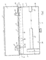
- the sheet metal cassette consists of a lower box 1 with front wall 2, side walls 3, 4 and rear wall 5, from a cover 6 with a pulled-down, peripheral edge 7 and an insert 8 which in the upper, rear corner regions of the side walls 3, 4 about an axis 9 is pivotally mounted.
- the insert 8 consists of two identical, narrow, overlapping perforated strips 10, 11 extending over the length of the cassette, a main or front wall 12 perpendicular thereto and two height-adjustable baseboards 13, 14. Side parts 15, 16 protrude from the main wall 12 at right angles from. in which bearing eyes 17 are provided for the bearing axis 9 formed from rivets.
- the perforated strips 10, 11 are provided with differently sized and differently shaped holes 18, which are only indicated symbolically in FIG. 2.
- the insert 8 is articulated to the cover 6 via tension members 19, 20.
- the tension members consist of approximately U-shaped, resilient brackets, the base legs 21 of which are articulated on webs 22 pressed out of the cover 6 and the U side legs 23 end in eyelets 24, which are located in pairs opposite one another from the outer or upper perforated strip 10 punched-out tongues 25 are snapped.
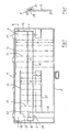
- a receiving space 28 delimited by a longitudinal partition wall 27 attached to the box bottom 26, for a hand drive tool 29, indicated by dashed lines, in the form of a ratchet.
- the insert 8 only occupies the rear area of the box interior and leaves an intermediate space Z between the outer perforated strip 10 and the longitudinal partition wall 27.
- the longitudinal partition wall 27 is provided with interruptions 30, 31.
- Tools 32, 33, 34 of different lengths are inserted, which protrude a bit from the insert 8, so that they can be gripped comfortably.
- the tools are only indicated with dash-dotted lines, a distance A for short tools 33 being provided between the skirting board 13 and the partition wall 27 and a distance B for long tools 34 being provided between the skirting board 14 and the front wall 2 of the box, that these tools are framed on the front.
- Tools 32 are shown on the longitudinal ends of the insert, each of which rests on the upper perforated strip 10 with an annular shoulder 35.
- the insert 8 is about half as flat as the cassette.
- a stop 36 in the form of an L-angle for securing the horizontal position of the tools 32, 33, 34 is attached to the cassette bottom 26 when the cassette is closed.
- the articulation of the cover 6 consists of rolled-in tabs 37, which act as hinge sleeves and are pressed out of the rear wall 5 of the box and enclose tongues 38 stamped out from the edge 7 of the lid.
- the lid 6 can be opened by approximately 135 ° and secured in this position by striking the side parts 15, 16 of the insert 8 against the rear wall 5 of the box.
- the pivot axis 39 of the cover 6 is offset next to the pivot axis 9 of the insert 8.
- a longitudinal recess 42 is formed in the main wall 40 of the insert 41, on the lower longitudinal edge of which a number of hooks 43 are arranged for the insertion of socket wrench inserts 44, 45, which only have a part of their diameter the longitudinal trough 42 are added.
- a stop bar 46 is arranged on the cassette base 26, on which the socket wrench inserts 44, 45 hit when the insert 41 is pivoted down and which hold the socket wrench inserts axially between the hook base 47 on the one hand and either the top wall 48 of the longitudinal recess 42 or the stop bar 46 itself.
- the stop bar 46 is provided with semicircular recesses 49 for receiving the heads of the socket wrench inserts 44, 45.
- the recesses 49 are graded according to the different thickness of the heads, and especially in the case of the socket wrench inserts 44, in which the head is smaller in diameter than the foot end, the stop bar 46 serves as an axial border or an axial counter-holder in the closed position. In the socket wrench inserts 45 with a thicker head, the stop bar 46 holds the socket wrench inserts in the closed position in the longitudinal recess 42, so that their Upper wall 48 causes the axial counter bracket.
- an essentially U-shaped retaining strip 50 is arranged on the main wall 40 and is connected in an articulated manner below the longitudinal recess 42 with the free longitudinal edge of one leg 51.
- the back of the retaining bar 50 is at least as wide as the longitudinal trough 42, so that the largest socket wrench inserts are overlapped by the retaining bar 50.
- the leg 51 connected to the main wall 40 has two hooks which are angled by 180 ° to the outside of the retaining strip 50 and are hooked into slot recesses in the main wall 40.
- the leg 52 of the retaining strip 50 facing away from the main wall 40 encloses an angle of approximately 120 ° with its back.
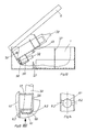
- a receptacle part 56 which is fixedly connected to the cassette cover 6 and faces away from the cassette cover 6, for further objects or tools 32, 33, 34.
- this receiving part 56 is only pivoted open to the extent that the longitudinal axis of the tools 32, 33, 34 arranged therein with the bottom of the lower box 1 encloses an acute angle, as can be seen from FIG. 10.
- the receiving part 56 has an upper and a lower receiving recess 57, 58 for each of the tools 32, 33, 34, the receiving recesses 57, 58 being designed such that the tools 32, 33, 34 are in relation to the pivot axis 59 of the pivot insert 8 vertical plane in turn can perform a pivoting movement.
- the receiving part 56 is designed as an essentially U-shaped profile part and is connected to the end faces of the two U-profile legs on the swivel insert 8.
- the upper receiving recess 57 is formed as an elongated hole extending in the plane perpendicular to the pivot axis 59 of the pivot insert 8.
- the lower receiving recess 58 is designed as a bead-like depression.
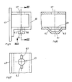
- the lower receiving recess 58 forms both a base plate 8.1 for the axial movement of the tools 32, 33, 34 and a radial guide through the boundary of the bead-like depression.
- the bead-like depression is formed by a free cut in the lower leg of the receiving part 56.
- the free cut includes the base plate 8.1 adapted to the shape of the respective tool 32, 33, 34 and two tabs 82 protruding diametrically from the base plate 8.1.
- the end of the tabs 8.2 facing away from the base plate 8.1 is connected to the receiving part 56, while that with the base plate 8.1 connected end is bent out of the plane of the lower leg.
Landscapes
- Engineering & Computer Science (AREA)
- Mechanical Engineering (AREA)
- Packaging Of Annular Or Rod-Shaped Articles, Wearing Apparel, Cassettes, Or The Like (AREA)
Applications Claiming Priority (6)
| Application Number | Priority Date | Filing Date | Title |
|---|---|---|---|
| DE8912755U | 1989-10-27 | ||
| DE8912755 | 1989-10-27 | ||
| DE8914050U | 1989-11-29 | ||
| DE8914050U DE8914050U1 (de) | 1989-10-27 | 1989-11-29 | Blechkassette zur Aufnahme von Werkzeugen |
| DE9002042U DE9002042U1 (de) | 1990-02-21 | 1990-02-21 | Kassette zur Aufbewahrung von Gegenständen, insbesondere auch von länglichen Werkzeugen |
| DE9002042U | 1990-02-21 |
Publications (3)
| Publication Number | Publication Date |
|---|---|
| EP0424927A2 true EP0424927A2 (fr) | 1991-05-02 |
| EP0424927A3 EP0424927A3 (en) | 1991-07-03 |
| EP0424927B1 EP0424927B1 (fr) | 1994-03-02 |
Family
ID=27208105
Family Applications (1)
| Application Number | Title | Priority Date | Filing Date |
|---|---|---|---|
| EP90120436A Expired - Lifetime EP0424927B1 (fr) | 1989-10-27 | 1990-10-25 | Cassette de métal en feuilles pour le rangement d'outils |
Country Status (2)
| Country | Link |
|---|---|
| EP (1) | EP0424927B1 (fr) |
| DE (1) | DE59004762D1 (fr) |
Cited By (3)
| Publication number | Priority date | Publication date | Assignee | Title |
|---|---|---|---|---|
| US5570784A (en) * | 1992-12-24 | 1996-11-05 | Allied Wholesale, Inc. | Tool organizer and deployment apparatus |
| GB2311279A (en) * | 1996-03-22 | 1997-09-24 | Knoblauch Georg Fa | Box for the storage of elongate articles |
| EP1716057A4 (fr) * | 2004-02-18 | 2010-05-05 | Black & Decker Inc | Contenant de stockage |
Family Cites Families (13)
| Publication number | Priority date | Publication date | Assignee | Title |
|---|---|---|---|---|
| US3096877A (en) * | 1961-10-02 | 1963-07-09 | Thorsen Mfg Company | Packages and methods of packaging |
| US3878939A (en) * | 1972-04-17 | 1975-04-22 | Charles L Wilcox | Folding tool case |
| AT336522B (de) * | 1974-08-30 | 1977-05-10 | Reischl Max Metallwaren | Zusammenklappbarer werkzeughalter |
| DE7443342U (de) * | 1974-12-28 | 1980-10-30 | Knoblauch Werkzeug | Kassette zur Aufbewahrung laenglicher Gegenstaende insbesondere Werkzeuge |
| GB1551250A (en) * | 1975-06-17 | 1979-08-30 | Parkes & Sons Ltd Benjamin | Boxes for drills or other articles of elongated shape |
| DE8135902U1 (de) * | 1981-12-10 | 1982-03-11 | Giess & Quanz Gmbh, 5630 Remscheid | Gewindeschneidwerkzeug-Transporteinheit mit Gewindebohrsicherung |
| GB2135279B (en) * | 1983-02-22 | 1986-04-30 | Knoblauch Georg Gmbh | Case for storing elongate articles in particular tools |
| DE8509796U1 (de) * | 1985-04-02 | 1985-05-15 | Fa. Georg Knoblauch, 7928 Giengen | Kassette zur Aufbewahrung von Gegenständen, insbesondere von Werkzeugen |
| DE8512275U1 (de) * | 1985-04-25 | 1985-06-05 | Gisbert Brinkschulte Gmbh & Co Kg, 2800 Bremen | Kassette zur Aufbewahrung länglicher Gegenstände |
| DE8514919U1 (de) * | 1985-05-21 | 1985-06-27 | Fa. Georg Knoblauch, 7928 Giengen | Kassette zur Aufbewahrung länglicher Gegenstände, insbesondere Werkzeuge |
| GB8727935D0 (en) * | 1987-11-30 | 1988-01-06 | Decarie P G | Socket wrench tool box |
| DE8812791U1 (de) * | 1988-10-12 | 1988-11-24 | Völkel KG, 5630 Remscheid | Kassette zur Aufbewahrung länglicher Gegenstände |
| DE3837829C1 (fr) * | 1988-11-08 | 1989-10-05 | Fa. Georg Knoblauch, 7928 Giengen, De |
-
1990
- 1990-10-25 DE DE90120436T patent/DE59004762D1/de not_active Expired - Fee Related
- 1990-10-25 EP EP90120436A patent/EP0424927B1/fr not_active Expired - Lifetime
Cited By (4)
| Publication number | Priority date | Publication date | Assignee | Title |
|---|---|---|---|---|
| US5570784A (en) * | 1992-12-24 | 1996-11-05 | Allied Wholesale, Inc. | Tool organizer and deployment apparatus |
| GB2311279A (en) * | 1996-03-22 | 1997-09-24 | Knoblauch Georg Fa | Box for the storage of elongate articles |
| GB2311279B (en) * | 1996-03-22 | 1999-10-06 | Knoblauch Georg Fa | Box for the storage of elongate articles |
| EP1716057A4 (fr) * | 2004-02-18 | 2010-05-05 | Black & Decker Inc | Contenant de stockage |
Also Published As
| Publication number | Publication date |
|---|---|
| DE59004762D1 (de) | 1994-04-07 |
| EP0424927B1 (fr) | 1994-03-02 |
| EP0424927A3 (en) | 1991-07-03 |
Similar Documents
| Publication | Publication Date | Title |
|---|---|---|
| EP0476343B1 (fr) | Boîte pour jeux de tournevis | |
| DE1805523C3 (de) | Trageinrichtung für Fachboden od.dgl. mit einem Tragarm | |
| EP0158912B1 (fr) | Dispositif de support pour outils de dentiste | |
| DE20218574U1 (de) | Trägersystem für Regalelemente | |
| DE3040182A1 (de) | Winkelanpassstueck fuer wasserwaagen | |
| EP1187093A1 (fr) | Support pour instrument de musique | |
| EP0424927A2 (fr) | Cassette de métal en feuilles pour le rangement d'outils | |
| DE69006847T2 (de) | Papierspender für Badezimmer (breite Rolle). | |
| DE2707585A1 (de) | Geraetehaus | |
| DE8512275U1 (de) | Kassette zur Aufbewahrung länglicher Gegenstände | |
| DE3601230C2 (fr) | ||
| DE9014279U1 (de) | Blechkassette zur Aufnahme von Werkzeugen | |
| DE2721348C2 (de) | Halterung für WC-Desodorantien | |
| DE102018118772B4 (de) | Stecknusshalterahmenbaugruppe | |
| DE3200283C2 (de) | Zusammenlegbarer Grill | |
| EP0306555B1 (fr) | Pot particulierement pour abreuver des animaux | |
| DE3441050C2 (fr) | ||
| DE9417660U1 (de) | Instrumententräger | |
| EP4470435B1 (fr) | Dispositif de maintien d'au moins un récipient pour un produit d'hygiène personnelle liquide | |
| DE3524599C2 (fr) | ||
| DE2209532A1 (de) | Stange zum einfuehren von vorhangtraegern | |
| DE3129096A1 (de) | Vorrichtung zum dosierten abgeben von fluessigen oder pastenartigen stoffen | |
| DE1154245B (de) | Halter zum Befestigen von Tragschienen fuer Gardinen, Vorhaenge u. dgl. | |
| DE4101073C2 (de) | Einhängebeschlag für Körbe, Platten o. dgl. | |
| DE29603305U1 (de) | Haltevorrichtung für die Wandhalterung von Küchenutensilien |
Legal Events
| Date | Code | Title | Description |
|---|---|---|---|
| PUAI | Public reference made under article 153(3) epc to a published international application that has entered the european phase |
Free format text: ORIGINAL CODE: 0009012 |
|
| AK | Designated contracting states |
Kind code of ref document: A2 Designated state(s): BE DE FR GB IT LU NL |
|
| PUAL | Search report despatched |
Free format text: ORIGINAL CODE: 0009013 |
|
| AK | Designated contracting states |
Kind code of ref document: A3 Designated state(s): BE DE FR GB IT LU NL |
|
| 17P | Request for examination filed |
Effective date: 19910913 |
|
| 17Q | First examination report despatched |
Effective date: 19921130 |
|
| GRAA | (expected) grant |
Free format text: ORIGINAL CODE: 0009210 |
|
| AK | Designated contracting states |
Kind code of ref document: B1 Designated state(s): BE DE FR GB IT LU NL |
|
| REF | Corresponds to: |
Ref document number: 59004762 Country of ref document: DE Date of ref document: 19940407 |
|
| ET | Fr: translation filed | ||
| ITF | It: translation for a ep patent filed | ||
| GBT | Gb: translation of ep patent filed (gb section 77(6)(a)/1977) |
Effective date: 19940520 |
|
| PGFP | Annual fee paid to national office [announced via postgrant information from national office to epo] |
Ref country code: FR Payment date: 19941006 Year of fee payment: 5 |
|
| PGFP | Annual fee paid to national office [announced via postgrant information from national office to epo] |
Ref country code: GB Payment date: 19941017 Year of fee payment: 5 |
|
| PG25 | Lapsed in a contracting state [announced via postgrant information from national office to epo] |
Ref country code: LU Free format text: LAPSE BECAUSE OF NON-PAYMENT OF DUE FEES Effective date: 19941031 Ref country code: BE Effective date: 19941031 |
|
| PLBE | No opposition filed within time limit |
Free format text: ORIGINAL CODE: 0009261 |
|
| STAA | Information on the status of an ep patent application or granted ep patent |
Free format text: STATUS: NO OPPOSITION FILED WITHIN TIME LIMIT |
|
| 26N | No opposition filed | ||
| BERE | Be: lapsed |
Owner name: FIRMA GEORG KNOBLAUCH Effective date: 19941031 |
|
| PG25 | Lapsed in a contracting state [announced via postgrant information from national office to epo] |
Ref country code: NL Effective date: 19950501 |
|
| NLV4 | Nl: lapsed or anulled due to non-payment of the annual fee | ||
| PG25 | Lapsed in a contracting state [announced via postgrant information from national office to epo] |
Ref country code: GB Effective date: 19951025 |
|
| GBPC | Gb: european patent ceased through non-payment of renewal fee |
Effective date: 19951025 |
|
| PG25 | Lapsed in a contracting state [announced via postgrant information from national office to epo] |
Ref country code: FR Effective date: 19960628 |
|
| REG | Reference to a national code |
Ref country code: FR Ref legal event code: ST |
|
| PGFP | Annual fee paid to national office [announced via postgrant information from national office to epo] |
Ref country code: DE Payment date: 19961214 Year of fee payment: 7 |
|
| PG25 | Lapsed in a contracting state [announced via postgrant information from national office to epo] |
Ref country code: DE Free format text: LAPSE BECAUSE OF NON-PAYMENT OF DUE FEES Effective date: 19980701 |
|
| PG25 | Lapsed in a contracting state [announced via postgrant information from national office to epo] |
Ref country code: IT Free format text: LAPSE BECAUSE OF NON-PAYMENT OF DUE FEES;WARNING: LAPSES OF ITALIAN PATENTS WITH EFFECTIVE DATE BEFORE 2007 MAY HAVE OCCURRED AT ANY TIME BEFORE 2007. THE CORRECT EFFECTIVE DATE MAY BE DIFFERENT FROM THE ONE RECORDED. Effective date: 20051025 |