EP0425190B1 - Conteneur-citerne - Google Patents
Conteneur-citerne Download PDFInfo
- Publication number
- EP0425190B1 EP0425190B1 EP90311400A EP90311400A EP0425190B1 EP 0425190 B1 EP0425190 B1 EP 0425190B1 EP 90311400 A EP90311400 A EP 90311400A EP 90311400 A EP90311400 A EP 90311400A EP 0425190 B1 EP0425190 B1 EP 0425190B1
- Authority
- EP
- European Patent Office
- Prior art keywords
- tank
- bearer
- end edge
- frame
- engaging end
- Prior art date
- Legal status (The legal status is an assumption and is not a legal conclusion. Google has not performed a legal analysis and makes no representation as to the accuracy of the status listed.)
- Expired - Lifetime
Links
- 239000000463 material Substances 0.000 claims description 14
- 238000010276 construction Methods 0.000 description 18
- 239000010935 stainless steel Substances 0.000 description 6
- 229910001220 stainless steel Inorganic materials 0.000 description 6
- 238000005266 casting Methods 0.000 description 4
- 229910000831 Steel Inorganic materials 0.000 description 3
- 239000010959 steel Substances 0.000 description 3
- 238000003466 welding Methods 0.000 description 3
- 238000004519 manufacturing process Methods 0.000 description 2
- 239000002184 metal Substances 0.000 description 2
- 230000003014 reinforcing effect Effects 0.000 description 2
- 229910000975 Carbon steel Inorganic materials 0.000 description 1
- 239000010962 carbon steel Substances 0.000 description 1
- 239000007788 liquid Substances 0.000 description 1
- 239000000203 mixture Substances 0.000 description 1
- 238000005728 strengthening Methods 0.000 description 1
Images


Classifications
-
- B—PERFORMING OPERATIONS; TRANSPORTING
- B65—CONVEYING; PACKING; STORING; HANDLING THIN OR FILAMENTARY MATERIAL
- B65D—CONTAINERS FOR STORAGE OR TRANSPORT OF ARTICLES OR MATERIALS, e.g. BAGS, BARRELS, BOTTLES, BOXES, CANS, CARTONS, CRATES, DRUMS, JARS, TANKS, HOPPERS, FORWARDING CONTAINERS; ACCESSORIES, CLOSURES, OR FITTINGS THEREFOR; PACKAGING ELEMENTS; PACKAGES
- B65D88/00—Large containers
- B65D88/02—Large containers rigid
- B65D88/12—Large containers rigid specially adapted for transport
- B65D88/128—Large containers rigid specially adapted for transport tank containers, i.e. containers provided with supporting devices for handling
Definitions
- the present invention relates to a container tank of the type comprising a tank, the tank comprising a central shell defining a central longitudinal axis and being of at least partly transverse arcuate cross section, and a pair of end caps closing respective ends of the central shell, at least one end frame extending transversely of the longitudinal axis adjacent one of the end caps, and mounting means for mounting the tank to the end frame, the mounting means comprising at least one bearer plate of plate material, each bearer plate extending in a generally longitudinal direction between the tank and the end frame, and having a transversely extending tank engaging end edge, and a longitudinally spaced apart transversely extending frame engaging end edge, the tank engaging end edge and the frame engaging end edge being joined by side edges, the tank engaging end edge of each bearer plate engaging an end of the tank adjacent the central shell at an arcuate portion thereof, and the frame engaging end edge engaging the end frame, each bearer plate being of arcuate transverse cross section.
- container tanks are constructed to ISO standards and comprise a pair of transversely mounted end frames with a tank mounted between the end frames.
- the tank has a central shell of either circular, elliptical or ovoid cross section closed by end caps.
- the end caps in general, are dished and are convex when viewed externally.
- the end frames in general, comprise a pair of upstanding spaced apart side members joined by top and bottom cross members, the side, top and bottom members in general terminate in corner castings which are constructed to ISO standards and in general comprise openings to facilitate handling and stacking of the container tanks and.
- Inclined connecting members extending between the side and top and bottom members adjacent the corners of the end frames are provided for mounting the tank to the end frames.
- Bearer members extend from the tank to the end frames for mounting the tank to the end frames.
- four bearer members are provided extending from each end of the tank to engage the adjacent end frame.
- the bearer members in general, are provided at positions of 45° intermediate a central horizontal and central vertical plane of the tank.
- a typical construction of container tank which comprises a pair of end frames and a tank mounted to the end frame by bearer members is described and illustrated in British Patent Application Specification No. 2,168,415A.
- the tank acts as an integral part of the structure, and furthermore, the bearer members are structural members of the container tank. Because of this, the bearer members must be of sufficient size and construction to carry the loads to which they are subjected. Thus, in general, the bearer members of such tanks are of relatively robust construction and large cross sectional area. This, needless to say, adds significantly to the weight of the container tank, which thus leads to inefficiencies in the transportation and handling of such container tanks.
- British Patent Application Specification No. 2,024,166A discloses a container tank comprising a pair of end frames with a tank mounted between the end frame by bearer members formed of metal sheet material.
- the metal sheet of each bearer member is bent to form a pair of plainer triangular panels joint by a partly conical portion.
- One end of each bearer member is welded to the end frame along edges of the triangular panels which are disposed at right angles to each other.
- the opposite end of each bearer member is welded to a reinforcing ring of the tank along a curved edge which is formed by the partly conical portion.
- This container tank suffers from substantially similar problems and disadvantages to those of British Patent Application Specification No. 2,168,415A in that the bearer members tend to be relatively heavy in order to provide sufficient structural strength to the container tank.
- the present invention is directed towards providing such a container tank.
- the invention overcomes the problems of container tanks by virtue of the fact that the invention provides a container tank of the type comprising a tank, the tank comprising a central shell defining a central longitudinal axis and being of at least partly transverse arcuate cross section, and a pair of end caps closing respective ends of the central shell, at least one end frame extending transversely of the longitudinal axis adjacent one of the end caps, and mounting means for mounting the tank to the end frame, the mounting means comprising at least one bearer plate of plate material, each bearer plate extending in a generally longitudinal direction between the tank and the end frame, and having a transversely extending tank engaging end edge, and a longitudinally spaced apart transversely extending frame engaging end edge, the tank engaging end edge and the frame engaging end edge being joined by side edges, the tank engaging end edge of each bearer plate engaging an end of the tank adjacent the central shell at an arcuate portion thereof, and the frame engaging end edge engaging the end frame, each bearer plate being of arcuate transverse cross section, wherein the transverse
- the advantages of the invention are many.
- the container tank according to the invention is relatively lightweight, and is also of relatively strong and rigid construction.
- the bearer plate is of plate material
- the bearer plate is of relatively light weight.
- the bearer plate is of arcuate transverse cross section, and that the transverse cross-sectional curvature of the bearer plate is constant along the bearer plate, the bearer plate is relatively strong and when mounting the tank to the end frame provides a relatively strong and rigid construction of container tank which is of relatively light weight.
- a further advantage of the invention is that it provides a relatively simple construction of bearer plate, which is relatively easy to manufacture and produce.
- the bearer plate is arcuate along the entire longitudinal length of the bearer plate between the tank and frame engaging edges, and the bearer plate is of constant curvature over the entire length thereof.
- each bearer plate engages the central shell of the tank.
- the container tank is of relatively strong rigid construction and furthermore, assembly and construction of the container tank is relatively simple and straightforward.
- each longitudinal side edge comprises a convex portion extending from the tank engaging end edge towards a concave portion of the longitudinal side edge extending from the frame engaging end edge.
- each bearer plate is seam welded over substantially its entire length to the tank and the frame engaging end edge is seam welded over substantially its entire length to the end frame.
- a pair of end frames are provided extending transversely of the central longitudinal axis of the tank, the tank being mounted between the two end frames, and the tank being mounted to the end frames by respective bearer plates.
- the advantage of this feature of the invention is that it provides a relatively strong and rigid container tank while at the same time providing a relatively lightweight tank.
- the tank is mounted to each end frame by a pair of bearer plates, the bearer plates being positioned on the tank at positions substantially halfway between a central horizontal plane and central vertical plane of the tank, the tank engaging end edge of each bearer plate extending on each side of a 45° position intermediate the said central planes, respectively, towards the horizontal plane and the vertical plane.
- the container tank is of particularly strong and rigid construction and is relatively lightweight. Further, the container tank is relatively easy to construct and manufacture.
- each bearer plate co-incides with the central longitudinal axis of the tank.
- the advantage of this feature of the invention is that it further enhances the strength and rigidity of the container tank, while at the same time providing a relatively lightweight container tank.
- the central shell of the tank is of circular cross section and each bearer plate is of partly circular transverse cross section.
- the advantage of this feature of the invention is that the container tank is of relatively simple and straightforward construction and is strong, while at the same time lightweight.
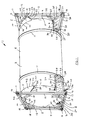
- the container tank 1 is constructed to ISO standards.
- the container tank 1 comprises a pair of transverse end frames 2 and a tank 3 mounted between the end frames 2 by mounting means comprising four upper bearer members 5 and four lower bearer members 6, both of which will be described in more detail below.
- the tank 3 is of stainless steel material and comprises a central cylindrical shell 8 defining a central longitudinal axis 7.
- a pair of end caps 9 close the ends of the cylindrical shell 8.
- the end caps 9 are of dished shape and are convex when viewed from the exterior of the tank 3.
- the end caps 9 are seam welded to the cylindrical shell 8 along seam welds 10.
- a pair of strengthening hoops 11 also of stainless steel material extend around the cylindrical shell 8 of the tank 3 for reinforcing the tank 3 against hoop stresses.
- Each end frame 2 is arranged transversely of the longitudinal axis 7 of the tank 3.
- Each end frame 2 comprises a pair of upstanding side members 12 of box section steel joined by top and bottom cross members 14 and 15, respectively, also of box section steel.
- the side members 12, top and bottom cross members 14 and 15 terminate in and are joined by corner castings 16 which are to ISO standard, and comprise openings 17 to facilitate lifting, stacking, handling and transportation of the container tank 1.
- corner castings 16 will be well known to those skilled in the art.
- Upper connecting members 18 of box section steel extend between the side members 12 and top cross members 14 for carrying the upper bearer members 5.
- Lower connecting members 20 extend between the side members 12 and the bottom cross members 15 for carrying the lower bearer members 6.
- Intermediate connecting members 21 extend from the lower connecting members 20 in a generally diagonal direction towards the corner castings 16 also for carrying the lower bearer members 6.
- the lower bearer members 6 are of substantially similar construction to those described and illustrated in British Patent Application Specification No. 2,168,415A.
- Each lower bearer member 6 comprises a pair of spaced apart side walls 24 of stainless steel plate material joined by end walls 25, 26 and 27 of carbon steel plate material welded to the side walls 24 along seam welds 28.
- Side flanges 29 of stainless steel plate extend sidewardly from the side walls 24 and are welded thereto along seam welds 30.
- the side flanges 29 engage the cylindrical shell 8 of the tank 3 and are shaped at 32 to engage the end caps 9 of the tank 3.
- the lower bearer members 6 are mounted to the tank 3 by welding the side flanges 29 to the cylindrical shell 8 and the end caps 9 along seam welds 34.
- the lower bearer members 6 are mounted on the end frames 2 by welding the side walls 24 to the intermediate connecting members 21 along seam welds 35.
- a portion 36 formed by side walls 37 and an end wall 38 which extend downwardly from the side walls 24 and end wall 26, respectively, of the lower bearer members 6 provide further rigidity to the bearer member.
- Each portion 36 is welded to a corresponding side member 12 of the end frame 2 along a seam weld 40.
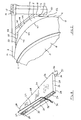
- Each upper bearer member 5 comprises a bearer plate 43 of stainless steel plate material.
- the bearer plates 43 extend in a generally longitudinal direction between the tank 3 and the end frames 2 and terminate at respective ends in a tank engaging end 44 and a frame engaging end 45.
- Each tank engaging end 44 is provided by a transverse tank engaging edge 46 which mounts the bearer plate 43 to the tank 3 and is welded along a seam weld 47 to the tank 3 adjacent the seam weld 10 between the cylindrical shell 8 and the end cap 9.
- the frame engaging end 45 of each bearer plate 43 is formed by a transverse frame engaging edge 48 which mounts the bearer plate 43 to an adjacent end frame 2 and is welded to an upper connecting member 18 along a seam weld 49.
- Each bearer plate 43 is of bent transverse cross section when viewed in the direction of the arrow A, see Figs. 5 and 6, and in this case each bearer plate 43 is of arcuate transverse cross section.
- the curvature of each bearer plate 43 is identical to the curvature of the cylindrical shell 8 of the tank 3 at the position where the bearer plate is mounted to the cylindrical shell 8.
- the curvature of each bearer plate 43 is constant over the entire length of each bearer plate 43 from the tank engaging edge 46 to the frame engaging edge 48.
- the bearer plates 43 are of radius similar to the radius of the cylindrical shell 8 and define an axis which co-incides with the central longitudinal axis 7 of the cylindrical shell 8.
- the bearer plates 43 are concave when viewed from the longitudinal axis 7 of the tank 3.
- the tank engaging edge 46 of each bearer plate 43 is longer than the frame engaging edge 48.
- the edges 46 and 48 are joined by longitudinal side edges 50.
- Each side edge 50 extends from the tank engaging edge 46 and is convex at 52 and converges towards the frame engaging edge 48.
- Each convex portion 52 terminates in a concave portion 53 which extends from the frame engaging edge 48.
- the bearer plates 43 engage the tank 3 at positions substantially halfway between a central horizontal plane 55 and a central vertical plane 56 through the tank 3 and above the horizontal plane 55, see Figs. 3 and 4.
- the bearer plates 43 extend equidistant on both sides of a 45° position which is indicated by the reference numeral 57 towards the horizontal plane 55 and vertical plane 56.
- the end frames 2 are positioned at respective ends of the tank 3 transversely of the longitudinal axis 7 of the tank 3.
- the upper and lower bearer members 5 and 6 are then positioned relative to the end frames 2 and tank 3 ready for welding, and are then welded to the tank 3 and end frames 2.
- the advantages of the container tank 1 according to the invention are many.
- a relatively strong and rigid container tank 1 is provided, while at the same time the container tank 1 is relatively lightweight.
- the bearer plates forming the upper bearer members 5 are of bent transverse cross section, and in this case are of arcuate cross section when viewed in the direction of the arrow A, relatively strong and rigid upper bearer members are provided.
- the weight of the bearer members is considerably lower than the lower bearer members 6, and other bearer members known heretofore.
- the upper bearer units by virtue of the fact that they are constructed of plate material of arcuate transverse cross section are relatively inexpensive and easy to produce, and are also relatively easy and inexpensive to mount.
- FIG. 9 and 10 there is illustrated portion of a container tank also according to the invention indicated generally by the reference numeral 70.
- the container tank 70 is substantially similar to the container tank 1 described with reference to Figs. 1 to 8 and similar components are identified by the same reference numerals.
- the main difference between this container tank 70 and the container tank 1 is that the lower bearer members of the container tank 1 are replaced by lower bearer members 71 of identical construction to the upper bearer members 5.
- the lower bearer members 71 are formed by bearer plates 43 identical to the bearer plates 43 of the container tank 1.
- the lower bearer plates 43 are positioned substantially halfway between the central horizontal plane 55 and central vertical plane 56 and below the horizontal plane 55.
- the tank engaging edge 46 of the lower bearer plates 43 extend equi-distant from the 45° position 57 towards the horizontal plane 55 and vertical plane 56.
- the bearer plates 43 of the bearer members 71 are welded to the lower connecting members 20.
- the frame engaging edges 48 of the bearer plates 43 of the bearer members 71 are welded along seam welds 49 to the respective lower connecting members 20.
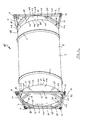
- FIG. 11 and 12 there is illustrated portion of a container tank according to a further embodiment of the invention indicated generally by the reference numeral 80.
- the container tank 80 is substantially similar to the container tank 1 and similar components are identified by the same reference numerals.
- four bearer members 81 are provided for mounting the tank 3 to each adjacent end frame 2.
- Each bearer member 81 is formed by a bearer plate 43 identical to the bearer plates 43 of the container tank 1.
- the bearer plates 43 are positioned around the tank at top and bottom vertical positions 82 which co-incide with the central vertical plane 56 through the tank 3 and at side positions 84 which correspond with the central horizontal plane 55.
- the tank engaging edges 46 of the bearer plates 43 at the top and bottom vertical positions 42 extend equidistant from the vertical position 82 towards the horizontal plane 55 while the bearer plates 43 at the side positions 84 extend equidistant from the side position 84 towards the vertical plane 56.
- the frame engaging edges 48 of the bearer plates 43 are seam welded along seam welds 49 to the respective top and bottom cross members 14 and 15 and side members 12 of the end frames 2.
- the bearer plates 43 are welded along seam welds 47 to the tank 3 adjacent the seam weld 10 of the end caps 9 to the cylindrical shell 8 and are of similar curvature to the cylindrical shell 8.
- the bearer plates 43 are of similar cross section to the bearer plate 43 of the container tank 1 and accordingly define an axis of generation which co-incides with the longitudinal axis 7 of the tank 3.
- the bearer plates may be provided in other positions between the tank and the end frames other than those illustrated in the drawings. Indeed, in certain cases, it is envisaged that the tank may be mounted to each end frame by a single bearer plate. In such cases, it is envisaged that two lower bearer members similar to the lower bearer members of the container tank of Figs. 1 to 8 may be used in combination with the single bearer plate, however, this is not essential, in certain cases it is envisaged that a single bearer plate may be used in combination with any other bearer members of other construction or mounting members. In fact, it is envisaged that the tank may be mounted to each end frame by two bearer plates without any other mounting means or connecting means. Needless to say, while the tanks described with reference to Figs. 9 to 12 have been described as being connected to each end frame by four bearer plates, the tanks may be connected by any other number of bearer plates, either more or less than four.
- the bearer plates and other bearer or mounting members should be symmetrically mounted around vertical and horizontal planes of the tank, this is not essential.
- bearer plates may be provided at the lower portion of the tank while other bearer members or mounting members may be provided at the upper portion of the tank.
- the shape of the longitudinal side edges may be of shape other than that described.
- the longitudinal side edges may be formed having a convex portion and a concave portion.
- the longitudinal side edges in certain cases, may be relatively straight converging edges. In other cases, the longitudinal side edges may be straight parallel edges, in which case, the frame engaging edge of each bearer plate would be of similar length to the tank engaging edge. Indeed, in certain cases, it is envisaged that the tank engaging edge of each bearer plate may be shorter than the frame engaging edge.
- the bearer plates should define an axis of generation which co-incides with the central longitudinal axis of the tank.
- the bearer plates and mounting members have been described as being welded to the tank and end frames, other suitable fixing means may be used.
- the bearer plates and lower bearer members may be mounted to the tank and/or the end frames by bolts, screws, rivets or the like.
- suitable flanges would be provided to carry the bolts, screws or rivets.
- other suitable means for carrying the bolts, screws and rivets may be provided.
- the tank has been described as comprising a central cylindrical shell, the central shell may be of any other cross section, for example, elliptical cross section, ovoid cross section or the like.
- the curvature of the bearer plates would correspond to the curvature of the central shell of the tank adjacent the position where the bearer plates are secured to the central shell.
- the tank may be provided with end caps of other shape and construction besides those described, and it will also be appreciated that end frames of other shape and construction may be provided.
Landscapes
- Engineering & Computer Science (AREA)
- Mechanical Engineering (AREA)
- Filling Or Discharging Of Gas Storage Vessels (AREA)
- Details Of Rigid Or Semi-Rigid Containers (AREA)
Claims (9)
- Réservoir (1) formant conteneur du type comportant un réservoir (3), le réservoir (3) comportant une enveloppe centrale (8) définissant un axe longitudinal central (7) et ayant en coupe au moins partiellement une forme d'arc de cercle transversal, et deux culots (9) d'extrémité fermant les extrémités respectives de l'enveloppe centrale (8), au moins un châssis (2) d'extrémité s'étendant transversalement à l'axe longitudinal (7) en étant adjacent à l'un des culots (9) d'extrémité, et des moyens de montage (5, 6) destinés au montage du réservoir (3) sur le châssis (2) d'extrémité, les moyens de montage (5, 6) comportant au moins une plaque porteuse (43) de matériau en plaque, chaque plaque porteuse (43) s'étendant dans une direction générale longitudinale entre le réservoir (3) et le châssis (2) d'extrémité, et ayant un bord d'extrémité (44, 46) s'étendant transversalement en contact avec le réservoir et un bord d'extrémité (45, 48) s'étendant transversalement en étant longitudinalement écarté en contact avec le châssis, le bord d'extrémité (44, 46) en contact avec le réservoir et le bord d'extrémité (45, 48) en contact avec le châssis étant reliés par des bords latéraux (50), le bord d'extrémité (44, 46) de chaque plaque porteuse (43) en contact avec le réservoir étant en contact avec une extrémité du réservoir en étant adjacent à l'enveloppe centrale (8) au niveau d'une partie en arc de cercle de celle-ci, et le bord d'extrémité (45, 48) en contact avec le châssis étant en contact avec le châssis d'extrémité (2), chaque plaque porteuse (43) ayant une section transversale en arc de cercle, caractérisé en ce que la courbure en coupe transversale de chaque plaque porteuse (43) est constante entre le bord d'extrémité (44, 46) en contact avec le réservoir et le bord d'extrémité (45, 48) en contact avec le châssis, et est à peu près identique à la courbure en coupe transversale de l'enveloppe centrale (8) adjacente au bord d'extrémité (44,46) en contact avec le réservoir.
- Réservoir formant conteneur selon la revendication 1, caractérisé en ce que chaque plaque porteuse (43) est en contact avec l'enveloppe centrale (8) du réservoir (3).
- Réservoir formant conteneur selon la revendication 1 ou 2, caractérisé en ce que le bord d'extrémité (44, 46) de chaque plaque porteuse (43) en contact avec le réservoir est plus long que le bord formant extrémité (45, 48) en contact avec le châssis, et en ce que le bord d'extrémité (44, 46) en contact avec le réservoir et le bord d'extrémité (45, 48) en contact avec le châssis sont reliés par des bords (50) formant côté longitudinal convergeant vers le bord d'extrémité (45, 48) en contact avec le châssis.
- Réservoir formant conteneur selon l'une quelconque des revendications précédentes, caractérisé en ce que chaque bord (50) formant côté longitudinal de chaque plaque porteuse (43) est constitué d'une partie convexe (52) s'étendant à partir du bord d'extrémité (44, 46) en contact avec le réservoir vers une partie concave (53) du bord (50) formant côté longitudinal s'étendant à partir du bord d'extrémité (45, 48) en contact avec le châssis.
- Réservoir formant conteneur selon l'une quelconque des revendications précédentes, caractérisé en ce que le bord d'extrémité (44, 46) de chaque plaque porteuse (43) en contact avec le réservoir est soudé en cordon (47) sur à peu près toute sa longueur située sur le réservoir (3) et le bord d'extrémité (45, 48) en contact avec le châssis est soudé par cordon (49) sur à peu près toute sa longueur située sur le châssis d'extrémité (2).
- Réservoir formant conteneur selon l'une quelconque des revendications précédentes, caractérisé en ce que deux châssis d'extrémité (2) sont prévus s'étendant transversalement par rapport à l'axe longitudinal central (7) du réservoir (3), le réservoir (3) étant monté entre les deux châssis d'extrémité (2), et le réservoir (3) étant monté sur les châssis d'extrémité (2) par les plaques porteuses respectives (43).
- Réservoir formant conteneur selon l'une quelconque des revendications précédentes, caractérisé en ce que le réservoir (3) est monté sur chaque châssis d'extrémité (2) par l'intermédiaire de deux plaques porteuses (43), les plaques porteuses (43) étant positionnées sur le réservoir (3) dans des positions situées à peu près à mi-chemin entre un plan axial horizontal (55) et un plan axial vertical (56) du réservoir (3), le bord d'extrémité (44, 46) de chaque plaque porteuse (43) en contact avec le réservoir s'étendant sur chaque côté d'une position intermédiaire (5) à 45° desdits plans axiaux (55, 56), respectivement, vers le plan horizontal (55) et le plan vertical (56).
- Réservoir formant conteneur selon l'une quelconque des revendications précédentes, caractérisé en ce que l'axe défini par la courbure de chaque plaque porteuse (43) coïncide avec l'axe longitudinal central (7) du réservoir (3).
- Réservoir formant conteneur selon l'une quelconque des revendications précédentes, caractérisé en ce que l'enveloppe centrale (8) du réservoir (3) a une coupe transversale circulaire et en ce que chaque plaque porteuse (43) a une coupe transversale partiellement circulaire.
Applications Claiming Priority (2)
| Application Number | Priority Date | Filing Date | Title |
|---|---|---|---|
| IE346889A IE63462B1 (en) | 1989-10-27 | 1989-10-27 | A container tank |
| IE346889 | 1989-10-27 |
Publications (2)
| Publication Number | Publication Date |
|---|---|
| EP0425190A1 EP0425190A1 (fr) | 1991-05-02 |
| EP0425190B1 true EP0425190B1 (fr) | 1993-08-25 |
Family
ID=11038699
Family Applications (1)
| Application Number | Title | Priority Date | Filing Date |
|---|---|---|---|
| EP90311400A Expired - Lifetime EP0425190B1 (fr) | 1989-10-27 | 1990-10-17 | Conteneur-citerne |
Country Status (5)
| Country | Link |
|---|---|
| US (1) | US5083673A (fr) |
| EP (1) | EP0425190B1 (fr) |
| BE (1) | BE1002411A6 (fr) |
| DE (1) | DE69002918T2 (fr) |
| IE (1) | IE63462B1 (fr) |
Cited By (1)
| Publication number | Priority date | Publication date | Assignee | Title |
|---|---|---|---|---|
| RU2207310C1 (ru) * | 2001-12-14 | 2003-06-27 | Общество с ограниченной ответственностью Научно-технический центр "Металлкомпозит" | Контейнер-цистерна |
Families Citing this family (29)
| Publication number | Priority date | Publication date | Assignee | Title |
|---|---|---|---|---|
| GB9115905D0 (en) * | 1991-07-23 | 1991-09-04 | Material Control Eng Ltd | Material handling apparatus |
| US5348176A (en) * | 1991-11-15 | 1994-09-20 | Rosby Corporation | High-cube top lift cargo carrier structure |
| RU2017673C1 (ru) * | 1991-12-28 | 1994-08-15 | Мариупольский концерн "Азовмаш" | Грузовой контейнер |
| US5353967A (en) * | 1993-04-20 | 1994-10-11 | Northbrook Rail Corporation | Dry bulk pressure differential container |
| US5779077A (en) * | 1993-05-21 | 1998-07-14 | Container Design Limited | Container tank |
| DE9317638U1 (de) * | 1993-11-18 | 1995-04-20 | Westerwälder Eisenwerk Gerhard GmbH, 57586 Weitefeld | Tankcontainer |
| ATE199832T1 (de) * | 1994-01-18 | 2001-04-15 | Sci Can | Sterilisationskammer zur dampfsterilisation von ärztlichen instrumenten, implantaten und ähnlichem |
| KR100395069B1 (ko) | 1996-02-16 | 2003-12-24 | 알코아 인코포레이티드 | 유동성건조제품의통합수송및저장을위한컨테이너모듈 |
| US5960974A (en) * | 1996-10-03 | 1999-10-05 | Advance Engineered Products Ltd. | Intermodal bulk container |
| US5779078A (en) * | 1996-11-21 | 1998-07-14 | Reddy; Neil | Intermodal container tank construction |
| DE29705851U1 (de) * | 1997-04-02 | 1998-08-06 | Gerhard Engineering GmbH, 57586 Weitefeld | Tankcontainer |
| RU2194660C2 (ru) * | 2001-03-15 | 2002-12-20 | Открытое акционерное общество "Рузхиммаш" | Контейнер-цистерна |
| US7104425B2 (en) * | 2002-10-18 | 2006-09-12 | Le Roy Curtis W | Intermodal bulk dry particulate cargo container and method |
| DE202006008574U1 (de) | 2006-05-30 | 2007-10-11 | WEW Westerwälder Eisenwerk GmbH | Tankcontainer |
| DE102008063321B4 (de) * | 2008-12-30 | 2010-11-18 | WEW Westerwälder Eisenwerk GmbH | Tankcontainer |
| US20100193077A1 (en) * | 2009-02-03 | 2010-08-05 | Peak Innovations, Inc. | Containerized silo |
| AU2010260462B2 (en) * | 2009-06-18 | 2015-10-22 | International Transport Equipment Corporation | Intermodal tank transport system, components, and methods |
| EA201491137A1 (ru) * | 2011-12-05 | 2015-01-30 | Блю Вэйв Ко С.А. | Контейнер iso для смешанной перевозки |
| US10202236B2 (en) | 2014-05-06 | 2019-02-12 | JWF Industries | Portable vertical fluid storage tank |
| US11091317B2 (en) | 2014-05-06 | 2021-08-17 | Jwf Industries, Inc. | Vertical fluid storage tank with connecting ports |
| USD819778S1 (en) | 2014-05-08 | 2018-06-05 | JWF Industries | Vertical fluid storage tank |
| AT518234B1 (de) * | 2016-01-26 | 2017-12-15 | Ing Peter Wanek-Pusset Dipl | Tankcontainer |
| CN107035964A (zh) * | 2016-02-04 | 2017-08-11 | 南通中集罐式储运设备制造有限公司 | 罐式集装箱 |
| RU175966U1 (ru) * | 2017-03-13 | 2017-12-25 | Акционерное общество "Научно-внедренческий центр "Вагоны" (АО "НВЦ "Вагоны") | Съемный кузов-цистерна |
| CN107335934B (zh) * | 2017-07-04 | 2019-03-01 | 中国核工业第五建设有限公司 | Lng罐内加强圈的安装方法 |
| RU182375U9 (ru) * | 2018-04-27 | 2022-04-21 | РЕЙЛ 1520 АйПи ЛТД | Контейнер-цистерна |
| US11691808B2 (en) * | 2018-06-09 | 2023-07-04 | Ondrej Kotora | Dual purpose intermodal tank container |
| CN110817146B (zh) * | 2018-08-09 | 2025-10-03 | 中集安瑞环科技股份有限公司 | 罐式集装箱 |
| CN108945840A (zh) * | 2018-09-29 | 2018-12-07 | 中车西安车辆有限公司 | 一种罐式集装箱 |
Family Cites Families (9)
| Publication number | Priority date | Publication date | Assignee | Title |
|---|---|---|---|---|
| US3971491A (en) * | 1975-10-14 | 1976-07-27 | General American Transportation Corporation | Intermodal tank container |
| GB2013624B (en) * | 1977-10-20 | 1982-03-24 | Lambert G | Mounting of hollow sturctures |
| DE2828349C2 (de) * | 1978-06-28 | 1983-02-24 | Westerwälder Eisenwerk Gerhard GmbH, 5241 Weitefeld | Frachtcontainer für fließfähige Stoffe |
| DE3034512A1 (de) * | 1980-09-12 | 1982-04-29 | Gerhard KG, 5241 Weitefeld | Frachtcontainer |
| FR2512481A1 (fr) * | 1981-09-04 | 1983-03-11 | Stein Industrie | Dispositif de supportage tangentiel d'un reservoir horizontal d'epaisseur faible par rapport a son diametre |
| DE3410218A1 (de) * | 1984-03-16 | 1985-09-19 | Schering AG, Berlin und Bergkamen, 1000 Berlin | Tergurid als antihypertensivum |
| IE55735B1 (en) * | 1984-12-07 | 1991-01-02 | Container Eng Ltd | Improvements in and relating to container tanks |
| DE3624430A1 (de) * | 1986-07-18 | 1988-02-04 | Westerwaelder Eisen Gerhard | Tankanordnung |
| DE8811024U1 (de) * | 1988-08-31 | 1989-12-28 | Westerwälder Eisenwerk Gerhard GmbH, 57586 Weitefeld | Transporttank |
-
1989
- 1989-10-27 IE IE346889A patent/IE63462B1/en not_active IP Right Cessation
-
1990
- 1990-10-17 EP EP90311400A patent/EP0425190B1/fr not_active Expired - Lifetime
- 1990-10-17 DE DE90311400T patent/DE69002918T2/de not_active Expired - Fee Related
- 1990-10-24 US US07/605,223 patent/US5083673A/en not_active Expired - Lifetime
- 1990-10-26 BE BE9001021A patent/BE1002411A6/fr not_active IP Right Cessation
Cited By (1)
| Publication number | Priority date | Publication date | Assignee | Title |
|---|---|---|---|---|
| RU2207310C1 (ru) * | 2001-12-14 | 2003-06-27 | Общество с ограниченной ответственностью Научно-технический центр "Металлкомпозит" | Контейнер-цистерна |
Also Published As
| Publication number | Publication date |
|---|---|
| DE69002918T2 (de) | 1994-04-21 |
| IE63462B1 (en) | 1995-04-19 |
| DE69002918D1 (de) | 1993-09-30 |
| IE893468A1 (en) | 1991-05-08 |
| BE1002411A6 (fr) | 1991-01-29 |
| EP0425190A1 (fr) | 1991-05-02 |
| US5083673A (en) | 1992-01-28 |
Similar Documents
| Publication | Publication Date | Title |
|---|---|---|
| EP0425190B1 (fr) | Conteneur-citerne | |
| US3912103A (en) | Pressure-tight transport container for flowable goods | |
| US3799383A (en) | Transcontainer for flowable material | |
| EP0880461B1 (fr) | Module conteneur pour le transport multimodal et le stockage d'un produit fluide sec | |
| US6059372A (en) | Hopper bottom trailer | |
| US4593832A (en) | Freight container | |
| US4703699A (en) | Lightweight container car | |
| US3814290A (en) | Freight containers for flowable goods | |
| EP0701526B1 (fr) | Conteneur-reservoir | |
| EP3792200B1 (fr) | Conteneur-citerne | |
| US4356925A (en) | Pressure-resistant container for liquids, gases or loose material composed of two or more shells | |
| US4955956A (en) | Transport tank | |
| JPH02205553A (ja) | 液体及び細かく分散したばら積み材料を運搬及び/又は貯蔵する容器 | |
| US5967353A (en) | Tank container | |
| US4813567A (en) | Freight containers | |
| JPH0398890A (ja) | スワップタンク | |
| GB2168415A (en) | Improvements in and relating to container tanks | |
| US4421243A (en) | Container, particularly for materials in particles | |
| US4854462A (en) | Tank container | |
| NO159783B (no) | Sammensatt profil for konstruksjonsformaal. | |
| RU2039693C1 (ru) | Контейнер-цистерна | |
| US5779078A (en) | Intermodal container tank construction | |
| EP0569431B1 (fr) | Accessoire de levage destine aux conteneurs de marchandises | |
| US5348175A (en) | Lift fitting for cargo containers | |
| RU2143992C1 (ru) | Контейнер-цистерна |
Legal Events
| Date | Code | Title | Description |
|---|---|---|---|
| PUAI | Public reference made under article 153(3) epc to a published international application that has entered the european phase |
Free format text: ORIGINAL CODE: 0009012 |
|
| AK | Designated contracting states |
Kind code of ref document: A1 Designated state(s): DE FR GB |
|
| 17P | Request for examination filed |
Effective date: 19911025 |
|
| 17Q | First examination report despatched |
Effective date: 19920806 |
|
| GRAA | (expected) grant |
Free format text: ORIGINAL CODE: 0009210 |
|
| AK | Designated contracting states |
Kind code of ref document: B1 Designated state(s): DE FR GB |
|
| ET | Fr: translation filed | ||
| REF | Corresponds to: |
Ref document number: 69002918 Country of ref document: DE Date of ref document: 19930930 |
|
| PLBI | Opposition filed |
Free format text: ORIGINAL CODE: 0009260 |
|
| 26 | Opposition filed |
Opponent name: WESTERWAELDER EISENWERK GERHARD GMBH Effective date: 19931116 |
|
| PLBN | Opposition rejected |
Free format text: ORIGINAL CODE: 0009273 |
|
| STAA | Information on the status of an ep patent application or granted ep patent |
Free format text: STATUS: OPPOSITION REJECTED |
|
| 27O | Opposition rejected |
Effective date: 19950729 |
|
| REG | Reference to a national code |
Ref country code: GB Ref legal event code: IF02 |
|
| PGFP | Annual fee paid to national office [announced via postgrant information from national office to epo] |
Ref country code: GB Payment date: 20020923 Year of fee payment: 13 |
|
| PGFP | Annual fee paid to national office [announced via postgrant information from national office to epo] |
Ref country code: DE Payment date: 20021017 Year of fee payment: 13 |
|
| PGFP | Annual fee paid to national office [announced via postgrant information from national office to epo] |
Ref country code: FR Payment date: 20021030 Year of fee payment: 13 |
|
| PG25 | Lapsed in a contracting state [announced via postgrant information from national office to epo] |
Ref country code: GB Free format text: LAPSE BECAUSE OF NON-PAYMENT OF DUE FEES Effective date: 20031017 |
|
| PG25 | Lapsed in a contracting state [announced via postgrant information from national office to epo] |
Ref country code: DE Free format text: LAPSE BECAUSE OF NON-PAYMENT OF DUE FEES Effective date: 20040501 |
|
| GBPC | Gb: european patent ceased through non-payment of renewal fee |
Effective date: 20031017 |
|
| PG25 | Lapsed in a contracting state [announced via postgrant information from national office to epo] |
Ref country code: FR Free format text: LAPSE BECAUSE OF NON-PAYMENT OF DUE FEES Effective date: 20040630 |
|
| REG | Reference to a national code |
Ref country code: FR Ref legal event code: ST |