EP0425256A2 - Verfahren und Vorrichtung zum Einbringen von Trocknungsmaterialien in Fensterabstandsrahmen - Google Patents
Verfahren und Vorrichtung zum Einbringen von Trocknungsmaterialien in Fensterabstandsrahmen Download PDFInfo
- Publication number
- EP0425256A2 EP0425256A2 EP90311632A EP90311632A EP0425256A2 EP 0425256 A2 EP0425256 A2 EP 0425256A2 EP 90311632 A EP90311632 A EP 90311632A EP 90311632 A EP90311632 A EP 90311632A EP 0425256 A2 EP0425256 A2 EP 0425256A2
- Authority
- EP
- European Patent Office
- Prior art keywords
- chamber
- desiccant material
- frame member
- accordance
- desiccant
- Prior art date
- Legal status (The legal status is an assumption and is not a legal conclusion. Google has not performed a legal analysis and makes no representation as to the accuracy of the status listed.)
- Withdrawn
Links
- 239000002274 desiccant Substances 0.000 title claims abstract description 76
- 239000000463 material Substances 0.000 title claims abstract description 52
- 125000006850 spacer group Chemical group 0.000 title claims abstract description 25
- 238000000034 method Methods 0.000 title claims abstract description 20
- 238000004891 communication Methods 0.000 claims abstract description 9
- 239000002245 particle Substances 0.000 claims description 12
- 238000000151 deposition Methods 0.000 claims description 6
- 239000012530 fluid Substances 0.000 claims description 4
- 238000001914 filtration Methods 0.000 claims description 2
- 238000005452 bending Methods 0.000 claims 1
- 239000011521 glass Substances 0.000 description 6
- 239000000428 dust Substances 0.000 description 3
- 230000005484 gravity Effects 0.000 description 2
- 238000003780 insertion Methods 0.000 description 2
- 230000037431 insertion Effects 0.000 description 2
- VYPSYNLAJGMNEJ-UHFFFAOYSA-N Silicium dioxide Chemical compound O=[Si]=O VYPSYNLAJGMNEJ-UHFFFAOYSA-N 0.000 description 1
- 229910000831 Steel Inorganic materials 0.000 description 1
- 239000002250 absorbent Substances 0.000 description 1
- 230000002745 absorbent Effects 0.000 description 1
- 229910052782 aluminium Inorganic materials 0.000 description 1
- 238000013459 approach Methods 0.000 description 1
- 230000015572 biosynthetic process Effects 0.000 description 1
- 230000000903 blocking effect Effects 0.000 description 1
- 238000009833 condensation Methods 0.000 description 1
- 230000005494 condensation Effects 0.000 description 1
- 238000010276 construction Methods 0.000 description 1
- 239000012024 dehydrating agents Substances 0.000 description 1
- 230000000881 depressing effect Effects 0.000 description 1
- 238000009826 distribution Methods 0.000 description 1
- 239000004744 fabric Substances 0.000 description 1
- 239000008187 granular material Substances 0.000 description 1
- 231100000206 health hazard Toxicity 0.000 description 1
- 230000001939 inductive effect Effects 0.000 description 1
- 238000002347 injection Methods 0.000 description 1
- 239000007924 injection Substances 0.000 description 1
- 238000009413 insulation Methods 0.000 description 1
- 238000012423 maintenance Methods 0.000 description 1
- 238000004519 manufacturing process Methods 0.000 description 1
- 230000013011 mating Effects 0.000 description 1
- 238000012986 modification Methods 0.000 description 1
- 230000004048 modification Effects 0.000 description 1
- 238000004806 packaging method and process Methods 0.000 description 1
- 238000005086 pumping Methods 0.000 description 1
- 239000003566 sealing material Substances 0.000 description 1
- 239000000741 silica gel Substances 0.000 description 1
- 229910002027 silica gel Inorganic materials 0.000 description 1
- 239000010959 steel Substances 0.000 description 1
- 239000000126 substance Substances 0.000 description 1
Images

Classifications
-
- E—FIXED CONSTRUCTIONS
- E06—DOORS, WINDOWS, SHUTTERS, OR ROLLER BLINDS IN GENERAL; LADDERS
- E06B—FIXED OR MOVABLE CLOSURES FOR OPENINGS IN BUILDINGS, VEHICLES, FENCES OR LIKE ENCLOSURES IN GENERAL, e.g. DOORS, WINDOWS, BLINDS, GATES
- E06B3/00—Window sashes, door leaves, or like elements for closing wall or like openings; Layout of fixed or moving closures, e.g. windows in wall or like openings; Features of rigidly-mounted outer frames relating to the mounting of wing frames
- E06B3/66—Units comprising two or more parallel glass or like panes permanently secured together
- E06B3/673—Assembling the units
- E06B3/67304—Preparing rigid spacer members before assembly
- E06B3/67317—Filling of hollow spacer elements with absorbants; Closing off the spacers thereafter
Definitions
- This invention relates to dispensing comminuted granular materials, such as, a desiccant material; and more particularly relates to a method and apparatus for introducing desiccant materials under pressure into window pane spacers, such as, hollow aluminum spacer frames employed in the fabrication of insulated glass units.
- Desiccant materials are utilized in fine, granular form to fill hollow frames, such as, the hollow spacer frames for insulated glass units in order to minimize the formation of condensation on the inside surfaces between the window panes.
- hollow frames such as, the hollow spacer frames for insulated glass units
- Representative of approaches which have been followed in the past is U.S. letters Patent No. 3,183,560 to E. Brichard where a dehydrating agent is introduced under vacuum into a tube.
- a silica gel is introduced into hollow frame sections for a window; and in U.S. Letters Patent No. 4,151,696 to R. N.
- Knights et al the material is a viscous sealing material which is injected under pressure by means of a pumping unit through a series of injection nozzles.
- Other patents of interest are U.S. Letters Patent Nos. 2,037,893 to Greenan; 3,280,523 to C. E. Stroud et al; 4,261,145 to H. Brocking; 4,660,271 to K. Lenhardt and 4,698,891 to R. Borys.
- an apparatus for depositing a desiccant material in particle form into an open-ended hollow frame member characterised in that the apparatus comprises a normally sealed chamber containing a desiccant material; a fill head including a discharge port in communication with the interior of said chamber and having means on said fill head for releasably clamping at least one open end of said frame member in alignment with said discharge port; and means for pressurizing said chamber thereby forcing said desiccant material through said discharge port into said open end of said frame member.
- a method of dispensing a desiccant material in particle form into an open-ended hollow elongated frame member characterised in that the method comprises the steps of depositing the desiccant material into a normally sealed chamber; positioning said open end of said frame member in communication with the interior of said chamber; and pressurizing said chamber with a gaseous fluid thereby forcing said desiccant material under pressure into said frame member.
- a method of dispensing particulate desiccant materials into the open-ended adjacent legs of a window spacer frame member characterised in that the method comprises the steps of depositing the desiccant material into a chamber; positioning the open ends of said legs of said frame member in communication with the interior of said chamber; and pressurizing said chamber with air to simultaneously force the desiccant material into each of said legs of said frame member for a predetermined time period.
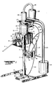
- a desiccant filling apparatus 10 which is broadly comprised of a base 13, a support stand 12 having a telescoping standard 14 and upon which is mounted a control housing 16.
- a fill head 18 is rotably mounted in one sidewall 19 of the housing 16 for the purpose of receiving adjacent free legs of a rectangular spacer frame member F and filling the legs F with a desiccant material represented at D which is supplied from a chamber 20 mounted on top surface 21 of the control housing 16.
- a supply tube 22 extends from the lower end of the chamber 20 for the purpose of delivering desiccant particles from the chamber 20 into the fill head, and the chamber 20 is pressurized by selectively admitting air under pressure from line 23.
- the legs of a spacer frame are perforated along their inner edges, and accordingly, a moisture-absorbing or desiccant material is inserted into at least a pair of the legs to absorb any moisture that would condense on the inside surfaces between the two parallel sheets of glass of an insulated glass unit, not shown.
- a suitable type of desiccant material is an insulating glass absorbent material manufactured and sold by W. R. Grace & Co. of Baltimore, Maryland and is characterized by being a fine bead-like substance.
- One problem in handling this material, particularly in forcing the material into limited spaces or openings for insulation purposes is its tendency to create dust and to the extent that it can become a health hazard.
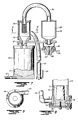
- a pick-up tube 25 extends from the reservoir upwardly into a filter bowl or separator 26 which is mounted on a platform 27 above the chamber 20.
- a vacuum is established in the reservoir 24 by directing air under pressure through an air line 28 into air amplifiers at the lower ends of the tube 25 and the filter bowl 29.
- This vacuum or negative pressure will operate to induce the flow of desiccant material from the reservoir through the pick-up tube 25 into the filter 26.
- the filter 26 will prevent any of the larger desiccant particles from passing through the connecting tube 30 between the filters 26 and 29.
- the larger particles of the desiccant material D will therefore be free to advance by gravity into the chamber 20, and any air will pass through the filter 29 and be exhausted to the atmosphere.
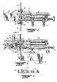
- the fill head 18 comprises an elongated, inverted V-shaped body 40 and a circular mounting plate 38 at the rearward end of the body 40 which is secured to the end of a bolt 41 projecting through the wall panel 19 of the control housing 16.
- the mounting plate 38 is releasably secured against rotation to the surrounding edge of an opening in the panel 19 by clamping screws 39 which extend through the plate and threadedly engage clamping plates 39′ behind the panel 19 to tighten or lock the plate 38 against rotation.
- clamping screws 39 When the clamping screws 39 are loosened, the fill head body and the plate 38 can be rotated for a purpose to be hereinafter described.
- the body 40 has inclined surfaces 42 on opposite sides which slope or diverge downwardly and away from an upper feed area 44 which receives the lower end of the supply tube 22.
- a fixed guide block 46 and movable block 47 are disposed on each of the inclined surfaces 42 to define a common entrance 48 for insertion of a leg or side of a spacer frame F.
- the fixed block 46 has an extension plate 49 which extends across the entrance in spaced parallel relation to each inclined surface 42 so as to define a substantially rectangular space or opening at the entrance for insertion of the spacer frame, as best seen from Figure 6.
- Each movable guide block 47 is attached with shoulder bolts 47′ slidable in an elongated slot 50 under the control of a double-acting cylinder 52.
- Each cylinder 52 includes a piston rod 53 pivotally connected to a slide bar 54 which rides beneath each inclined surface 40 and is connected by the shoulder bolts 47′ to the block 47 to control its movement along the slot 50 toward and away from the fixed block 46 in response to air under pressure directel into one of the pressure lines L3 and L4.
- the block 47 is selectively movable into a closed position, as shown in Figure 3, to clamp a spacer frame between the blocks 46 and 47 with the upper end of the spacer frame in communication with a discharge port 56 extending downwardly from the feed area 44.
- the tube 22 is movable lengthwise of the feed tube 44 into and out of alignment with the supply ports 56 under the control of a double-acting cylinder 62 having air pressure lines L1 and L2.
- a piston rod 63 is pivotally connected to a slide bar 64 with the lower end of the tube 22 affixed to the slide bar for advancement under the control of the piston rod 63.
- Spring-loaded steel balls 65 yieldingly engage the undersurface of the plate 44 to apply a controlled clamping force to the mating surfaces of the slide valve 64.
- the lower end of the pick-up tube 25 has an air flow amplifier 70.
- the air amplifier 70 includes a generally conical plug 71 which is centered within the throat region 72, and air is delivered under pressure through the line 28 to flow through the circumferential inlet 73 and upwardly across the venturi formed between the throat 72 and plug 71 in order to induce upward flow of the desiccant material from the reservoir 24 through the lower open end 74.
- a bracket 75 is disposed across the opening 74 for the purpose of mounting the plug 71 in centered relation to the throat 72.
- the desiccant material is drawn with the air through the tube 25 and is fed tangentially into the separator 26 so that the air will follow a circular path tending to draw the desiccant from the air against the wall of the separator and will roll downwardly by gravity through funnel 78 into the desiccant chamber 20.
- a butterfly valve 80 is positioned across the lower end of the funnel and is controlled by a pneumatic actuator 81, illustrated in Figure 1, to seal off the separator 26 from the chamber 20 during desiccant fill operations when dessicant is being discharged under pressure from the chamber 20 through the fill head 18.
- the butterfly valve 80 is opened by the actuator 81 which in turn is energized by directing air under pressure by a line 82 from a pilot operated valve, not shown, in the housing 32.
- a manually operated push button valve 84 on the side of the valve housing 32 provides pilot pressure for operation of the valve for the actuator 81 as well as a valve, not shown, which opens the inlet line L to initiate the air conveyor operation for refilling of the chamber 20.
- a second fluid flow amplifier 86 is disposed at the lower end of the filter 29 having a frustoconical plug 87 centered within a generally venturi-shaped throat region 88 and receives air under pressure via the pressure line 28 from the control housing 32. This air is directed into a circumferential recess and caused to pass downwardly through the venturi region 88 to create a negative pressure inducing the air to flow through the filter 29 and overcome any pressure loss across the filter medium 29′.
- a minimum velocity of air must be maintained in the pick-up tube 25 in order to carry the largest particles from the desiccant reservoir 25 upwardly into the desiccant chamber; otherwise, lower velocities will transport only the smaller particles or not at all. Accordingly, a minimum outlet pressure from the fluid amplifier 70 is required to overcome the maximum pressure head which will develop as a result of lifting the desiccant through the vertical distance into the desiccant chamber 20.
- a cyclone separator is employed to separate the desiccant material from the air.
- the air flow will follow a circular path through the separator in order to encourage the desiccant to advance outwardly against the wall of the separator and to roll downwardly through the funnel-shaped area 78.
- a filter screen is mounted in the center of the separator which is coarse enough to allow air and dust particles to exit the top of the separator 26 while blocking the larger desiccant particles.
- a cloth bag 29′ may provide filtration down to 40 microns.
- a filter paper can be inserted to filter out particles down to the order of 5 microns.
- the air amplifier 86 is mounted at the lower end of the filter 29 to overcome the pressure drop across the filter and to increase the pressure differential across the pick-up tube 25.
- one suitable form of air amplifier for the amplifiers and 86 is that sold under the trademark "TRANSVECTOR” by the Vortec Corporation, Cincinnati, Ohio.
- the foot valve 34 includes pressure and return lines designated at 35 into the main housing 16 for controlling the desiccant fill operation.
- air is directed under pressure from an external compressed air source, not shown, via the inlet line L through a separate pressure line 23′ to the control housing 16.
- the actuation of the foot valve 34 will permit air under pressure to be directed from the pressure line 23′ through the upper tube 23 into the top of the chamber 20 in order to pressurize the desiccant the chamber 20.
- a fill timer control T on the side of the control housing may be set to regulate the time of each fill; also, a clamping pressure regulator C permits adjustment of the degree of clamping pressure by controlling the amount of air pressure directed into the double acting piston 52 for the slide block 47.
- a spacer frame F is of generally rectangular cross-sectional configuration with upper inclined sides or legs terminating in free ends, such as, illustrated in Figure 6. In accordance with well-known practice, it is necessary only to fill two sides of a spacer frame in order to efficiently dry or remove moisture along the window surfaces when installed.
- the fill timer T will be set to assure introduction of a specific volume or quantity of desiccant which can be loaded under pressure into the two legs of the frame.
- the legs of the frame are inserted into the entrances 48 on opposite sides of the end 18 followed by depressing the foot valve 34.
- the foot valve when the foot valve is activated, it will cause the clamp or slide blocks 47 to be urged against the ends of the spacer frame, advance the fill tube 22 to a position aligned with the ports 56, followed by introduction of air under pressure into the desiccant chamber D to positively force desiccant material through the fill tube 22 into the legs of the spacer frame and for a time period as determined by the fill switch T.
- the sequence is reversed to interrupt the flow of air under pressure to the chamber 20, retract the supply tube 22 to a closed position, and release the clamping blocks 47.
- the spacer frame is then removed and a corner splice or plug is inserted into the free ends of the legs of the spacer frame to retain the desiccant within the frame.
- the butterfly valve 80 remains in a closed position to seal the chamber 20.
- the valve 80 is opened by the pneumatic actuator 81 and air under pressure is then introduced through the pressure line 28 to refill the chamber 20 in the manner described.
- the air conveyor sequence for refilling the chamber is initiated by the conveyor button 84 on the valve housing 32.
- the desiccant chamber may be filled manually without the assistance of the air conveyor as described.
- the fill head 18 can be rotated within the face plate 19 by loosening the clamps 39, for example, to faciliate handling extended lengths of spacer frames without interference from the floor surface.
- one side of the fill head 18 may be plugged or blocked off so that the desiccant material is directed only through the raised or upper port 56.
- the adjustable telescoping standard 14 enables suitable height adjustment of the machine according to the size of the spacer frame to be filled.
- the described embodiment of the present invention provides a method and apparatus for dispensing desiccant materials and in particular for their introduction under pressure into spacer frames of the type employed in insulated glass units.
- the method and apparatus described enables desiccant material to be injected in a minimum amount of time at a predetermined pressure and remains flexible enough to be used in filling a wide range of lengths and sizes of spacer frames.
- the described embodiment provides a means for conveying the desiccant material from a bulk packaging container into a chamber which can be pressurized in such a way as to minimize distribution of dust or of wasting or spilling the desiccant material.
- the described apparatus is both modular and transportable while requiring a minimum amount of maintenance.
Landscapes
- Engineering & Computer Science (AREA)
- Civil Engineering (AREA)
- Structural Engineering (AREA)
- Securing Of Glass Panes Or The Like (AREA)
Applications Claiming Priority (2)
| Application Number | Priority Date | Filing Date | Title |
|---|---|---|---|
| US42500689A | 1989-10-23 | 1989-10-23 | |
| US425006 | 1989-10-23 |
Publications (2)
| Publication Number | Publication Date |
|---|---|
| EP0425256A2 true EP0425256A2 (de) | 1991-05-02 |
| EP0425256A3 EP0425256A3 (en) | 1992-03-04 |
Family
ID=23684751
Family Applications (1)
| Application Number | Title | Priority Date | Filing Date |
|---|---|---|---|
| EP19900311632 Withdrawn EP0425256A3 (en) | 1989-10-23 | 1990-10-23 | Method and apparatus for dispensing desiccant materials into window spacer frames |
Country Status (1)
| Country | Link |
|---|---|
| EP (1) | EP0425256A3 (de) |
Cited By (4)
| Publication number | Priority date | Publication date | Assignee | Title |
|---|---|---|---|---|
| WO1992010635A1 (en) * | 1990-12-05 | 1992-06-25 | Skovgaard & Co. A/S | A method and an apparatus for filling a closed spacer frame with a drying agent |
| EP0600240A1 (de) * | 1992-12-02 | 1994-06-08 | Norsk Hydro A/S | Verfahren zur Verbesserung der Wärmedämmung an Rahmen aus wärmegedämmten Verbundprofilen |
| EP0698718A1 (de) * | 1994-08-11 | 1996-02-28 | Lenhardt Maschinenbau GmbH | Abstandhalterrahmen für Isolierglasscheiben und Verfahren zu seiner Herstellung |
| EP3447230A1 (de) * | 2017-08-23 | 2019-02-27 | Rottler und Rüdiger und Partner GmbH | Verfahren und vorrichtung zur herstellung von abstandhalterahmen für isolierglasscheiben |
Family Cites Families (2)
| Publication number | Priority date | Publication date | Assignee | Title |
|---|---|---|---|---|
| DE3710694A1 (de) * | 1987-03-31 | 1988-10-13 | Karl Lenhardt | Verfahren und vorrichtung zum befuellen von geraden hohlprofilstaeben fuer abstandhalterrahmen in isolierglasscheiben mit einem koernigen trockenmittel |
| DE3740922A1 (de) * | 1987-12-03 | 1989-06-22 | Bayer Isolierglasfab Kg | Verfahren und vorrichtung zur herstellung eines abstandhalter-rahmens |
-
1990
- 1990-10-23 EP EP19900311632 patent/EP0425256A3/en not_active Withdrawn
Cited By (4)
| Publication number | Priority date | Publication date | Assignee | Title |
|---|---|---|---|---|
| WO1992010635A1 (en) * | 1990-12-05 | 1992-06-25 | Skovgaard & Co. A/S | A method and an apparatus for filling a closed spacer frame with a drying agent |
| EP0600240A1 (de) * | 1992-12-02 | 1994-06-08 | Norsk Hydro A/S | Verfahren zur Verbesserung der Wärmedämmung an Rahmen aus wärmegedämmten Verbundprofilen |
| EP0698718A1 (de) * | 1994-08-11 | 1996-02-28 | Lenhardt Maschinenbau GmbH | Abstandhalterrahmen für Isolierglasscheiben und Verfahren zu seiner Herstellung |
| EP3447230A1 (de) * | 2017-08-23 | 2019-02-27 | Rottler und Rüdiger und Partner GmbH | Verfahren und vorrichtung zur herstellung von abstandhalterahmen für isolierglasscheiben |
Also Published As
| Publication number | Publication date |
|---|---|
| EP0425256A3 (en) | 1992-03-04 |
Similar Documents
| Publication | Publication Date | Title |
|---|---|---|
| US4369084A (en) | Apparatus for producing insulating glass filled with a gas other than air | |
| JPH0840754A (ja) | 内室に重質ガスを充填した絶縁ガラス板の組立方法及び絶縁ガラス板に重質ガスを充填するための装置 | |
| US5762739A (en) | Process and apparatus for assembling insulating glass panes which are filled with a gas other than air | |
| US4219054A (en) | Method and apparatus for filling valve bags | |
| US20030006248A1 (en) | Apparatus and system for atmospherically controlling the removal of a bulk bag from an unloader | |
| US4753060A (en) | Method and apparatus for filling bags | |
| JPS583727B2 (ja) | 可動型真空収集装置 | |
| US20040251182A1 (en) | Flow diverter and exhaust blower for vibrating screen separator assembly | |
| US5253683A (en) | Method and apparatus for dispensing desiccant materials into window spacer frames | |
| EP0425256A2 (de) | Verfahren und Vorrichtung zum Einbringen von Trocknungsmaterialien in Fensterabstandsrahmen | |
| US5819509A (en) | Bag shouldering and deaerating apparatus | |
| US3570716A (en) | Fluidizer and dispenser | |
| US3212671A (en) | Method and system for dispensing hygroscopic materials from a vacuum container | |
| US4574851A (en) | Apparatus for filling a valve bag | |
| AU1045288A (en) | Apparatus for shifting filter plates in a filter press | |
| US3840966A (en) | Apparatus for inserting pressfit cups into can bodies | |
| US4158943A (en) | Method and apparatus for placing a valve bag on a filling spout | |
| JP2542159B2 (ja) | 吸着装置 | |
| EP1724063A1 (de) | Sandstrahlvorrichtung | |
| US2915338A (en) | Conveying apparatus | |
| US4471820A (en) | Valve bag filling nozzle | |
| US5741093A (en) | Apparatus for collecting lightweight objects | |
| CN112357227A (zh) | 筒子纱包装用撑袋装袋单元 | |
| JP3393481B2 (ja) | 袋切断口開口装置 | |
| US4773796A (en) | Air slide conveyer |
Legal Events
| Date | Code | Title | Description |
|---|---|---|---|
| PUAI | Public reference made under article 153(3) epc to a published international application that has entered the european phase |
Free format text: ORIGINAL CODE: 0009012 |
|
| AK | Designated contracting states |
Kind code of ref document: A2 Designated state(s): CH DE FR GB IT LI |
|
| PUAL | Search report despatched |
Free format text: ORIGINAL CODE: 0009013 |
|
| AK | Designated contracting states |
Kind code of ref document: A3 Designated state(s): CH DE FR GB IT LI |
|
| 17P | Request for examination filed |
Effective date: 19920610 |
|
| 17Q | First examination report despatched |
Effective date: 19940921 |
|
| GRAH | Despatch of communication of intention to grant a patent |
Free format text: ORIGINAL CODE: EPIDOS IGRA |
|
| STAA | Information on the status of an ep patent application or granted ep patent |
Free format text: STATUS: THE APPLICATION IS DEEMED TO BE WITHDRAWN |
|
| 18D | Application deemed to be withdrawn |
Effective date: 19960629 |