EP0425266A2 - Dispositif d'affichage par projection à cristal liquide - Google Patents
Dispositif d'affichage par projection à cristal liquide Download PDFInfo
- Publication number
- EP0425266A2 EP0425266A2 EP90311646A EP90311646A EP0425266A2 EP 0425266 A2 EP0425266 A2 EP 0425266A2 EP 90311646 A EP90311646 A EP 90311646A EP 90311646 A EP90311646 A EP 90311646A EP 0425266 A2 EP0425266 A2 EP 0425266A2
- Authority
- EP
- European Patent Office
- Prior art keywords
- liquid crystal
- crystal display
- microlens
- microlens array
- display device
- Prior art date
- Legal status (The legal status is an assumption and is not a legal conclusion. Google has not performed a legal analysis and makes no representation as to the accuracy of the status listed.)
- Withdrawn
Links
Images


Classifications
-
- H—ELECTRICITY
- H04—ELECTRIC COMMUNICATION TECHNIQUE
- H04N—PICTORIAL COMMUNICATION, e.g. TELEVISION
- H04N5/00—Details of television systems
- H04N5/74—Projection arrangements for image reproduction, e.g. using eidophor
- H04N5/7416—Projection arrangements for image reproduction, e.g. using eidophor involving the use of a spatial light modulator, e.g. a light valve, controlled by a video signal
- H04N5/7441—Projection arrangements for image reproduction, e.g. using eidophor involving the use of a spatial light modulator, e.g. a light valve, controlled by a video signal the modulator being an array of liquid crystal cells
-
- G—PHYSICS
- G02—OPTICS
- G02F—OPTICAL DEVICES OR ARRANGEMENTS FOR THE CONTROL OF LIGHT BY MODIFICATION OF THE OPTICAL PROPERTIES OF THE MEDIA OF THE ELEMENTS INVOLVED THEREIN; NON-LINEAR OPTICS; FREQUENCY-CHANGING OF LIGHT; OPTICAL LOGIC ELEMENTS; OPTICAL ANALOGUE/DIGITAL CONVERTERS
- G02F1/00—Devices or arrangements for the control of the intensity, colour, phase, polarisation or direction of light arriving from an independent light source, e.g. switching, gating or modulating; Non-linear optics
- G02F1/01—Devices or arrangements for the control of the intensity, colour, phase, polarisation or direction of light arriving from an independent light source, e.g. switching, gating or modulating; Non-linear optics for the control of the intensity, phase, polarisation or colour
- G02F1/13—Devices or arrangements for the control of the intensity, colour, phase, polarisation or direction of light arriving from an independent light source, e.g. switching, gating or modulating; Non-linear optics for the control of the intensity, phase, polarisation or colour based on liquid crystals, e.g. single liquid crystal display cells
- G02F1/133—Constructional arrangements; Operation of liquid crystal cells; Circuit arrangements
- G02F1/1333—Constructional arrangements; Manufacturing methods
- G02F1/1335—Structural association of cells with optical devices, e.g. polarisers or reflectors
- G02F1/133526—Lenses, e.g. microlenses or Fresnel lenses
Definitions
- the present invention relates to a liquid crystal projection display apparatus for casting an optical image formed on a liquid crystal display element by illumination light and projecting it on a screen by a projection lens to obtain a projection image.
- a liquid crystal projection display apparatus which is designed to place a microlens array in front of a liquid crystal display element on which an optical image is formed, converge the illumination light by a microlens to cast a corresponding pixel, and project it on a screen by enlargement with a projection lens
- Japanese Patent Laid-open Publication No. 1-189685/1989 A basic construction diagram of this kind of projection display apparatus is shown in Fig. 3.
- the part 1 is a light source which generates divergent light
- 2 is a condenser lens for converting the divergent light from the light source into parallel rays
- 3′ is a liquid crystal display device
- 4 is a projection lens
- 5 is a screen.
- the liquid crystal display device 3′ which is constituted by a polarizer 6, a microlens array 7, a liquid crystal display element 8 and a polarizer 10.
- the microlens array 7 comprises the same microlenses arranged in a matrix form.
- the light incident on the liquid crystal display device 3′ is first converted into linear polarized light by the polarizer 6, after which it is finely divided into each of the matrix-arranged pixels of the liquid crystal display element 8 with the microlens array 7, and then condensed to pass through the liquid crystal display element 8.
- the individual lights are enlarged while being polarized by the liquid crystal display element 8, and only the light subjected to light modulation passes through the polarizer 10.
- the light emitted from the liquid crystal display device 3′ is enlarged by the projection lens 4 and forms an image on the screen 5.
- the light once formed on the liquid crystal display element 8 is diverged to the projection lens 4, and again enlarged therefrom. Accordingly, when the liquid crystal display device and the projection lens are separated for more than a certain distance, there is a possibility for the signals of the adjacent pixels to be systematically mixed, which is systematically undesirable. Further, in displaying the three basic colors of red, green and black (R,G and B), the magnification rates of them must be unified. However, according to the abovementioned conventional system, it is difficult to do so.
- An object of the present invention is to provide a liquid crystal projection display apparatus which has high allowance in the relative optical positions between the constituting elements, high optical source utilization effect, and large effective aperture rate.
- approximately parallel rays emitted from the light source are separated and focused on the centers of the respective pixels with a first microlens array, the divergent light from the liquid crytal display element is converted into approximately parallel rays with a second microlens array, and enlarged by the projection lens.
- the rays between the projection lens and the liquid crytal display element can be converted to approxmately parallel rays, allowance can be provided to the optical position relations, substantial light source utilization effect can be improved further than before, and effective aperture ratio can be Increased.
- the microlens arrays may be fixed to or adjustably mounted on the liquid crystal display panel.
- the first microlens array and the second microlens array can be separately coupled to the liquid crystal display panels there may be proposed four ways of coupling method, ie., a method of adjustably mounting both the first and second microlens arrays, a method of fixing both the first and second microlens arrays, a method of adjustably mounting the first microlens array and fixing the second microlens array, and a method of adjustably mounting the second microlens array and fixing the first microlens array.
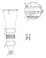
- Fig. 1-A shows a schematic view of a liquid crystal projection display apparatus in an embodiment of the present invention, in which the part 1 is a light source for generating divergent light, 2 is a condenser lens for converting the divergent rays from the light source 1 into parallel rays, 3 is a liquid crystal display device, 4 is a projection lens, and 5 is a screen.
- Fig. 1-B is a partial enlarged view of the liquid crystal display device 3, which is a plan view of the substrate having formed thereon switching elements 11.
- the part 11 is a switching element for transmitting a signal to a liquid crystal pixel electrode to cause optical modulation.
- the symbol + shows the center of the opening of each pixel.
- the part 12 is a pixel, which is constituted by a transparent electrode.
- Fig. 1-C shows a partially enlarged section of the liquid crystal display device 3, which is constituted by a polarizer 6, a first microlens array 7, a liquid crystal display panel 8, a second microlens array 9, and a polarizer 10.
- the liquid crystal display panel 8 is so constituted that a liquid crystal is sandwiched between a substrate having formed thereon switching elements 11 and pixel electrodes in a matrix form and a substrate having formed thereon a common electrode.
- Each of the first and second microlens arrays 7 and 9 is formed by arranging the same microlenses having positive refractive power in a matrix form, so that the optical axes of the microlenses agree with the centers + of the openings of the corresponding pixels of the liquid crystal display panel 8.
- the light incident on the liquid crystal display device 3 is linearly polarized with the polarizer 6, after which it is finely divided into each of the matrix form pixels of the liquid crystal display panel 8, condensed and taken into the liquid crystal pixels.
- the light coming into the liquid crystal display panel 8 is once condensed, and then diverged from the vicinity of the center of the opening of the pixel 12, and, of the finely divided lights, only the light subjected to optical modulation by the liquid crystal pixels pass through the polarizer 10.
- the divergent light which passed through the liquid crystal display panel 8 is converted to approximately parallel rays with the second microlens array, enlarged by the projection lens, and projected on the screen.
- the focal length of each microlens of the first and second microlens arrays 7 and 9 is designed to be a distance from the microlens face to the surface of the substrate including the switching elements 11 of the liquid crystal display panel 8 in, for example, the wavelength of green light (545 nm).
- the liquid crystal display panel 8 and the first and second microlens arrays 7 and 9 are coupled in the following manner.
- the liquid crystal display panel 8 and the second microlens array 9 are also formed in the similar manner.
- the microlens array may be a plane microlens array or a Fresnel lens array.
- the liquid crystal display panel and the microlens arrays are fixed together, the liquid crystal display panel 8 and the microlens arrays may not necessarily be fixed together but be position-adjustably coupled.
- Fig. 2 shows an example of the case of coupling without fixing together.
- the part 21 is a fine adjustment knob in the x coordinate direction
- 22 is a fine adjustment knob in the y co-ordinate direction
- 23 is a fine adjustment knob in the z co-ordinate direction.
- corrections of x and y co-ordinates can be easily done with the fine adjustment knobs 21 and 22 in case of the dislocation of the position.
- liquid crystal display panel and the first and second microlens arrays 7 and 9 are both adjustably coupled, in case of the dislocation of position, correction is easy and there is no necessity to pay attention to she kind of the substrate. However, surface reflections may occur on the liquid crystal display element and the microlens, and the light amount may decrease.
- the liquid crystal display panel is fixed to the first microlens array 7 and adjustably coupled to the second microlens array 9, or where the liquid crystal display panel is adjustably coupled to the first microlens array 7 and fixed to the second microlens array 9, these assemblies possess merits and demerits of half those of the abovementioned cases, respectively.
- liquid crystal display panel is adjustably coupled to the first microlens array 7 and fixed to the second microlens array 9 is systematically easy, and is considered to have better systematic effect than the case where the first and the second microlens arrays 7 and 9 are both fixed. Further, with respect to the relation of the liquid crystal display panel to the first microlens array 7, the precision of position setting is optically strict, and with the second microlens array 9, the precision of position setting is relatively mild, but it is not desired to reduce the light amount. An appropriate coupling method may be selected in consideration of the conditions for these two cases.
Landscapes
- Physics & Mathematics (AREA)
- Crystallography & Structural Chemistry (AREA)
- Nonlinear Science (AREA)
- Chemical & Material Sciences (AREA)
- Mathematical Physics (AREA)
- Signal Processing (AREA)
- Multimedia (AREA)
- Engineering & Computer Science (AREA)
- General Physics & Mathematics (AREA)
- Optics & Photonics (AREA)
- Liquid Crystal (AREA)
- Projection Apparatus (AREA)
- Devices For Indicating Variable Information By Combining Individual Elements (AREA)
Applications Claiming Priority (2)
| Application Number | Priority Date | Filing Date | Title |
|---|---|---|---|
| JP1280549A JPH03140920A (ja) | 1989-10-26 | 1989-10-26 | 投写型表示装置及び該投写型表示装置に用いる液晶表示装置 |
| JP280549/89 | 1989-10-26 |
Publications (2)
| Publication Number | Publication Date |
|---|---|
| EP0425266A2 true EP0425266A2 (fr) | 1991-05-02 |
| EP0425266A3 EP0425266A3 (en) | 1991-12-27 |
Family
ID=17626607
Family Applications (1)
| Application Number | Title | Priority Date | Filing Date |
|---|---|---|---|
| EP19900311646 Withdrawn EP0425266A3 (en) | 1989-10-26 | 1990-10-24 | Liquid crystal projection display apparatus |
Country Status (3)
| Country | Link |
|---|---|
| US (1) | US5126863A (fr) |
| EP (1) | EP0425266A3 (fr) |
| JP (1) | JPH03140920A (fr) |
Cited By (6)
| Publication number | Priority date | Publication date | Assignee | Title |
|---|---|---|---|---|
| EP0598608A1 (fr) * | 1992-11-17 | 1994-05-25 | Sharp Kabushiki Kaisha | Dispositif d'affichage à vue directe |
| GB2279171A (en) * | 1993-06-16 | 1994-12-21 | Samsung Aerospace Ind | Liquid crystal display |
| US5392140A (en) * | 1992-05-15 | 1995-02-21 | Sharp Kabushiki Kaisha | Optical device with two lens arrays with the second array pitch an integral multiple of the first array pitch |
| US5499138A (en) * | 1992-05-26 | 1996-03-12 | Olympus Optical Co., Ltd. | Image display apparatus |
| GB2315356A (en) * | 1996-07-15 | 1998-01-28 | Lg Electronics Inc | Liquid crystal display with microlenses |
| WO2003005733A1 (fr) * | 2001-07-06 | 2003-01-16 | Explay Ltd. | Dispositif et procede de projection d'images |
Families Citing this family (32)
| Publication number | Priority date | Publication date | Assignee | Title |
|---|---|---|---|---|
| US5666175A (en) * | 1990-12-31 | 1997-09-09 | Kopin Corporation | Optical systems for displays |
| JP3213977B2 (ja) * | 1991-08-23 | 2001-10-02 | ソニー株式会社 | 液晶表示装置及びその製造方法 |
| JPH06102509A (ja) * | 1992-06-17 | 1994-04-15 | Xerox Corp | 光カップリング・レンズアレイ付きフルカラー表示装置 |
| KR100270618B1 (ko) * | 1992-06-30 | 2000-12-01 | 윤종용 | 다결정 실리콘 박막의 제조방법 |
| JPH0610927U (ja) * | 1992-07-10 | 1994-02-10 | シャープ株式会社 | 液晶表示装置 |
| US5689315A (en) * | 1992-07-15 | 1997-11-18 | Matsushita Electric Industrial Co., Ltd. | Light valve apparatus which is employed in a projection display system and in a view-finder system |
| JPH06202096A (ja) * | 1992-12-28 | 1994-07-22 | Sony Corp | 映像プロジェクタ装置 |
| JPH06258637A (ja) * | 1993-03-04 | 1994-09-16 | Sony Corp | 液晶表示装置 |
| US5608551A (en) * | 1993-04-12 | 1997-03-04 | In Focus Systems, Inc. | Display panel assembly with microlens structure |
| US5439621A (en) * | 1993-04-12 | 1995-08-08 | Minnesota Mining And Manufacturing Company | Method of making an array of variable focal length microlenses |
| US5398125A (en) * | 1993-11-10 | 1995-03-14 | Minnesota Mining And Manufacturing Company | Liquid crystal projection panel having microlens arrays, on each side of the liquid crystal, with a focus beyond the liquid crystal |
| GB9420750D0 (en) * | 1994-10-14 | 1994-11-30 | Philips Electronics Uk Ltd | Colour liquid crystal projection display systems |
| US5606436A (en) * | 1994-11-21 | 1997-02-25 | Proxima Corporation | Liquid crystal projection panel construction and method of making same |
| US5652661A (en) * | 1995-06-07 | 1997-07-29 | Eastman Kodak Company | High speed photographic printer using optical and digital printing with an active matrix LCD |
| JP3195238B2 (ja) * | 1996-06-18 | 2001-08-06 | シャープ株式会社 | 投影型カラー液晶表示装置 |
| US5743615A (en) * | 1996-12-31 | 1998-04-28 | Eastman Kodak Company | Film slides having encoded data and methods for preparing film slides |
| US5803565A (en) * | 1996-12-31 | 1998-09-08 | Eastman Kodak Company | Orienting projector |
| US5743609A (en) * | 1996-12-31 | 1998-04-28 | Eastman Kodak Company | Method and apparatus for preparing photographic film units having image frame associated encoded information |
| US5751399A (en) * | 1996-12-31 | 1998-05-12 | Eastman Kodak Company | Film slides having data windows |
| US6079832A (en) * | 1996-12-31 | 2000-06-27 | Eastman Kodak Company | Annotation displaying projector |
| US5738428A (en) * | 1996-12-31 | 1998-04-14 | Eastman Kodak Company | Formatting projector |
| US5990992A (en) * | 1997-03-18 | 1999-11-23 | Nippon Sheet Glass Co., Ltd. | Image display device with plural planar microlens arrays |
| US5944404A (en) * | 1997-07-18 | 1999-08-31 | Eastman Kodak Company | Defined orientation slide projector and slides |
| WO1999024852A1 (fr) * | 1997-10-16 | 1999-05-20 | Matsushita Electric Industrial Co., Ltd. | Dispositif de separation de la polarisation d'elements d'hologramme, dispositif d'eclairage par polarisation et affichage d'image |
| CN1209667C (zh) * | 2000-05-22 | 2005-07-06 | 日本化药株式会社 | 改善液晶投影机对比度的方法 |
| JP4541708B2 (ja) * | 2002-03-05 | 2010-09-08 | コーニング インコーポレイテッド | 光学部材および光学部材と光学系の性能を予測する方法 |
| AU2003220148A1 (en) * | 2002-03-14 | 2003-09-29 | Corning Incorporated | Fiber array and methods of fabrication |
| US20070047043A1 (en) * | 2002-07-08 | 2007-03-01 | Explay Ltd. | image projecting device and method |
| CN1688516A (zh) * | 2002-10-04 | 2005-10-26 | 康宁股份有限公司 | 透镜阵列及制造这种透镜阵列和光敏玻璃板的方法 |
| US20070040970A1 (en) * | 2002-11-12 | 2007-02-22 | Kenichiro Yoshioka | Contrast ratio improving method for liquid crystal projector |
| JP2010107721A (ja) * | 2008-10-30 | 2010-05-13 | Hitachi Displays Ltd | 液晶表示装置 |
| JP5924244B2 (ja) * | 2012-11-21 | 2016-05-25 | ソニー株式会社 | 液晶表示装置および投射型表示装置 |
Family Cites Families (11)
| Publication number | Priority date | Publication date | Assignee | Title |
|---|---|---|---|---|
| US4134651A (en) * | 1976-08-31 | 1979-01-16 | The Monotype Corporation Limited | Method of making an assembly |
| JPS60165622A (ja) * | 1984-02-08 | 1985-08-28 | Nec Corp | 透過型表示素子 |
| JPS60262131A (ja) * | 1984-06-08 | 1985-12-25 | Sharp Corp | 液晶表示装置 |
| JPH0535388Y2 (fr) * | 1985-07-29 | 1993-09-08 | ||
| JPS6344624A (ja) * | 1986-08-12 | 1988-02-25 | Fuji Photo Film Co Ltd | 液晶デバイス |
| JPS63124028A (ja) * | 1986-11-13 | 1988-05-27 | Fuji Photo Film Co Ltd | 液晶シヤツタアレイ |
| EP0287034B1 (fr) * | 1987-04-14 | 1995-01-18 | Seiko Epson Corporation | Dispositif d'affichage à cristal liquide en couleurs par projection |
| JPH01187502A (ja) * | 1988-01-22 | 1989-07-26 | Seiko Epson Corp | 平板レンズアレイ及び平板レンズアレイを備えた液晶表示素子 |
| JPH01189685A (ja) * | 1988-01-26 | 1989-07-28 | Seiko Epson Corp | 液晶ライトバルブ及び液晶ライトバルブを備えたビデオプロジェクター |
| JPH0769532B2 (ja) * | 1988-06-11 | 1995-07-31 | シャープ株式会社 | 投影型表示装置 |
| JPH0642126B2 (ja) * | 1988-10-26 | 1994-06-01 | シャープ株式会社 | 投影型画像表示装置 |
-
1989
- 1989-10-26 JP JP1280549A patent/JPH03140920A/ja active Pending
-
1990
- 1990-10-23 US US07/600,986 patent/US5126863A/en not_active Expired - Lifetime
- 1990-10-24 EP EP19900311646 patent/EP0425266A3/en not_active Withdrawn
Cited By (13)
| Publication number | Priority date | Publication date | Assignee | Title |
|---|---|---|---|---|
| US5392140A (en) * | 1992-05-15 | 1995-02-21 | Sharp Kabushiki Kaisha | Optical device with two lens arrays with the second array pitch an integral multiple of the first array pitch |
| US5499138A (en) * | 1992-05-26 | 1996-03-12 | Olympus Optical Co., Ltd. | Image display apparatus |
| EP0598608A1 (fr) * | 1992-11-17 | 1994-05-25 | Sharp Kabushiki Kaisha | Dispositif d'affichage à vue directe |
| US5561538A (en) * | 1992-11-17 | 1996-10-01 | Sharp Kabushiki Kaisha | Direct-view display apparatus |
| GB2279171A (en) * | 1993-06-16 | 1994-12-21 | Samsung Aerospace Ind | Liquid crystal display |
| GB2315356B (en) * | 1996-07-15 | 1999-07-21 | Lg Electronics Inc | Liquid crystal display with microlenses |
| GB2315356A (en) * | 1996-07-15 | 1998-01-28 | Lg Electronics Inc | Liquid crystal display with microlenses |
| US9857621B1 (en) | 1996-07-15 | 2018-01-02 | Lg Display Co., Ltd. | Display device |
| US10768472B2 (en) | 1996-07-15 | 2020-09-08 | Lg Display Co., Ltd. | Display device |
| US11156866B2 (en) | 1996-07-15 | 2021-10-26 | Lg Display Co., Ltd. | Display device |
| WO2003005733A1 (fr) * | 2001-07-06 | 2003-01-16 | Explay Ltd. | Dispositif et procede de projection d'images |
| US7128420B2 (en) | 2001-07-06 | 2006-10-31 | Explay Ltd. | Image projecting device and method |
| CN1298175C (zh) * | 2001-07-06 | 2007-01-31 | 以克斯普雷有限公司 | 图像投影装置和方法 |
Also Published As
| Publication number | Publication date |
|---|---|
| US5126863A (en) | 1992-06-30 |
| EP0425266A3 (en) | 1991-12-27 |
| JPH03140920A (ja) | 1991-06-14 |
Similar Documents
| Publication | Publication Date | Title |
|---|---|---|
| US5126863A (en) | Liquid crystal projection display apparatus having two microlens arrays | |
| US6345895B1 (en) | Projection type display apparatus | |
| US5353133A (en) | A display having a standard or reversed schieren microprojector at each picture element | |
| US5684548A (en) | Liquid crystal display element and micro-lens arrangement and a display using the same | |
| EP0337555A1 (fr) | Dispositif d'affichage | |
| US6680762B2 (en) | Projection liquid crystal display apparatus wherein overall focal point of the lens is shifted to increase effective aperture ratio | |
| US5764323A (en) | Transmission type display device with aspheric microlenses | |
| KR100231979B1 (ko) | 표시장치, 액정표시패널 및 이를 사용한 투사형 표시장치 | |
| JP2714939B2 (ja) | 投写型カラー表示装置 | |
| US5430562A (en) | Liquid crystal light valve including between light and light valve microlenses and two reflecting layers with a matrix of openings | |
| KR19990068015A (ko) | 액정 영사기 | |
| JPH03175436A (ja) | カラー画像投写装置と、その液晶表示装置 | |
| JP2000075259A (ja) | 液晶装置及びこれを用いた投写型表示装置 | |
| JP3746905B2 (ja) | 画像プロジェクタ | |
| KR970000348B1 (ko) | 액정투영기용 액정패널 | |
| JP3228896B2 (ja) | 反射型lcdパネルユニット及びこれを用いた液晶プロジェクター | |
| KR19980036963A (ko) | 엘시디 프로젝터의 엘시디 위치 제어 장치 | |
| JPH0430140A (ja) | 投影型カラー液晶表示装置 | |
| JPH07199188A (ja) | 液晶表示素子と液晶表示素子を用いた液晶表示装置 | |
| EP0746163A1 (fr) | Dispositif d'affichage d'image en couleur par projection | |
| JP2982990B2 (ja) | 表示装置及び光学ユニット | |
| JPH09114023A (ja) | 投影型カラー画像表示装置 | |
| JPH0255384A (ja) | 投写型表示装置 | |
| JPH0361927A (ja) | 液晶表示装置 | |
| JPH06308492A (ja) | 投写型カラー液晶表示装置 |
Legal Events
| Date | Code | Title | Description |
|---|---|---|---|
| PUAI | Public reference made under article 153(3) epc to a published international application that has entered the european phase |
Free format text: ORIGINAL CODE: 0009012 |
|
| AK | Designated contracting states |
Kind code of ref document: A2 Designated state(s): DE FR GB NL |
|
| PUAL | Search report despatched |
Free format text: ORIGINAL CODE: 0009013 |
|
| AK | Designated contracting states |
Kind code of ref document: A3 Designated state(s): DE FR GB NL |
|
| STAA | Information on the status of an ep patent application or granted ep patent |
Free format text: STATUS: THE APPLICATION IS DEEMED TO BE WITHDRAWN |
|
| 18D | Application deemed to be withdrawn |
Effective date: 19920630 |