EP0425287B1 - Bildaufzeichnungsverfahren und Filmstruktur dafür - Google Patents
Bildaufzeichnungsverfahren und Filmstruktur dafür Download PDFInfo
- Publication number
- EP0425287B1 EP0425287B1 EP90311700A EP90311700A EP0425287B1 EP 0425287 B1 EP0425287 B1 EP 0425287B1 EP 90311700 A EP90311700 A EP 90311700A EP 90311700 A EP90311700 A EP 90311700A EP 0425287 B1 EP0425287 B1 EP 0425287B1
- Authority
- EP
- European Patent Office
- Prior art keywords
- film
- image
- films
- anisotropy
- polarising
- Prior art date
- Legal status (The legal status is an assumption and is not a legal conclusion. Google has not performed a legal analysis and makes no representation as to the accuracy of the status listed.)
- Expired - Lifetime
Links
Images


Classifications
-
- G—PHYSICS
- G03—PHOTOGRAPHY; CINEMATOGRAPHY; ANALOGOUS TECHNIQUES USING WAVES OTHER THAN OPTICAL WAVES; ELECTROGRAPHY; HOLOGRAPHY
- G03F—PHOTOMECHANICAL PRODUCTION OF TEXTURED OR PATTERNED SURFACES, e.g. FOR PRINTING, FOR PROCESSING OF SEMICONDUCTOR DEVICES; MATERIALS THEREFOR; ORIGINALS THEREFOR; APPARATUS SPECIALLY ADAPTED THEREFOR
- G03F7/00—Photomechanical, e.g. photolithographic, production of textured or patterned surfaces, e.g. printing surfaces; Materials therefor, e.g. comprising photoresists; Apparatus specially adapted therefor
- G03F7/20—Exposure; Apparatus therefor
- G03F7/2002—Exposure; Apparatus therefor with visible light or UV light, through an original having an opaque pattern on a transparent support, e.g. film printing, projection printing; by reflection of visible or UV light from an original such as a printed image
- G03F7/2004—Exposure; Apparatus therefor with visible light or UV light, through an original having an opaque pattern on a transparent support, e.g. film printing, projection printing; by reflection of visible or UV light from an original such as a printed image characterised by the use of a particular light source, e.g. fluorescent lamps or deep UV light
- G03F7/2006—Exposure; Apparatus therefor with visible light or UV light, through an original having an opaque pattern on a transparent support, e.g. film printing, projection printing; by reflection of visible or UV light from an original such as a printed image characterised by the use of a particular light source, e.g. fluorescent lamps or deep UV light using coherent light; using polarised light
-
- G—PHYSICS
- G03—PHOTOGRAPHY; CINEMATOGRAPHY; ANALOGOUS TECHNIQUES USING WAVES OTHER THAN OPTICAL WAVES; ELECTROGRAPHY; HOLOGRAPHY
- G03C—PHOTOSENSITIVE MATERIALS FOR PHOTOGRAPHIC PURPOSES; PHOTOGRAPHIC PROCESSES, e.g. CINE, X-RAY, COLOUR, STEREO-PHOTOGRAPHIC PROCESSES; AUXILIARY PROCESSES IN PHOTOGRAPHY
- G03C1/00—Photosensitive materials
- G03C1/72—Photosensitive compositions not covered by the groups G03C1/005 - G03C1/705
- G03C1/73—Photosensitive compositions not covered by the groups G03C1/005 - G03C1/705 containing organic compounds
- G03C1/733—Photosensitive compositions not covered by the groups G03C1/005 - G03C1/705 containing organic compounds with macromolecular compounds as photosensitive substances, e.g. photochromic
-
- Y—GENERAL TAGGING OF NEW TECHNOLOGICAL DEVELOPMENTS; GENERAL TAGGING OF CROSS-SECTIONAL TECHNOLOGIES SPANNING OVER SEVERAL SECTIONS OF THE IPC; TECHNICAL SUBJECTS COVERED BY FORMER USPC CROSS-REFERENCE ART COLLECTIONS [XRACs] AND DIGESTS
- Y10—TECHNICAL SUBJECTS COVERED BY FORMER USPC
- Y10S—TECHNICAL SUBJECTS COVERED BY FORMER USPC CROSS-REFERENCE ART COLLECTIONS [XRACs] AND DIGESTS
- Y10S430/00—Radiation imagery chemistry: process, composition, or product thereof
- Y10S430/165—Thermal imaging composition
Definitions
- the present invention relates to a process for recording an image and a film structure therefor.
- the present invention provides a new process for recording an image by using the above phenomenon.
- the process comprises
- the present invention also provides a film structure for recording an image, comprising two polarising films whose polarisation directions are parallel or mutually orthogonal and, sandwiched therebetween, an anisotropic molecular oriented film whose anisotropy is at an angle of 45 ⁇ 10° with respect to the polarisation directions of the polarising films, the film structure having also an image portion whose molecular orientation anisotropy is degraded completely or incompletely by heat or light.
- one of the polarising films may be substituted by a reflective film.
- Fig. 1 is a schematic drawing which explains the theoretical principle behind the present invention.
- Fig. 2 is a drawing which explains the image recording process of the present invention.
- Fig. 3 shows front and side views of one embodiment of apparatus that can be used in the present invention.
- Fig. 4 is a schematic sectional view of a positive or negative film.
- Fig. 5 shows schematically the conversion system of positive and negative.
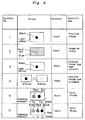
- Fig. 6 shows the results of Examples.
- the polarizing film employed in the present invention is not limited, but preferred are those having good physical stabilities, such as heat resistance, weather resistance, water resistance and also having good polarizing degree.
- the polarizing film may be commercially available, including KAYAPOLAR KPL-23 and NITTO T-1205.
- the anisotropic molecular oriented film of the present invention is a polymer film which is uniaxially or biaxially oriented 1.5 to 6 times to align the axes of polymer molecules parallel to the polymer film surface.
- the polymer films are polyvinyl chloride, polymethyl methacrylate, polystyrene, polyethylene, polypropylene, polyethylene terephthalate, polyamide, polyvinyl alcohol and the like.
- an additive such as, a plasticizer and a dye stuff
- the anisotropic molecular oriented polymer film may be composed of one layer or more than one layers.
- the plural layers may be prepared either from same polymer materials which have different stretch percents, or from the different polymer materials.
- the polymer film may be prepared from a photodegradative polymer, which is exposed to light and then subjected to heat to degrade the anisotropy of the molecular orientation.
- the polymer film may also be prepared from a light-isomerizable polymer. The isomerization reaction makes it possible to reversibly convert the degradation of the anisotropy of the molecular orientation, whereby a formation and an elimination of images can be reversibly conducted. Examples of the light-isomerizable polymers are reported in detail in "Lectures of Chemical Fibers" by Eiichi Kobayashi et al., vol. 44, page 95 (1987).
- the two polarizing films are arranged as the polarization directions are parallel or perpendicular to each other and the anisotropic molecular oriented film is inserted therebetween as an angle of the axes of the molecular orientation and the polarization directions is about 45 °.
- angles including parallel and perpendicular are not defined strictly, so that an angle of 45 ° for example, is understood as having a breadth of about ⁇ 10 °.
- the two polarizing films are generally employed, but one of the polarizing films may be changed to a reflective film (or plate) so as to perform the same function of the present invention.
- the reflective film (or plate) includes a mirror, a metal (e.g. aluminum)-deposited film and the like.
- the anisotropic molecular oriented film of the present invention has an image portion of which the anisotropy of the molecular orientation is degraded by heat or light.
- the degradation of the anisotropy is conducted completely or incompletely. If the degradation is conducted incompletely, the image portion may be colored because some degree of the anisotropy of the molecular orientation is left. If the degradation is completely conducted, the image portion is either colorless or black according to the angle (i.e. parallel or perpendicular) of the polarization directions of the two polarizing films.
- the degradation by heat is generally carried out by exposing the image portion of the film to a heat-mode laser or a heat head. If it is conducted by light, preferred are a digital recording process using laser beam, an analog recording process using a mercury lamp and the like. If the anisotropic film has more than one layers, the degradation can be carried out gradually and therefore it is easy to control color.
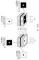
- Figs.2 (a), (b) and (c) schematically show sectional views of the film structure of the-present invention and Figs.2 (d) and (e) show plane views of the structure of the present invention.
- the anisotropic molecular oriented film 2 is inserted between the two polarizing films 1 and 3.
- the anisotropy of molecular orientation is degraded by heat or light as shown in Fig.2 (b) and the degraded portion does not permit light to get through and develops a black image, as shown in Figs.2 (c) and (e), thus finishing the recording process.
- Fig. 3 shows a front view and a side view of the apparatus.
- Fig. 3 shows a light source 11 and a cover 12 which is in contact with a combination of an anisotropic molecular oriented film having an image portion and another polarising film under vacuum.
- a support body 13 includes a vacuum pump, a light controlling device and the like. The light source 11 and the support body 13 are no different from those in a conventional printing apparatus, but the cover 12 is a polarising film in the present invention.
- Fig. 4 schematically shows a sectional view of the cover 12 and the above-mentioned film combination.
- Fig. 4 shows the support 13, and a frame 14 for the cover 12. Between the cover 12 and the support 13, the anisotropic molecular oriented film 15, the other polarising film 16 and a photosensitive printing plate 17 are sandwiched.
- the cover 12 is a polarising film and is adapted for removal, so that the conversion of positive and negative is very easily conducted by changing the direction of polarisation of the cover 12.
- the conversion system is clearly understood from Fig. 5.
- the conversion may be conducted by changing the polarizing direction of the other polarizing film 16.
- the conversion of a positive image and a negative image is very easily conducted by changing an angle of the polarizing axes of the two polarizing films.
- the polarizing film and the anisotropic molecular oriented film are both commercially available as industrial products and therefore cheap enough to reduce the producing cost.
- the films are obtainable in a large area and the obtained image is also made large area. Since the process of the present invention does not use a liquid developer and does not have developing and fixing steps, a very simplified process is performed. Also, the process is based on physical image formation and therefore different from a conventional process which employs much chemical reactions. Color selection is also conducted by controlling a heat or light exposure amount without color dyestuffs. Further, a color contrast of white and black is high sufficient to apply photosensitive printing plates and the others.
- the conversion of negative and positive can be easily and simply conducted.
- a uniaxially oriented polyethylene film was inserted between two polarizing films which were perpendicular and laminated by an adhesive to form a film structure having light yellow color.
- the structure was exposed to a semiconductor laser as shown in Fig.2.
- the conditions of the images are shown in Fig.6.
- a film structure was obtained as generally described in Example 1, with the exception that the two polarizing films were set parallel instead.
- the obtained film showed dark blue.
- the structure was exposed to a semiconductor laser as shown in Fig. 2.
- the conditions of the images are shown in Fig. 6.
- a uniaxially oriented light-degradation film (polyvinyl chloride which was treated with hexachloroacetone) was inserted between two polarizing films which were perpendicular and laminated by an adhesive to form a film structure having light yellow color.
- the structure was exposed to a UV laser as shown in Fig.2 and heated at 100 °C. The conditions of the images are shown in Fig.6.
- the structure was exposed to a light having 527 nm and then exposed to a light having 546 nm.
- the conditions of the images are shown in Fig.6.
- a uniaxially oriented polyvinyl alcohol film was inserted between two polarizing films which were parallel and laminated by an adhesive to form a film structure having green color.
- the structure was exposed to a semiconductor laser as shown in Fig. 2, but an exposing time was reduced to about 1/2 of Example 1. Then another portion of the structure was exposed to the laser, but an exposing time was reduced to about 1/3 of Example 1.
- the conditions of the images are shown in Fig.6.
- a biaxially oriented polyethylene film was adhered on a biaxially oriented polypropylene film and then inserted between two polarizing films which were perpendicular.
- the three films were laminated by an adhesive to form a film structure having red color.
- the structure was exposed to a semiconductor laser as shown in Fig.2, but an exposing time was changed to two times and three times of Example 1. The conditions of the images are shown in Fig.6.
Landscapes
- Physics & Mathematics (AREA)
- General Physics & Mathematics (AREA)
- Spectroscopy & Molecular Physics (AREA)
- Chemical & Material Sciences (AREA)
- Engineering & Computer Science (AREA)
- Materials Engineering (AREA)
- Thermal Transfer Or Thermal Recording In General (AREA)
- Polarising Elements (AREA)
Claims (4)
- Verfahren zur Aufzeichnung eines Bildes, wobei man(i) einen anisotropen molekular orientierten Film (2) zwischen zwei polarisierende Filme (1, 3) einlegt, deren Polarisationsrichtungen parallel oder senkrecht zueinander sind, wobei die Anisotropie des orientierten Films in einem Winkel von 45 ± 10° bezüglich der Polarisationsrichtungen der polarisierenden Filme liegt, und man(ii) die Anisotropie eines Bildteilbereichs im orientierten Film vollständig oder unvollständig abbaut.
- Verfahren gemäß Anspruch 1, worin ein reflektierender Film anstatt einem der polarisierenden Filme verwendet wird.
- Filmstruktur zur Aufzeichnung eines Bildes, umfassend zwei polarisierende Filme (1, 3), deren Polarisationsrichtungen parallel oder senkrecht zueinander sind, sowie, sandwichartig dazwischen angeordnet, einen anisotropen molekular orientierten Film (2), dessen Anisotropie in einem Winkel von 45 ± 10° bezüglich der Polarisationsrichtungen der polarisierenden Filme liegt, wobei die Filmstruktur auch einen Bildteilbereich aufweist, dessen molekulare Orientationsanisotropie vollständig oder unvollständig durch Hitze- oder Lichteinwirkung abgebaut ist.
- Laminierte Filmstruktur gemäß Anspruch 3, worin ein reflektierender Film einen der polarisierenden Filme ersetzt.
Applications Claiming Priority (4)
| Application Number | Priority Date | Filing Date | Title |
|---|---|---|---|
| JP28060389A JP2922937B2 (ja) | 1989-10-27 | 1989-10-27 | 画像記録方法およびそれに用いる積層フィルム |
| JP280603/89 | 1989-10-27 | ||
| JP79952/90 | 1990-07-26 | ||
| JP7995290U JP2531838Y2 (ja) | 1990-07-26 | 1990-07-26 | 印刷製版用焼付装置 |
Publications (3)
| Publication Number | Publication Date |
|---|---|
| EP0425287A2 EP0425287A2 (de) | 1991-05-02 |
| EP0425287A3 EP0425287A3 (en) | 1992-02-12 |
| EP0425287B1 true EP0425287B1 (de) | 1995-09-20 |
Family
ID=26420933
Family Applications (1)
| Application Number | Title | Priority Date | Filing Date |
|---|---|---|---|
| EP90311700A Expired - Lifetime EP0425287B1 (de) | 1989-10-27 | 1990-10-25 | Bildaufzeichnungsverfahren und Filmstruktur dafür |
Country Status (4)
| Country | Link |
|---|---|
| US (1) | US5049927A (de) |
| EP (1) | EP0425287B1 (de) |
| CA (1) | CA2028672A1 (de) |
| DE (1) | DE69022532T2 (de) |
Families Citing this family (7)
| Publication number | Priority date | Publication date | Assignee | Title |
|---|---|---|---|---|
| US5900974A (en) * | 1997-02-05 | 1999-05-04 | Micron Technology, Inc. | Backing plate for contrast enhancement of photolithographic images on transparent substrates and method of using same |
| US20040202445A1 (en) * | 2003-03-20 | 2004-10-14 | Pixar | Component color flat panel digital film recorder and method |
| US7787010B2 (en) * | 2003-03-20 | 2010-08-31 | Pixar | Video to film flat panel digital recorder and method |
| US7463821B2 (en) * | 2003-03-20 | 2008-12-09 | Pixar | Flat panel image to film transfer method and apparatus |
| US7576830B2 (en) * | 2003-03-20 | 2009-08-18 | Pixar | Configurable flat panel image to film transfer method and apparatus |
| US20040184762A1 (en) * | 2003-03-20 | 2004-09-23 | Pixar | Flat panel digital film recorder and method |
| KR101417250B1 (ko) * | 2012-02-20 | 2014-07-08 | (주)엘지하우시스 | 고내열성 다층 광학필름 및 그의 제조방법 |
Family Cites Families (7)
| Publication number | Priority date | Publication date | Assignee | Title |
|---|---|---|---|---|
| JPS5647535B2 (de) * | 1973-07-30 | 1981-11-10 | ||
| CA1036699A (en) * | 1974-02-28 | 1978-08-15 | Akio Moriyama | Electro-optical display device |
| DE2820965A1 (de) * | 1978-05-12 | 1979-11-15 | Agfa Gevaert Ag | Fotografisches kopiergeraet |
| DE3140078A1 (de) * | 1980-10-08 | 1982-04-22 | Kabushiki Kaisha Suwa Seikosha, Tokyo | Optische fluessigkristalleinrichtung und drucker, der eine solche optische einrichtung als lichtventil benutzt |
| JPS58114978A (ja) * | 1981-12-28 | 1983-07-08 | Seiko Epson Corp | 液晶光学的印写装置 |
| JPS60227235A (ja) * | 1984-04-26 | 1985-11-12 | Canon Inc | 画像形成装置 |
| US4784476A (en) * | 1987-01-27 | 1988-11-15 | Hughes Aircraft Company | Nipi refractive index modulation apparatus and method |
-
1990
- 1990-10-25 EP EP90311700A patent/EP0425287B1/de not_active Expired - Lifetime
- 1990-10-25 DE DE69022532T patent/DE69022532T2/de not_active Expired - Fee Related
- 1990-10-26 CA CA002028672A patent/CA2028672A1/en not_active Abandoned
- 1990-10-29 US US07/603,841 patent/US5049927A/en not_active Expired - Lifetime
Also Published As
| Publication number | Publication date |
|---|---|
| EP0425287A3 (en) | 1992-02-12 |
| CA2028672A1 (en) | 1991-04-28 |
| DE69022532T2 (de) | 1996-03-14 |
| EP0425287A2 (de) | 1991-05-02 |
| DE69022532D1 (de) | 1995-10-26 |
| US5049927A (en) | 1991-09-17 |
Similar Documents
| Publication | Publication Date | Title |
|---|---|---|
| US4743092A (en) | Polarizing grids for far-infrared and method for making same | |
| US6384971B1 (en) | Methods for manufacturing micropolarizers | |
| US4610509A (en) | Liquid crystal color display panels | |
| EP0827600B1 (de) | Verfahren zur herstellung einer flüssigkristall-anzeige | |
| US4987043A (en) | Method for the production of a multicolor filter array | |
| US7414782B2 (en) | Polarized stereoscopic display apparatus and manufacturing method thereof | |
| US5235449A (en) | Polarizer with patterned diacetylene layer, method for producing the same, and liquid crystal display device including such polarizer | |
| EP0670506A1 (de) | Polarisator,polarisationsplatte und verfahren zu deren herstellung | |
| HK1010800A1 (en) | Liquid crystal cell | |
| US20010040730A1 (en) | Micro-retarder plate | |
| US20030137626A1 (en) | Method of making a passive patterned retarder and retarder made by such a method | |
| CA2038869A1 (en) | Optical modulation device and display apparatus | |
| EP0516479A2 (de) | Flüssigkristall-Projektionsanzeigevorrichtung | |
| US5049927A (en) | Process for recording an image, a film structure therefor and its applications | |
| JP2922937B2 (ja) | 画像記録方法およびそれに用いる積層フィルム | |
| US3015989A (en) | Light-polarizing film materials and process of preparation | |
| EP0444703B1 (de) | Polarisatoren, Verfahren zu ihrer Herstellung und Flüssigkristall-Anzeigevorrichtungen | |
| JPS58125002A (ja) | 偏光板及び液晶表示素子 | |
| JP2516087B2 (ja) | 製版装置 | |
| US2868077A (en) | Film stock for dichroic dye images | |
| JPS61103119A (ja) | 立体画用偏光板の製造法 | |
| GB2171533A (en) | Liquid crystal light shutter | |
| JP2741111B2 (ja) | カラーフイルターの作成方法 | |
| EP1012640A1 (de) | Vorrichtung zur unterdrückung des strahls nullter ordnung von einem mit polarisiertem licht beleuchteten hologramms | |
| KR100432993B1 (ko) | 칼라필터를채용한액정표시소자및그칼라필터의제조방법 |
Legal Events
| Date | Code | Title | Description |
|---|---|---|---|
| PUAI | Public reference made under article 153(3) epc to a published international application that has entered the european phase |
Free format text: ORIGINAL CODE: 0009012 |
|
| AK | Designated contracting states |
Kind code of ref document: A2 Designated state(s): DE FR GB |
|
| PUAL | Search report despatched |
Free format text: ORIGINAL CODE: 0009013 |
|
| AK | Designated contracting states |
Kind code of ref document: A3 Designated state(s): DE FR GB |
|
| 17P | Request for examination filed |
Effective date: 19920723 |
|
| 17Q | First examination report despatched |
Effective date: 19940622 |
|
| GRAA | (expected) grant |
Free format text: ORIGINAL CODE: 0009210 |
|
| AK | Designated contracting states |
Kind code of ref document: B1 Designated state(s): DE FR GB |
|
| REF | Corresponds to: |
Ref document number: 69022532 Country of ref document: DE Date of ref document: 19951026 |
|
| ET | Fr: translation filed | ||
| PLBE | No opposition filed within time limit |
Free format text: ORIGINAL CODE: 0009261 |
|
| STAA | Information on the status of an ep patent application or granted ep patent |
Free format text: STATUS: NO OPPOSITION FILED WITHIN TIME LIMIT |
|
| 26N | No opposition filed | ||
| PGFP | Annual fee paid to national office [announced via postgrant information from national office to epo] |
Ref country code: FR Payment date: 19971009 Year of fee payment: 8 |
|
| PGFP | Annual fee paid to national office [announced via postgrant information from national office to epo] |
Ref country code: GB Payment date: 19971016 Year of fee payment: 8 |
|
| PGFP | Annual fee paid to national office [announced via postgrant information from national office to epo] |
Ref country code: DE Payment date: 19971031 Year of fee payment: 8 |
|
| PG25 | Lapsed in a contracting state [announced via postgrant information from national office to epo] |
Ref country code: GB Free format text: LAPSE BECAUSE OF NON-PAYMENT OF DUE FEES Effective date: 19981025 |
|
| GBPC | Gb: european patent ceased through non-payment of renewal fee |
Effective date: 19981025 |
|
| PG25 | Lapsed in a contracting state [announced via postgrant information from national office to epo] |
Ref country code: FR Free format text: LAPSE BECAUSE OF NON-PAYMENT OF DUE FEES Effective date: 19990630 |
|
| REG | Reference to a national code |
Ref country code: FR Ref legal event code: ST |
|
| PG25 | Lapsed in a contracting state [announced via postgrant information from national office to epo] |
Ref country code: DE Free format text: LAPSE BECAUSE OF NON-PAYMENT OF DUE FEES Effective date: 19990803 |