EP0425355A1 - Ortungssystem für einen beweglichen Körper - Google Patents
Ortungssystem für einen beweglichen Körper Download PDFInfo
- Publication number
- EP0425355A1 EP0425355A1 EP90402962A EP90402962A EP0425355A1 EP 0425355 A1 EP0425355 A1 EP 0425355A1 EP 90402962 A EP90402962 A EP 90402962A EP 90402962 A EP90402962 A EP 90402962A EP 0425355 A1 EP0425355 A1 EP 0425355A1
- Authority
- EP
- European Patent Office
- Prior art keywords
- time
- detector
- integration
- light
- photosensitive
- Prior art date
- Legal status (The legal status is an assumption and is not a legal conclusion. Google has not performed a legal analysis and makes no representation as to the accuracy of the status listed.)
- Granted
Links
Images



Classifications
-
- F—MECHANICAL ENGINEERING; LIGHTING; HEATING; WEAPONS; BLASTING
- F41—WEAPONS
- F41G—WEAPON SIGHTS; AIMING
- F41G7/00—Direction control systems for self-propelled missiles
- F41G7/20—Direction control systems for self-propelled missiles based on continuous observation of target position
- F41G7/30—Command link guidance systems
- F41G7/301—Details
- F41G7/303—Sighting or tracking devices especially provided for simultaneous observation of the target and of the missile
-
- G—PHYSICS
- G01—MEASURING; TESTING
- G01S—RADIO DIRECTION-FINDING; RADIO NAVIGATION; DETERMINING DISTANCE OR VELOCITY BY USE OF RADIO WAVES; LOCATING OR PRESENCE-DETECTING BY USE OF THE REFLECTION OR RERADIATION OF RADIO WAVES; ANALOGOUS ARRANGEMENTS USING OTHER WAVES
- G01S3/00—Direction-finders for determining the direction from which infrasonic, sonic, ultrasonic or electromagnetic waves, or particle emission, not having a directional significance, are being received
- G01S3/78—Direction-finders for determining the direction from which infrasonic, sonic, ultrasonic or electromagnetic waves, or particle emission, not having a directional significance, are being received using electromagnetic waves other than radio waves
- G01S3/782—Systems for determining direction or deviation from predetermined direction
- G01S3/783—Systems for determining direction or deviation from predetermined direction using amplitude comparison of signals derived from static detectors or detector systems
- G01S3/784—Systems for determining direction or deviation from predetermined direction using amplitude comparison of signals derived from static detectors or detector systems using a mosaic of detectors
Definitions
- the present invention relates to a system for locating a mobile. Although not exclusively, it is particularly suitable for locating and guiding missiles, for example anti-tank missiles.
- the position of the mobile relative to said axis is given by the position of the photosensitive element or elements of the matrix, excited by the image of the light flashes, relative to said axis.
- the optical transmitter generating light flashes and linked to the mobile can be a light beacon carried by the latter or else a simple mirror receiving light flashes from a fixed beacon and returning said fragments to the optical detector.
- the synchronization of the detector and the transmitter makes it possible to operate the said detector with a useful signal level close to the peak value of the power of the transmitter.
- the transmitter-detector link can therefore operate with a high signal / noise ratio, for a low average power, which makes it possible to limit the consumption and the cost of the transmitter.
- synchronization between the detector and the transmitter can be obtained by permanent connection means or else by temporary connection means, said detector and transmitter then comprising means (time bases). , to maintain said synchronization individually.
- synchronization can be ensured by an immaterial link or by a hardware link.
- the link is immaterial, of the radioelectric type, it is costly, since it is necessary to integrate appropriate equipment into the mobile; in addition, such a radio link is sensitive to interference and electromagnetic interference, which is a serious drawback, which could lead to the loss of the mobile by the optical detector.
- said link is hardware, it must have a high bandwidth in order to allow a high synchronization frequency.
- Such a hardware link can therefore only be constituted by an optical fiber, which gives the system a high cost. In any case, a hardware link necessarily limits the radius of action of the mobile in relation to the optical transmitter.
- synchronization it is often advantageous, and even sometimes compulsory, for synchronization to be obtained by means of time bases synchronized by a temporary link, prior to the launching of the mobile, one of said time bases being associated with the detector and the other to the transmitter.
- the object of the present invention is to remedy these drawbacks. It makes it possible to carry out the temporal tracking of the mobile, in a closed loop, without any link other than the optical link used for the location being established between the mobile and the location system. Thanks to the invention, it is the CCD matrix itself which makes it possible to permanently loop back the transmission-integration synchronization.
- the system for locating a mobile relative to an axis comprising: - an optical transmitter linked to said mobile and generating light flashes, depending on a first time base; and a photosensitive detector arranged at a fixed station and associated with an optical system observing the environment of said axis in which said mobile is capable of moving, said photosensitive detector comprising a matrix detector for charge transfer and for frame transfer controlled by means electronics associated with a second time base, and said matrix detector comprising a photosensitive zone on which said optical system is capable of forming the quasi-punctual image of said light flashes, the succession of integration times of the images in said photosensitive zone and transfer time of said images outside thereof being dependent on said second time base; said first and second time bases being temporarily synchronized before the launch of said mobile so that each of said light flashes occurs during an image integration time of said photosensitive area, is remarkable in that, from time to time, the duration of an integration time of said photosensitive zone is reduced to a value at most equal to the duration of said
- the present invention takes advantage of the property of the image integration zones of the line transfer CCD matrix detectors of being sensitive to an image during the transfer times.
- the reduction in duration of an integration time of said photosensitive area, the calculation of said relative time drift of said first and second time bases and the resetting of said second time base with respect to the first are periodic.
- the calibration times of the integration times of the matrix detector are permanently obtained in relation to the light flashes, it is possible: - reduce the requirements on prior synchronization; - reduce the time margin of security taken on integration, which improves the link budget; and - to accept relative drifts of the time bases of the transmitter and the detector.
- the greatest temporal precision is acquired for point light sources, the emission duration of which is of the same order as that of line transfers.
- the link budget is identical given the non-spread of the trace due to transfers in this case.
- the times of said light flashes are between 5 and 10 ⁇ s
- the integration times of the photosensitive zone are, except when they are reduced below the times of said light flashes, between 10 and 20 ⁇ s
- the transfer times corresponding to the unreduced integration times are of the order of 10 ⁇ s.
- the embodiment of the location system in accordance with the invention and shown in FIG. 1, is intended to allow continuous knowledge of the position of a missile 1, relative to an OX axis which, for example, represents the line of sight of an anti-tank weapon system (not shown), equipped with said locating device.
- the localization system essentially consists of an optical detector 2 arranged at a fixed station, for example in said weapon system, and a pulsed light beacon 3 carried by said missile.
- the beacon 3 could be arranged at a fixed station, for example in the detector 2, the missile 1 then carrying a mirror which would reflect towards the detector 2 the flakes which would be addressed to it by said fixed beacon.
- the emitter linked to said missile would then be formed by said mirror.
- the fixed detector 2 essentially comprises a matrix detector 4 of photosensitive elements 5, of the CCD type with charge transfer and frame transfer, an optical system 6 and electronic circuits 7 for implementing the matrix detector 4.
- the photosensitive elements 5 are arranged in a coplanar arrangement of rows and columns, respectively parallel to an OY axis and to an OZ axis.
- the point O is for example the center of the matrix detector 4 and the axes OX, OY and OZ form a system of rectangular axes whose axis OX is orthogonal to the plane of the matrix detector 4, while the axes OY and OZ are coplanar said matrix detector.
- the optical system 6 is capable of forming on the matrix detector 4 the image of the space surrounding the axis OX, and in particular the point image of the light flashes 8 emitted by the beacon 3.
- the electronic circuits 7 make it possible to read the charges generated by the photosensitive elements of the matrix detector during integration times 9 (see FIG. 4), that is to say to realize successive images of the space surrounding the OX axis.
- the exposure time of the matrix detector 4 that is to say the duration of said integration times 9 and of said image captures, is short and corresponds to the integration time of photons on the sensitive areas of the photosensitive elements 5. According to the invention, it can be of the order of 10 to 20 microseconds.
- the light beacon 3 comprises a pulse source capable of emitting the light flashes 8 of visible or infrared light.
- this source is a xenon lamp provided with a concentration optic, or even a generator or a laser diode with or without optics.
- the flashes 8 have a short duration, for example of the order of 10 microseconds.
- said pulse source is equipped with a filter of small spectral width, limiting the radiation of the beacon 3.
- an identical filter is then associated with the optics 6 of the detector 2, so as to eliminate the external radiation to the emission band of the beacon 3 and to allow spectral separations which may be desirable.
- each integration time 9 is at least equal to that of the flashes 8 so that each flash is entirely temporally covered by an integration time 9.
- the synchronization link being temporary
- the detector 2 and the beacon 3 include stable clocks (time bases) capable of maintaining the synchronization of the integration times 9 of image taking and of the flashes 8, throughout the flight of said missile .
- the circuits 7 can generate a signal representative of said position, possibly intended to correct the trajectory of said missile.
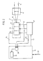
- the matrix detector 4 with charge transfer and frame transfer comprises: a photosensitive zone 12 which receives the pulsed light beam 11 (flashes 8) coming from the beacon 3 and which consists of a plurality of lines of photosensitive elements 5 and over the whole of which said optical system 6 is capable of form an image; this photosensitive area 12 is capable of integrating the electric charges generated by the photons of said image to generate image information in electrical form; - an intermediate memory area 13, which consists of a plurality of rows of memory elements and in which are transferred line to line said electrical image information contained in the lines of said photosensitive area 12; and a read register 14, in which the electrical image information corresponding to each line of the intermediate memory area 13 are transferred in parallel, said read register 14 generating, at its output 15, a video signal representative of the image received from the optical system 6 by the photosensitive zone 12.
- the matrix detector 4 is also associated: a processing unit 16, external to said matrix detector 4 and generating, at its output 17, the parameters defining the acquisition of the images, such as duration of exposure of the images, synchronization of the taking of the images, synchronization of the reading, etc ...; - At least one memory 19 whose access is controlled by a control device 20; the memory 19 and the device 20 are external to the matrix detector 4 and are advantageously incorporated in the processing unit 16; and - A sequencer 21 receiving from the output 17 of the processing unit 16 said image acquisition parameters and responsible for controlling the taking of the image by the photosensitive zone 12 and for regulating the transfer of information.
- the sequencer 21 comprises in particular: - An output 22 on which appears a signal addressed to the photosensitive zone 12 and intended to advance line by line the electrical image information inside said photosensitive zone 12 in the direction of the intermediate memory zone 13; an output 23 on which there appears a signal addressed to the intermediate memory area 13 and intended for advancing the electrical image information line by line within said intermediate memory area 13 toward said read register 14; an output 24 on which there appears a signal addressed to the reading register 14 and intended to control the latter so that it addresses to memory 19, via its output 15 and the control device 20, a video signal serial from the parallel information it receives from the intermediate memory area 13. Furthermore, the output 24 is also connected to said control device 20 of said memory 19; and an output 25 on which appears a validation signal addressed to said control device 20.
- Each of the signals appearing at outputs 22, 23 and 24 of sequencer 21 consists of a series of pulses of constant frequency, each pulse corresponding to a passage from one line to the next (for zones 12 and 13) or to the transformation of a parallel line into a serial line (for the read register 14).
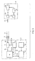
- FIG. 3 schematically shows an embodiment of the system according to the invention, taking account of the diagram of FIG. 2. It can be seen there that the optical transmitter 3 comprises a time base 26 supplying a sequencer 27, controlling an electronic triggering device 28, which itself controls the light source 29 emitting the flashes 8.
- the electronic circuits for controlling the optical detector 2 include a time base 30 connected to a processor 31, activating the processing unit 16 for image acquisition by the control 32.
- the sequencer 27 is connected to the matrix detector 4 by the connections 22, 23 and 24 and to the processing unit 16 by the links 17, 24 and 25.
- the punctual image 10 of the light burst 8 representative of the position of the missile 1 relative to the axis OX, is formed on a particular photosensitive element 5 of this photosensitive zone 12.
- the position of the point image 10 in the photosensitive zone 12 only depends on the position of the missile 1 relative to the axis OX; it is in particular independent of the time relationship between the light flash 8 and the integration time 9.
- the position of the light flash 8 within the integration time 9 has no influence on the position of the image 10 on the photosensitive zone 12.
- the sequencer 21 transmits a signal on its outputs 22 and 23, without transmitting on its output 24.
- the image 10 of the flash 8 is advanced line by line in the direction of the intermediate memory area 13.
- the transfer of the lines from the photosensitive area 12 to the intermediate memory area 13 takes place during the time pulse 33 and is terminated at the instant t4, after t3 .
- the sequencer 21 transmits a signal on its outputs 23 and 24, without transmitting on its output 22, so that the content of the intermediate memory 13 is read by the reading register 14.
- Such a reading extends until time t5, after t4 (see time pulse 34 in Figure 4 d ).
- the content of the intermediate memory 13 is advanced, line by line, to the register 14, then transferred into the latter, which addresses it, by its output 15, in the memory 19. Thanks to the link between the output 24 of the sequencer 21 and the control device 20, the video signal at said output 15 of the playback register 14 is staggered and synchronized by the playback signal appearing at the output 24.
- the image 10.1 of the following brightness 8.1 then appears (see FIG. 5 b ). It will be noted that, given the high frequency of the pulses 9 and of the flashes 8, the position of the image 10.1 is hardly different from that of the image 10.
- the duration tot3 of an integration time 9 is reduced to one value (for example equal to 1 ⁇ s) at most equal to the duration t1t2 of the splinters 8.
- an integration time 9.n has been shown, corresponding to such a reduced integration time. In the two examples shown, it has been assumed that the duration of each time of reduced integration 9.n was less than that of flakes 8.
- the corresponding light brightness 8 partially extends, ie over the duration of the transfer pulses 33 and 34 immediately following the integration time 9.n (case of FIG. 6), either on the elongated transfer pulses 33.n and / or 34.n preceding said integration time. 9.n (case of Figure 7).
- said luminous flash hits in part the photosensitive zone 12, during the transfer of the content thereof, in the intermediate memory zone 13 and / or in the register 14.
- a light trace 35 which extends over several image lines from the image 10 formed by the portion of the chip 8 in temporal correspondence with the reduced integration time 9.n (see FIG. 8) and, in the second case , a light trace 36 which extends over several image lines up to said image 10 (see FIG. 9).
- m F x ⁇ t, expression in which F (for example equal to 2 MHz) is the transfer frequency of the image lines and ⁇ t the offset between the reduced integration time 9.n and the corresponding brightness 8.
- the processor 31 knows the frequency F; moreover, it knows the number of lines m by the control unit 16. It can therefore easily calculate ⁇ t.
- the processor 31 therefore easily calculates the offset T ⁇ ⁇ t (the sign + corresponding to the case of FIG. 6, and the sign - to that of FIG. 7), which the relative drift of the time bases 26 and 30 introduced between integration times 9 and light flashes 8.
- the prior synchronization of the 3-detector beacon 2 is ensured at the start of the missile 1 with sufficient precision (for example 0.5 ⁇ s) to maintain for a few successive images (taken for example at the rate of approximately 50 Hz), the light emission of the flakes 8 (for example 5 to 10 ⁇ s) in short integration times 9 (for example 20 ⁇ s), synchronized in phase and in frequency with the emission of said flakes.
Landscapes
- Engineering & Computer Science (AREA)
- Physics & Mathematics (AREA)
- General Physics & Mathematics (AREA)
- General Engineering & Computer Science (AREA)
- Combustion & Propulsion (AREA)
- Electromagnetism (AREA)
- Chemical & Material Sciences (AREA)
- Radar, Positioning & Navigation (AREA)
- Remote Sensing (AREA)
- Aiming, Guidance, Guns With A Light Source, Armor, Camouflage, And Targets (AREA)
- Length Measuring Devices By Optical Means (AREA)
- Photometry And Measurement Of Optical Pulse Characteristics (AREA)
- Optical Radar Systems And Details Thereof (AREA)
Applications Claiming Priority (2)
| Application Number | Priority Date | Filing Date | Title |
|---|---|---|---|
| FR8913841 | 1989-10-23 | ||
| FR8913841A FR2653562B1 (fr) | 1989-10-23 | 1989-10-23 | Systeme pour la localisation d'un mobile. |
Publications (2)
| Publication Number | Publication Date |
|---|---|
| EP0425355A1 true EP0425355A1 (de) | 1991-05-02 |
| EP0425355B1 EP0425355B1 (de) | 1994-04-20 |
Family
ID=9386661
Family Applications (1)
| Application Number | Title | Priority Date | Filing Date |
|---|---|---|---|
| EP90402962A Expired - Lifetime EP0425355B1 (de) | 1989-10-23 | 1990-10-22 | Ortungssystem für einen beweglichen Körper |
Country Status (7)
| Country | Link |
|---|---|
| US (1) | US5081345A (de) |
| EP (1) | EP0425355B1 (de) |
| JP (1) | JPH03165282A (de) |
| DE (1) | DE69008304T2 (de) |
| DK (1) | DK0425355T3 (de) |
| ES (1) | ES2053146T3 (de) |
| FR (1) | FR2653562B1 (de) |
Cited By (5)
| Publication number | Priority date | Publication date | Assignee | Title |
|---|---|---|---|---|
| FR2676823A1 (fr) * | 1991-04-03 | 1992-11-27 | Saint Louis Inst | Dispositif de mesure de l'ecart d'un projectile. |
| EP0649032A1 (de) * | 1993-10-19 | 1995-04-19 | SAT (Société Anonyme de Télécommunications),Société Anonyme | System zur Lokalisierung von mobilen Objekten |
| EP0668482A1 (de) * | 1994-02-16 | 1995-08-23 | Daimler-Benz Aerospace Aktiengesellschaft | Vorrichtung zur Fernsteuerung eines Flugkörpers |
| EP0751367A1 (de) * | 1995-06-28 | 1997-01-02 | Aerospatiale Societe Nationale Industrielle | Vorrichtung zur Lenkung eines Flugkörpers durch Ausrichten auf ein Ziel |
| FR2908874A1 (fr) * | 2006-11-21 | 2008-05-23 | Mbda France Sa | Systeme de visee a ecartometre integre. |
Families Citing this family (7)
| Publication number | Priority date | Publication date | Assignee | Title |
|---|---|---|---|---|
| US5196689A (en) * | 1990-10-16 | 1993-03-23 | Pioneer Electronic Corporation | Device for detecting an object including a light-sensitive detecting array |
| FR2672989A1 (fr) * | 1991-02-15 | 1992-08-21 | Sodern | Dispositif de determination de la direction d'une source emissive de faible luminosite et son application a la visee stellaire. |
| US5302835A (en) * | 1993-03-22 | 1994-04-12 | Imra America, Inc. | Light detection system having a polarization plane rotating means and a polarizing beamsplitter |
| US5548392A (en) * | 1995-01-31 | 1996-08-20 | Kabushikikaisha Wacom | Optical position detector having scale pattern spot-illuminated to increase resolution |
| US6469783B1 (en) * | 2001-04-19 | 2002-10-22 | Raytheon Company | Solid state modulated beacon tracking system |
| FR2857088B1 (fr) * | 2003-07-04 | 2005-09-16 | Mbda France | Missile tournant emettant des impulsions lumineuses. |
| FR2874434B1 (fr) * | 2004-08-20 | 2006-11-17 | Mbda France Sa | Procede et dispositif pour la realisation d'une liaison optique par eclats lumineux |
Citations (5)
| Publication number | Priority date | Publication date | Assignee | Title |
|---|---|---|---|---|
| US3761180A (en) * | 1972-09-22 | 1973-09-25 | R Maxwell | Synchronously gated active night sight |
| US4027837A (en) * | 1969-10-23 | 1977-06-07 | The United States Of America As Represented By The Secretary Of The Army | Optical tracking link utilizing pulse burst modulation for solid state missile beacons |
| US4197424A (en) * | 1977-01-31 | 1980-04-08 | Echo Keisokuki Kabushiki Kaisha | Standard time signal generator immune to noise induced false locking |
| EP0206912A1 (de) * | 1985-06-17 | 1986-12-30 | AEROSPATIALE Société Nationale Industrielle | System zur Bestimmung der Position eines bewegten Ziels |
| EP0307381A2 (de) * | 1987-09-11 | 1989-03-15 | NDC NETZLER & DAHLGREN CO. AB | Optisches Navigationssystem und Verfahren für automatisch gelenkte Fahrzeuge |
Family Cites Families (4)
| Publication number | Priority date | Publication date | Assignee | Title |
|---|---|---|---|---|
| US4154530A (en) * | 1977-12-22 | 1979-05-15 | National Semiconductor Corporation | Laser beam error correcting process |
| US4419012A (en) * | 1979-09-11 | 1983-12-06 | Elliott Brothers (London) Limited | Position measuring system |
| JPS62220807A (ja) * | 1986-03-20 | 1987-09-29 | Toshiba Corp | スタ−スキヤナ |
| FR2621398B1 (fr) * | 1987-10-02 | 1989-07-28 | Thomson Csf | Dispositif optoelectrique de detection et de localisation d'une source rayonnante |
-
1989
- 1989-10-23 FR FR8913841A patent/FR2653562B1/fr not_active Expired - Fee Related
-
1990
- 1990-10-22 DE DE69008304T patent/DE69008304T2/de not_active Expired - Fee Related
- 1990-10-22 US US07/602,125 patent/US5081345A/en not_active Expired - Lifetime
- 1990-10-22 DK DK90402962.6T patent/DK0425355T3/da active
- 1990-10-22 ES ES90402962T patent/ES2053146T3/es not_active Expired - Lifetime
- 1990-10-22 EP EP90402962A patent/EP0425355B1/de not_active Expired - Lifetime
- 1990-10-23 JP JP2283569A patent/JPH03165282A/ja active Pending
Patent Citations (5)
| Publication number | Priority date | Publication date | Assignee | Title |
|---|---|---|---|---|
| US4027837A (en) * | 1969-10-23 | 1977-06-07 | The United States Of America As Represented By The Secretary Of The Army | Optical tracking link utilizing pulse burst modulation for solid state missile beacons |
| US3761180A (en) * | 1972-09-22 | 1973-09-25 | R Maxwell | Synchronously gated active night sight |
| US4197424A (en) * | 1977-01-31 | 1980-04-08 | Echo Keisokuki Kabushiki Kaisha | Standard time signal generator immune to noise induced false locking |
| EP0206912A1 (de) * | 1985-06-17 | 1986-12-30 | AEROSPATIALE Société Nationale Industrielle | System zur Bestimmung der Position eines bewegten Ziels |
| EP0307381A2 (de) * | 1987-09-11 | 1989-03-15 | NDC NETZLER & DAHLGREN CO. AB | Optisches Navigationssystem und Verfahren für automatisch gelenkte Fahrzeuge |
Cited By (11)
| Publication number | Priority date | Publication date | Assignee | Title |
|---|---|---|---|---|
| FR2676823A1 (fr) * | 1991-04-03 | 1992-11-27 | Saint Louis Inst | Dispositif de mesure de l'ecart d'un projectile. |
| EP0649032A1 (de) * | 1993-10-19 | 1995-04-19 | SAT (Société Anonyme de Télécommunications),Société Anonyme | System zur Lokalisierung von mobilen Objekten |
| FR2711428A1 (fr) * | 1993-10-19 | 1995-04-28 | Sat | Système de localisation de mobile. |
| EP0668482A1 (de) * | 1994-02-16 | 1995-08-23 | Daimler-Benz Aerospace Aktiengesellschaft | Vorrichtung zur Fernsteuerung eines Flugkörpers |
| EP0751367A1 (de) * | 1995-06-28 | 1997-01-02 | Aerospatiale Societe Nationale Industrielle | Vorrichtung zur Lenkung eines Flugkörpers durch Ausrichten auf ein Ziel |
| FR2736146A1 (fr) * | 1995-06-28 | 1997-01-03 | Aerospatiale | Systeme de guidage en alignement d'un missile sur une cible |
| US5762290A (en) * | 1995-06-28 | 1998-06-09 | Aerospatiale Societe Nationale Industrielle | System for guiding a missile in alignment onto a target |
| FR2908874A1 (fr) * | 2006-11-21 | 2008-05-23 | Mbda France Sa | Systeme de visee a ecartometre integre. |
| EP1925902A1 (de) * | 2006-11-21 | 2008-05-28 | MBDA France | Zielvorrichtung mit integriertem Abstandsanzeiger |
| WO2008062114A1 (fr) * | 2006-11-21 | 2008-05-29 | Mbda France | Systeme de visee a ecartometre integre |
| US8022343B2 (en) | 2006-11-21 | 2011-09-20 | Mbda France | Aiming system with integrated deviation meter |
Also Published As
| Publication number | Publication date |
|---|---|
| US5081345A (en) | 1992-01-14 |
| DK0425355T3 (da) | 1994-08-29 |
| DE69008304D1 (de) | 1994-05-26 |
| EP0425355B1 (de) | 1994-04-20 |
| FR2653562A1 (fr) | 1991-04-26 |
| JPH03165282A (ja) | 1991-07-17 |
| FR2653562B1 (fr) | 1992-02-28 |
| ES2053146T3 (es) | 1994-07-16 |
| DE69008304T2 (de) | 1994-09-08 |
Similar Documents
| Publication | Publication Date | Title |
|---|---|---|
| EP0206912B1 (de) | System zur Bestimmung der Position eines bewegten Ziels | |
| EP0425355B1 (de) | Ortungssystem für einen beweglichen Körper | |
| US11212512B2 (en) | System and method of imaging using multiple illumination pulses | |
| EP1925902B1 (de) | Zielvorrichtung mit integriertem Abweichungsanzeiger | |
| US11614517B2 (en) | Reducing interference in an active illumination environment | |
| CH620764A5 (de) | ||
| EP0504022A1 (de) | Optisches Übertragungssystem zwischen mobilen Stationen und entsprechendes Verfahren | |
| JPH02211782A (ja) | 不可視光を使用する結像ライダー | |
| EP2804011B1 (de) | Laserbeleuchtungsvorrichtung mit integrierter Verschlussblende | |
| EP0254634B1 (de) | Verfahren und Vorrichtung zum optischen Abstandsmessen | |
| FR2623353A1 (fr) | Systeme de camera de television | |
| EP0633457B1 (de) | Fotoelement und Vorrichtung zur Detektion von Lichtpulsen | |
| CN105391948A (zh) | 一种具有夜视透雾功能的前端设备及其控制方法 | |
| FR2683635A1 (fr) | Systemes de poursuite de missile. | |
| FR2547059A1 (fr) | Dispositif pour detecter une camera infrarouge adverse | |
| CA2028157C (fr) | Systeme pour la localisation d'un mobile | |
| CA1266523A (fr) | Senseur opto-electronique multichamp a transfert de charges | |
| EP0100387B1 (de) | Optische Anlagen für Annäherungsdetektoren | |
| WO2019193269A1 (fr) | Procede et systeme d'emission et de reception d'impulsions laser | |
| EP0235002B1 (de) | Optoelektronischer Ladungübertragungssensor | |
| FR3058263B1 (fr) | Dispositif de detection multispectrale ameliore. | |
| EP1202021B1 (de) | Vorrichtung zur Justierung eines Lasersendungskanals mit einem passiven Beobachtungskanal | |
| EP0649032B1 (de) | System zur Lokalisierung von mobilen Objekten | |
| FR2700209A1 (fr) | Systèmes de désignation de cible. | |
| Briscoe | 200,000-frame-per-second drum camera with nanosecond synchronized laser illumination |
Legal Events
| Date | Code | Title | Description |
|---|---|---|---|
| PUAI | Public reference made under article 153(3) epc to a published international application that has entered the european phase |
Free format text: ORIGINAL CODE: 0009012 |
|
| AK | Designated contracting states |
Kind code of ref document: A1 Designated state(s): BE DE DK ES GB IT NL SE |
|
| 17P | Request for examination filed |
Effective date: 19910603 |
|
| 17Q | First examination report despatched |
Effective date: 19930709 |
|
| GRAA | (expected) grant |
Free format text: ORIGINAL CODE: 0009210 |
|
| AK | Designated contracting states |
Kind code of ref document: B1 Designated state(s): BE DE DK ES GB IT NL SE |
|
| GBT | Gb: translation of ep patent filed (gb section 77(6)(a)/1977) |
Effective date: 19940420 |
|
| REF | Corresponds to: |
Ref document number: 69008304 Country of ref document: DE Date of ref document: 19940526 |
|
| ITF | It: translation for a ep patent filed | ||
| REG | Reference to a national code |
Ref country code: ES Ref legal event code: FG2A Ref document number: 2053146 Country of ref document: ES Kind code of ref document: T3 |
|
| REG | Reference to a national code |
Ref country code: DK Ref legal event code: T3 |
|
| EAL | Se: european patent in force in sweden |
Ref document number: 90402962.6 |
|
| PLBE | No opposition filed within time limit |
Free format text: ORIGINAL CODE: 0009261 |
|
| STAA | Information on the status of an ep patent application or granted ep patent |
Free format text: STATUS: NO OPPOSITION FILED WITHIN TIME LIMIT |
|
| 26N | No opposition filed | ||
| BERE | Be: lapsed |
Owner name: AEROSPATIALE SOC. NATIONALE INDUSTRIELLE Effective date: 19951031 |
|
| BERR | Be: reestablished | ||
| REG | Reference to a national code |
Ref country code: GB Ref legal event code: IF02 |
|
| PGFP | Annual fee paid to national office [announced via postgrant information from national office to epo] |
Ref country code: BE Payment date: 20020924 Year of fee payment: 13 |
|
| PGFP | Annual fee paid to national office [announced via postgrant information from national office to epo] |
Ref country code: SE Payment date: 20020925 Year of fee payment: 13 |
|
| PGFP | Annual fee paid to national office [announced via postgrant information from national office to epo] |
Ref country code: DE Payment date: 20020930 Year of fee payment: 13 |
|
| PGFP | Annual fee paid to national office [announced via postgrant information from national office to epo] |
Ref country code: GB Payment date: 20021016 Year of fee payment: 13 |
|
| PGFP | Annual fee paid to national office [announced via postgrant information from national office to epo] |
Ref country code: ES Payment date: 20021024 Year of fee payment: 13 |
|
| PGFP | Annual fee paid to national office [announced via postgrant information from national office to epo] |
Ref country code: NL Payment date: 20021031 Year of fee payment: 13 |
|
| PGFP | Annual fee paid to national office [announced via postgrant information from national office to epo] |
Ref country code: DK Payment date: 20030930 Year of fee payment: 14 |
|
| PG25 | Lapsed in a contracting state [announced via postgrant information from national office to epo] |
Ref country code: GB Free format text: LAPSE BECAUSE OF NON-PAYMENT OF DUE FEES Effective date: 20031022 |
|
| PG25 | Lapsed in a contracting state [announced via postgrant information from national office to epo] |
Ref country code: SE Free format text: LAPSE BECAUSE OF NON-PAYMENT OF DUE FEES Effective date: 20031023 Ref country code: ES Free format text: LAPSE BECAUSE OF NON-PAYMENT OF DUE FEES Effective date: 20031023 |
|
| PG25 | Lapsed in a contracting state [announced via postgrant information from national office to epo] |
Ref country code: BE Free format text: LAPSE BECAUSE OF NON-PAYMENT OF DUE FEES Effective date: 20031031 |
|
| BERE | Be: lapsed |
Owner name: *AEROSPATIALE SOC. NATIONALE INDUSTRIELLE Effective date: 20031031 |
|
| PG25 | Lapsed in a contracting state [announced via postgrant information from national office to epo] |
Ref country code: NL Free format text: LAPSE BECAUSE OF NON-PAYMENT OF DUE FEES Effective date: 20040501 Ref country code: DE Free format text: LAPSE BECAUSE OF NON-PAYMENT OF DUE FEES Effective date: 20040501 |
|
| EUG | Se: european patent has lapsed | ||
| GBPC | Gb: european patent ceased through non-payment of renewal fee |
Effective date: 20031022 |
|
| NLV4 | Nl: lapsed or anulled due to non-payment of the annual fee |
Effective date: 20040501 |
|
| PG25 | Lapsed in a contracting state [announced via postgrant information from national office to epo] |
Ref country code: DK Free format text: LAPSE BECAUSE OF NON-PAYMENT OF DUE FEES Effective date: 20041101 |
|
| REG | Reference to a national code |
Ref country code: ES Ref legal event code: FD2A Effective date: 20031023 |
|
| REG | Reference to a national code |
Ref country code: DK Ref legal event code: EBP |
|
| PG25 | Lapsed in a contracting state [announced via postgrant information from national office to epo] |
Ref country code: IT Free format text: LAPSE BECAUSE OF NON-PAYMENT OF DUE FEES;WARNING: LAPSES OF ITALIAN PATENTS WITH EFFECTIVE DATE BEFORE 2007 MAY HAVE OCCURRED AT ANY TIME BEFORE 2007. THE CORRECT EFFECTIVE DATE MAY BE DIFFERENT FROM THE ONE RECORDED. Effective date: 20051022 |