EP0425363A1 - Dampfpumpe mit Gegenstromaustauscher für Luft und Verbrennungsprodukte ohne Zwischenfluid - Google Patents
Dampfpumpe mit Gegenstromaustauscher für Luft und Verbrennungsprodukte ohne Zwischenfluid Download PDFInfo
- Publication number
- EP0425363A1 EP0425363A1 EP90402973A EP90402973A EP0425363A1 EP 0425363 A1 EP0425363 A1 EP 0425363A1 EP 90402973 A EP90402973 A EP 90402973A EP 90402973 A EP90402973 A EP 90402973A EP 0425363 A1 EP0425363 A1 EP 0425363A1
- Authority
- EP
- European Patent Office
- Prior art keywords
- enclosure
- air
- tubes
- steam pump
- combustion
- Prior art date
- Legal status (The legal status is an assumption and is not a legal conclusion. Google has not performed a legal analysis and makes no representation as to the accuracy of the status listed.)
- Granted
Links
- 238000002485 combustion reaction Methods 0.000 title claims abstract description 103
- 239000012530 fluid Substances 0.000 title claims abstract description 40
- XLYOFNOQVPJJNP-UHFFFAOYSA-N water Substances O XLYOFNOQVPJJNP-UHFFFAOYSA-N 0.000 claims abstract description 76
- 239000007921 spray Substances 0.000 claims abstract description 20
- 239000003595 mist Substances 0.000 claims abstract description 16
- 238000000034 method Methods 0.000 claims abstract description 12
- 230000008569 process Effects 0.000 claims abstract description 12
- 239000000779 smoke Substances 0.000 claims description 20
- 238000005507 spraying Methods 0.000 claims description 19
- 238000004891 communication Methods 0.000 claims description 6
- 229920006395 saturated elastomer Polymers 0.000 claims description 5
- 239000002033 PVDF binder Substances 0.000 claims description 4
- 229920002981 polyvinylidene fluoride Polymers 0.000 claims description 4
- 239000004800 polyvinyl chloride Substances 0.000 claims description 3
- 229920002994 synthetic fiber Polymers 0.000 claims description 3
- 238000011144 upstream manufacturing Methods 0.000 claims description 3
- 244000046052 Phaseolus vulgaris Species 0.000 claims description 2
- 235000010627 Phaseolus vulgaris Nutrition 0.000 claims description 2
- 229920000915 polyvinyl chloride Polymers 0.000 claims description 2
- 241001080526 Vertica Species 0.000 claims 1
- 238000000926 separation method Methods 0.000 claims 1
- 230000001590 oxidative effect Effects 0.000 abstract description 3
- 239000007800 oxidant agent Substances 0.000 abstract 1
- 239000003517 fume Substances 0.000 description 24
- 238000005192 partition Methods 0.000 description 18
- 239000007789 gas Substances 0.000 description 7
- 239000007788 liquid Substances 0.000 description 6
- 238000009434 installation Methods 0.000 description 5
- 238000011084 recovery Methods 0.000 description 5
- MWUXSHHQAYIFBG-UHFFFAOYSA-N Nitric oxide Chemical compound O=[N] MWUXSHHQAYIFBG-UHFFFAOYSA-N 0.000 description 3
- 230000015572 biosynthetic process Effects 0.000 description 3
- 238000009833 condensation Methods 0.000 description 3
- 230000005494 condensation Effects 0.000 description 3
- 239000003546 flue gas Substances 0.000 description 3
- 238000010438 heat treatment Methods 0.000 description 3
- 238000002347 injection Methods 0.000 description 3
- 239000007924 injection Substances 0.000 description 3
- 238000004519 manufacturing process Methods 0.000 description 3
- 238000005265 energy consumption Methods 0.000 description 2
- VNWKTOKETHGBQD-UHFFFAOYSA-N methane Chemical compound C VNWKTOKETHGBQD-UHFFFAOYSA-N 0.000 description 2
- 239000007787 solid Substances 0.000 description 2
- 229910001220 stainless steel Inorganic materials 0.000 description 2
- 239000010935 stainless steel Substances 0.000 description 2
- 238000009423 ventilation Methods 0.000 description 2
- UGFAIRIUMAVXCW-UHFFFAOYSA-N Carbon monoxide Chemical compound [O+]#[C-] UGFAIRIUMAVXCW-UHFFFAOYSA-N 0.000 description 1
- 240000008042 Zea mays Species 0.000 description 1
- 230000006978 adaptation Effects 0.000 description 1
- 230000000712 assembly Effects 0.000 description 1
- 238000000429 assembly Methods 0.000 description 1
- QVGXLLKOCUKJST-UHFFFAOYSA-N atomic oxygen Chemical compound [O] QVGXLLKOCUKJST-UHFFFAOYSA-N 0.000 description 1
- 230000008859 change Effects 0.000 description 1
- 230000006835 compression Effects 0.000 description 1
- 238000007906 compression Methods 0.000 description 1
- 238000001816 cooling Methods 0.000 description 1
- 230000008878 coupling Effects 0.000 description 1
- 238000010168 coupling process Methods 0.000 description 1
- 238000005859 coupling reaction Methods 0.000 description 1
- 230000000694 effects Effects 0.000 description 1
- 239000013505 freshwater Substances 0.000 description 1
- 239000012212 insulator Substances 0.000 description 1
- 239000002184 metal Substances 0.000 description 1
- 239000003345 natural gas Substances 0.000 description 1
- 210000000056 organ Anatomy 0.000 description 1
- 238000013021 overheating Methods 0.000 description 1
- 239000001301 oxygen Substances 0.000 description 1
- 229910052760 oxygen Inorganic materials 0.000 description 1
- 230000037452 priming Effects 0.000 description 1
- 230000000750 progressive effect Effects 0.000 description 1
- 238000005086 pumping Methods 0.000 description 1
- 238000004064 recycling Methods 0.000 description 1
- 230000009467 reduction Effects 0.000 description 1
- 239000008400 supply water Substances 0.000 description 1
- 238000009834 vaporization Methods 0.000 description 1
- 230000008016 vaporization Effects 0.000 description 1
Images


Classifications
-
- F—MECHANICAL ENGINEERING; LIGHTING; HEATING; WEAPONS; BLASTING
- F23—COMBUSTION APPARATUS; COMBUSTION PROCESSES
- F23L—SUPPLYING AIR OR NON-COMBUSTIBLE LIQUIDS OR GASES TO COMBUSTION APPARATUS IN GENERAL ; VALVES OR DAMPERS SPECIALLY ADAPTED FOR CONTROLLING AIR SUPPLY OR DRAUGHT IN COMBUSTION APPARATUS; INDUCING DRAUGHT IN COMBUSTION APPARATUS; TOPS FOR CHIMNEYS OR VENTILATING SHAFTS; TERMINALS FOR FLUES
- F23L15/00—Heating of air supplied for combustion
- F23L15/04—Arrangements of recuperators
-
- F—MECHANICAL ENGINEERING; LIGHTING; HEATING; WEAPONS; BLASTING
- F24—HEATING; RANGES; VENTILATING
- F24H—FLUID HEATERS, e.g. WATER OR AIR HEATERS, HAVING HEAT-GENERATING MEANS, e.g. HEAT PUMPS, IN GENERAL
- F24H1/00—Water heaters, e.g. boilers, continuous-flow heaters or water-storage heaters
- F24H1/10—Continuous-flow heaters, i.e. heaters in which heat is generated only while the water is flowing, e.g. with direct contact of the water with the heating medium
- F24H1/107—Continuous-flow heaters, i.e. heaters in which heat is generated only while the water is flowing, e.g. with direct contact of the water with the heating medium using fluid fuel
-
- F—MECHANICAL ENGINEERING; LIGHTING; HEATING; WEAPONS; BLASTING
- F24—HEATING; RANGES; VENTILATING
- F24H—FLUID HEATERS, e.g. WATER OR AIR HEATERS, HAVING HEAT-GENERATING MEANS, e.g. HEAT PUMPS, IN GENERAL
- F24H8/00—Fluid heaters characterised by means for extracting latent heat from flue gases by means of condensation
- F24H8/003—Fluid heaters characterised by means for extracting latent heat from flue gases by means of condensation having means for moistening the combustion air with condensate from the combustion gases
-
- F—MECHANICAL ENGINEERING; LIGHTING; HEATING; WEAPONS; BLASTING
- F28—HEAT EXCHANGE IN GENERAL
- F28D—HEAT-EXCHANGE APPARATUS, NOT PROVIDED FOR IN ANOTHER SUBCLASS, IN WHICH THE HEAT-EXCHANGE MEDIA DO NOT COME INTO DIRECT CONTACT
- F28D5/00—Heat-exchange apparatus having stationary conduit assemblies for one heat-exchange medium only, the media being in contact with different sides of the conduit wall, using the cooling effect of natural or forced evaporation
- F28D5/02—Heat-exchange apparatus having stationary conduit assemblies for one heat-exchange medium only, the media being in contact with different sides of the conduit wall, using the cooling effect of natural or forced evaporation in which the evaporating medium flows in a continuous film or trickles freely over the conduits
-
- F—MECHANICAL ENGINEERING; LIGHTING; HEATING; WEAPONS; BLASTING
- F28—HEAT EXCHANGE IN GENERAL
- F28D—HEAT-EXCHANGE APPARATUS, NOT PROVIDED FOR IN ANOTHER SUBCLASS, IN WHICH THE HEAT-EXCHANGE MEDIA DO NOT COME INTO DIRECT CONTACT
- F28D7/00—Heat-exchange apparatus having stationary tubular conduit assemblies for both heat-exchange media, the media being in contact with different sides of a conduit wall
- F28D7/16—Heat-exchange apparatus having stationary tubular conduit assemblies for both heat-exchange media, the media being in contact with different sides of a conduit wall the conduits being arranged in parallel spaced relation
-
- F—MECHANICAL ENGINEERING; LIGHTING; HEATING; WEAPONS; BLASTING
- F28—HEAT EXCHANGE IN GENERAL
- F28F—DETAILS OF HEAT-EXCHANGE AND HEAT-TRANSFER APPARATUS, OF GENERAL APPLICATION
- F28F13/00—Arrangements for modifying heat-transfer, e.g. increasing, decreasing
- F28F13/04—Arrangements for modifying heat-transfer, e.g. increasing, decreasing by preventing the formation of continuous films of condensate on heat-exchange surfaces, e.g. by promoting droplet formation
-
- Y—GENERAL TAGGING OF NEW TECHNOLOGICAL DEVELOPMENTS; GENERAL TAGGING OF CROSS-SECTIONAL TECHNOLOGIES SPANNING OVER SEVERAL SECTIONS OF THE IPC; TECHNICAL SUBJECTS COVERED BY FORMER USPC CROSS-REFERENCE ART COLLECTIONS [XRACs] AND DIGESTS
- Y02—TECHNOLOGIES OR APPLICATIONS FOR MITIGATION OR ADAPTATION AGAINST CLIMATE CHANGE
- Y02B—CLIMATE CHANGE MITIGATION TECHNOLOGIES RELATED TO BUILDINGS, e.g. HOUSING, HOUSE APPLIANCES OR RELATED END-USER APPLICATIONS
- Y02B30/00—Energy efficient heating, ventilation or air conditioning [HVAC]
-
- Y—GENERAL TAGGING OF NEW TECHNOLOGICAL DEVELOPMENTS; GENERAL TAGGING OF CROSS-SECTIONAL TECHNOLOGIES SPANNING OVER SEVERAL SECTIONS OF THE IPC; TECHNICAL SUBJECTS COVERED BY FORMER USPC CROSS-REFERENCE ART COLLECTIONS [XRACs] AND DIGESTS
- Y02—TECHNOLOGIES OR APPLICATIONS FOR MITIGATION OR ADAPTATION AGAINST CLIMATE CHANGE
- Y02E—REDUCTION OF GREENHOUSE GAS [GHG] EMISSIONS, RELATED TO ENERGY GENERATION, TRANSMISSION OR DISTRIBUTION
- Y02E20/00—Combustion technologies with mitigation potential
- Y02E20/34—Indirect CO2mitigation, i.e. by acting on non CO2directly related matters of the process, e.g. pre-heating or heat recovery
-
- Y—GENERAL TAGGING OF NEW TECHNOLOGICAL DEVELOPMENTS; GENERAL TAGGING OF CROSS-SECTIONAL TECHNOLOGIES SPANNING OVER SEVERAL SECTIONS OF THE IPC; TECHNICAL SUBJECTS COVERED BY FORMER USPC CROSS-REFERENCE ART COLLECTIONS [XRACs] AND DIGESTS
- Y10—TECHNICAL SUBJECTS COVERED BY FORMER USPC
- Y10S—TECHNICAL SUBJECTS COVERED BY FORMER USPC CROSS-REFERENCE ART COLLECTIONS [XRACs] AND DIGESTS
- Y10S122/00—Liquid heaters and vaporizers
- Y10S122/01—Air heater
-
- Y—GENERAL TAGGING OF NEW TECHNOLOGICAL DEVELOPMENTS; GENERAL TAGGING OF CROSS-SECTIONAL TECHNOLOGIES SPANNING OVER SEVERAL SECTIONS OF THE IPC; TECHNICAL SUBJECTS COVERED BY FORMER USPC CROSS-REFERENCE ART COLLECTIONS [XRACs] AND DIGESTS
- Y10—TECHNICAL SUBJECTS COVERED BY FORMER USPC
- Y10S—TECHNICAL SUBJECTS COVERED BY FORMER USPC CROSS-REFERENCE ART COLLECTIONS [XRACs] AND DIGESTS
- Y10S165/00—Heat exchange
- Y10S165/909—Regeneration
Definitions
- the present invention relates to a steam pump constituted by a mass and heat exchanger ensuring energy transfers between the combustion products from a thermal process and the incoming combustion air.
- Document FR-B-2 446 460 has thus proposed a condensation heating installation comprising a heat exchanger-recuperator for thermally coupling the combustion air necessary for the heat generator with combustion products originating from the heat generator, humidification means being provided for removing at least a portion of the condensates from the combustion products and for bringing these condensates into contact with the combustion air.
- This known exchanger comprises a plurality of juxtaposed compartments separated by vertical partitions and communicating at their ends with lower and upper chambers, a first series of alternating compartments being in communication at a first end with a first lower chamber and at a second end with a first upper chamber while the compartments immediately adjacent to the alternating compartments of the first series communicate with a second upper chamber at their end close to said first end and with a second lower chamber at their end close to said second end.
- the alternating compartments communicating with the first upper and lower chambers are traversed by air to be heated while the alternating compartments communicating with the second upper and lower chambers are traversed by combustion products.
- a first series of supply ramps condensate is installed at the upper end of the compartments of the first series while a second series of condensate supply ramps is installed at the upper end of the compartments of the second series.
- Such a type of mass and heat exchanger proves to be very bulky, difficult to produce and expensive if it is desired to obtain high efficiency.
- it ensures cross-flow exchanges and most of the time leads to excessive humidification of the fumes or to a phenomenon of condensate runoff on either side of the walls of the exchanger which often causes a decrease in the efficiency of the heat exchange.
- condensate control is difficult to carry out and, moreover, auxiliary pumping or ventilation installations involve energy consumption which is often not negligible.
- document FR-A-2 508 616 has proposed a device for treating relatively hot and humid gases, such as smoke, and relatively dry and fresh gases, such as oxidizing gases from a fireplace, for recover the heat and possibly the condensates from the fumes and heat and humidify the combustion air.
- This known treatment device however uses two separate enclosures traversed one by hot and humid gases and the other by relatively dry and fresh gases, each of the enclosures comprising at its upper part means for spraying liquids constituted by condensates recovered during treatment. Again, such a treatment device is bulky due to the presence of two enclosures and is of an efficiency which, although acceptable, remains limited.
- the present invention aims to remedy the drawbacks mentioned above and to make it possible to obtain increased efficiency in recycling the enthalpy of the products of combustion with a heat and mass exchanger, the size of which as well as the manufacturing and operating costs are reduced.
- Another object of the invention is to produce a heat and mass exchanger, also known as a steam pump, which can be used in combination with various thermal processes, whether or not associated with condensers, without the need for delicate adaptations. , especially in the case of large installations, such as boiler rooms using condensing boilers.
- a steam pump consisting of a mass and heat exchanger ensuring energy transfers between combustion air and combustion products from a thermal process and the incoming combustion air, characterized in that it comprises an external enclosure, a set of tubes forming a heat exchanger arranged inside the enclosure in the longitudinal direction of the latter and opening at their ends at a first radial plane and a second plane radial in which are arranged means ensuring the positioning and the support of the tubes with respect to the enclosure as well as the obturation of the free spaces of the section of the enclosure situated outside the tubes, so as to define between said radial planes a first gaseous fluid circulation circuit inside the tubes and a second separate gaseous fluid circulation circuit inside the enclosure but outside the tubes, an orifice for introducing a first gaseous fluid inside the enclosure in said second circuit, an orifice for evacuating outside the enclosure of said first gaseous fluid circulating in said second circuit, an orifice introduction of a second gaseous fluid inside the enclosure into said first circuit and a discharge
- the tubes have smooth walls and are advantageously constituted by tubes with a large exchange surface, such as tubes with a "bean” shaped section having two portions of larger diameter placed in communication using a portion close bond.
- the tubes of the air-combustion products exchanger can be made of a synthetic material, such as polyvinylidene fluoride (PVDF) or polyvinyl chloride (PVC), but can also be metallic. , in stainless steel for example.
- PVDF polyvinylidene fluoride
- PVC polyvinyl chloride
- each nozzle forming an element of the humidification means produces a jet in the form of a solid cone, and comprises a multiplicity of outlet orifices ensuring the spraying of water according to a fine mist. throughout the volume of a cone, the top of which is substantially formed by the top of the nozzle.
- the different nozzles are arranged so that the Water spray cones overlap.
- the enclosure is arranged vertically and the humidification means comprise a first set of nozzles directed downwards and arranged at the upper part of the enclosure so as to spray water over all the section of the enclosure located above the end of the tubes constituting the air-smoke exchanger and a second set of nozzles oriented upwards and arranged at the bottom of the enclosure so as to spray water over the entire section of the enclosure located below the tubes.
- air is introduced into the first gaseous fluid circulation circuit inside the tubes and the combustion products are introduced into the second gaseous fluid circulation circuit inside the enclosure, but outside the tubes.
- the enclosure is arranged horizontally and the humidification means comprise a set of nozzles oriented downwards and arranged at the upper part of the horizontal enclosure while being distributed over the entire length of the enclosure between the air inlet and outlet ports.
- the combustion products are introduced into the first gaseous fluid circulation circuit inside the tubes and air is introduced into the second gaseous fluid circulation circuit inside of the enclosure, but outside the tubes.
- the steam pump according to the invention is advantageously used in combination with a thermal process already associated with a traditional condenser and can thus constitute a an over-condenser in which the air humidification means are supplied with water from a tank containing the condensates from a first condenser.
- the steam pump according to the invention can also be advantageously used in combination with a process or thermal generator with direct contact of the scrubber or submerged combustion type, the air humidification means being able to be supplied with water from the recovery block. generator condensate.
- the steam pump further comprises an air valve disposed in an outlet duct connected to the outlet port of humid combustion air to prevent entrainment of water by capillarity towards the combustion member. associated with this thermal process.
- the steam pump according to the invention can comprise several stages connected in cascade and each comprising a common enclosure with a tubular air-combustion products of combustion against the current without intermediate fluid.
- the steam pump may comprise several tubular air-combustion products of countercurrent combustion product without intermediate fluid disposed inside said common enclosure in compartments separated by vertical walls provided with a first opening at one of their ends for the passage of air between two adjacent compartments, and a second opening made in the vicinity of the other end del enclosure for the passage of the flow of combustion products in a vertical partition wall between compartments, maintaining separate circulation circuits against the current for air and combustion products.
- the steam pump may further comprise a turbo-compressor comprising a compressor located on a combustion air transport pipe connected to the outlet outlet for saturated and heated air and a turbine located on the combustion products outlet pipe after passing through the steam pump so that the combustion products are kept under pressure in the steam pump while the combustion air is maintained at ambient atmospheric pressure during its passage in the steam pump.
- a turbo-compressor comprising a compressor located on a combustion air transport pipe connected to the outlet outlet for saturated and heated air and a turbine located on the combustion products outlet pipe after passing through the steam pump so that the combustion products are kept under pressure in the steam pump while the combustion air is maintained at ambient atmospheric pressure during its passage in the steam pump.
- the steam pump may also include a superheater arranged upstream of the compressor on said combustion air transport pipe.
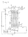
- FIG. 1 a first example of a steam pump, or mass and heat exchanger, according to the invention.
- This steam pump 10 essentially comprises a common vertical enclosure 11 inside which heat exchanges take place between smoke and combustion air.
- a set of vertical tubular walls 12 are arranged inside the enclosure 11 in such a way that, in this example, the external face of the walls of the tubes 12 is in contact with the fumes which are not humidified while the face internal walls of the tubes 12 is in contact with the oxidizing fresh air which circulates in the enclosure 11 inside the tubes 12 and is humidified by means 20, 30 of spraying water or condensates.
- An orifice 15 for introducing fresh air is formed in the enclosure 11 in the vicinity of the bottom 52 thereof and under a lower partition 54 for supporting the tubes 12 and for closing the free spaces between the tubes 12 while an orifice 16 for evacuating heated and humidified air is formed in the enclosure 11 in the vicinity of the upper part 51 thereof and above an upper partition 53 for supporting the tubes 12 and for closing off free spaces between the tubes 12.
- a pipe 13 for supplying hot smoke passes through the enclosure 11 at a level situated just below the orifice 16 for evacuating the heated air, and under the partition upper horizontal 53 while a pipe 14 for evacuating cold smoke crosses the enclosure 14 at a level situated just above the orifice 15 for introducing fresh combustion air and above the lower horizontal partition 54
- the fumes symbolized by the arrows 5 thus circulate in the duct 13 for supplying the fumes which is in communication with the passages included in the enclosure 11 between the horizontal partitions 53 and 54 and situated outside the tubes 12, then after having circulated from top to bottom between the partitions 53 and 54, they exit from the steam pump 10 via the outlet pipe 14.
- the air symbolized by arrows 6 circulates against the current with respect to the fumes 5, that is to say from bottom to top.
- the relatively cold and dry fresh air is humidified by a first humidification device 30 placed at the lower part of the enclosure 11 under the partition 54 and made so as to spray a fine mist into the entire air inlet section inside the tubes 12 at the level of the partition 54, the mist being produced in the same direction as the air flow, this is ie up.
- a second humidification device 20 is disposed at the upper part of the enclosure 11 and is produced so as to spray a fine mist into the entire air outlet section formed by the outlet sections of the tubes 12 passing through the upper partition 53, the fine mist being produced downwards, that is to say against the current with respect to the air flow emerging from the tubes 12.
- the mists produced by the water injection devices 20 and 30 contribute humidify the combustion air and cause water to run off on the internal face of the walls of the tubes 12 which constitute the exchanger proper.
- the air and the water sprayed into the air heat up by contact with the internal faces of the walls of the tubes 12, the external faces of which are in contact with the combustion products. This results in vaporization of the water droplets, the progressive saturation of the air of combustion and condensation in combustion products.
- each tube 12 advantageously have a section of particular shape which improves the efficiency of the exchange. As shown in FIG. 3, each tube 12 can thus have a bean-shaped section with two portions of larger section joined by a narrow connecting portion at the level of which a venturi effect is produced which maintains turbulence at the level of the gas flow circulating inside the tube.
- the presence of a groove on the external face of the bean-shaped tubes, that is to say on the side of the flue gas circulation makes it possible to permanently break the film of water formed by the condensates and this prevents them from behaving like an insulating film.
- the condensate film can break naturally due to the fact that a large body of water collects in the throat and can come off by its own weight.
- the tubes 12 can be metallic, for example stainless steel.
- the exchanger is capable of operating with fumes being at relatively low temperatures, in particular in the case of the association of the steam pump with a direct contact generator, the tubes 12 can be produced in synthetic materials such as PVC or PVDF.
- a boiler producing hot water or steam necessary for heating or a process and equipped with a forced air burner can be associated with a condenser in which the water in return for use or cold make-up water is used in a first exchange phase to cool the combustion products. Cooling causes the condensation of water vapor from combustion when the inlet temperature of the fluid to be heated is below the dew point of the combustion products.
- the condenser used makes it possible to lower the temperature of the combustion products to a temperature which is of the order of 45 ° C.
- the combustion products already partially cooled and relieved of part of their vapor of water introduced into a steam pump according to the invention will yield a greater or lesser part of the energy which they still contain in the form of recycled energy with the combustion air preheated and humidified by its passage through the pump to steam.
- the steam pump according to the invention allows a reduction in the formation of nitrogen oxide which is often very significant (greater than 50%). This phenomenon is due to the production of a cooler flame due to the "doping" in water vapor of the combustion air and to the concomitant depletion of oxygen in the combustion air.
- An important aspect of the present invention is linked to the spraying of water which is carried out only through the air flow and not through the smoke flow.
- a water tank 23 which can be for example a condensate collector from a condensing generator or a condenser on water associated with a conventional boiler, but could also be a tank of water from an outside source.
- the steam pump according to the invention requires only the use of a relatively small amount of water which can be pumped by a pump 22 at low flow rate which can operate with a low electrical power, for example from the order of a few kilowatts.
- the water pumped by the pump 22 into the reservoir 23 is applied by a line 21 to the upper spray head 20 which is only shown schematically in FIG. 1, but is designed to inject the water in the form of mist in the entire section of the enclosure 11 which is located above the exchanger formed from the tubes 12 and constitutes the outlet section of the heated air intended to be discharged through the outlet orifice 16.
- the second head 30 for spraying water can be produced in a similar manner to that of the upper head 20 for injecting the water in the form of a mist over the entire section of the enclosure 11 which is situated below the exchanger formed from tubes 12 and constitutes the inlet section of the fresh air introduced through the inlet orifice 15.
- Water can be applied to the lower spray head 30 by a pipe 31 supplied by a pump 32 from the water contained in a tank 33.
- the tank 33 can receive by a line 34 condensates collected at the bottom of the tubes 12.
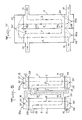
- FIG. 2 shows an alternative embodiment of FIG. 1, in which the upper 20 and lower 30 spray heads, which constitute the means for humidifying the air introduced into the enclosure 11, are supplied using '' a single pump 22 by lines 21 and 26 from the same tank 23 which can be a condensate collector of a condenser as indicated above. Valves 24, 25 are arranged on the pipes 21 and 26 to adjust the water injection rate through the spray heads 20 and 30.
- FIG. 2 which constitutes an embodiment which does not require the using only a single electric pump 22, the condensates formed in the exchanger outside the tubes 12 can be brought back by a pipe 34 to the tank 23.
- FIGs 1 and 2 there is shown an air valve which is disposed in an outlet duct connected to the air outlet orifice 16.
- the valve 40 thus prevents a entrainment of water by capillarity towards the burner and thus prevents the safety members associated with the burner from decommissioning the latter.
- the steam pump according to the invention is particularly suitable for operating in combination with a condensing heat generator, as already indicated above, but can be installed on any thermal equipment by means of a mechanical recovery or ventilation member.
- the steam pump associated with a condensing heat generator can constitute a self-priming device that does not require the addition of fresh water outside at start-up if a condensate recovery and control system is provided.
- a steam pump according to the invention because it leads to the rejection of cold and not very humid fumes, makes it possible to avoid carrying out casing of the chimneys which is always expensive.
- Each water spray head 20, 30 comprises a spray boom 21, 31 provided with a series of nozzles 1 which may have an essentially conical shape and comprise on their large end face 2 a series of small orifices 3 regularly distributed over the whole surface constituting the base of the cone.
- Each nozzle 1 thus ensures the projection, in the form of a fine mist, of fine water droplets 4 throughout the interior volume to a cone whose apex is located at the level of the nozzle 1.
- These nozzles 1 are arranged such so that the conical volumes filled with water droplets 4 overlap.
- Each device 20, 30 thus ensures the projection of a mist into the entire volume delimited by the part of the enclosure 11 in which the inlet orifice 15 resp. Is formed. 16 air outlet and an end plate 53 resp. 54 for supporting the ends of the tubes 12 in which the combustion air circulates.
- the lower water spray head 30, situated at the level of the air inlet orifice 15, is arranged so that the water droplets are projected upwards in the direction of air circulation.
- the spraying of water carried out at the lower part of the exchanger causes an oversaturation of the air at the foot of the exchanger and facilitates priming at low temperature.
- the spraying of water carried out at the top of the exchanger in the vicinity of the air outlet is itself carried out against the current with respect to the flow of air circulation.
- the heads 20, 30 for spraying water form a fine mist only in the flow of combustion air and no water droplet is projected into the smoke circulation circuit, which is isolated by partitions 53, 54 and the walls of the tubes 12.
- a steam pump according to the invention can comprise a single stage, as shown in FIGS. 1, 2 and 4, or several similar stages arranged in cascade, as shown in FIG. 6.
- FIG. 6 shows a steam pump comprising two units 10a, 10b which may each be identical to the steam pump of FIG. 4 for example, each with a common enclosure 11 inside which are arranged sets of exchanger tubes 12 , not shown in Figure 6, and water spraying means 20, 30 arranged at the top and bottom of each enclosure 11.
- the orifice 16 for air outlet of the first unit 10a is connected by a pipe 7 to the air inlet 15 of the second unit 10b.
- the pipe 14 for the smoke outlet from the first unit 10a is connected by a connecting pipe 8 to the pipe 13 for the smoke inlet from the second unit 10b.
- FIG. 6 as in FIGS. 7 and 9, the path of the fumes is symbolized by broken lines 5 while the path of air is symbolized by broken lines 6.
- the operation of the steam pump of FIG. 6 will not be described in more detail since each unit 10a, 10b behaves like the steam pump of FIGS. 1, 2 or 4.
- Figure 7 shows an embodiment quite similar to that of Figure 6, but in which several stages (two stages in the example shown) of exchange are arranged in series in the same enclosure 11.
- these partitions 55, 56 separate two consecutive stages and orifices 14b, 16b are formed in the partitions 55, 56 to constitute zones for the passage of smoke and air between the two successive stages.
- the direction of circulation of the fumes 5 and of the air 6 are reversed in the second stage with respect to the first stage, so that for a two-stage steam pump integrated in the same enclosure 11 as shown in FIG. 7, l orifice 16 for evacuating air is located at the bottom of the enclosure 11 while the smoke outlet pipe 14 is located at the top of the enclosure 11.
- a third stage would make it possible to find outlet openings arranged as according to the embodiment of FIG. 4.
- a single spray boom of water 20 can be used at the upper part of the enclosure 11 while two separate water spraying ramps 30a, 30b are arranged at the bottom of the enclosure 11 in two compartments separated by a partition 56.
- Each ramp spraying 20, 30a, 30b can be carried out as described with reference to FIGS. 4 and 5.
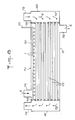
- FIG. 8 represents a second embodiment of a steam pump 110 according to the invention, which differs from the embodiment of FIG. 4 essentially by the horizontal arrangement of the enclosure 111 which has two lateral end faces 151, 152.
- the tubes 112 constituting the actual exchanger between the air and the combustion products can be quite similar to the tubes 12 of FIGS. 1 to 4, but are arranged horizontally between two vertical end plates 153, 154 serving as support for the tubes 112 with respect to the enclosure 111 and for partitions between the air and smoke circuits.
- a fresh air inlet orifice 115 is formed at the upper part of the enclosure 111, in the vicinity of the tube support plate 153 112, and allows the supply of fresh air to the volume comprised between the enclosure 111 and the tubes 153, 154 for supporting the tubes 112, the air 6 flowing, from left to right in FIG. 8, around the tubes 112 in the longitudinal direction of the enclosure 111, towards an air outlet orifice 116 located at the lower part of the enclosure 111 in the vicinity of the tube support plate 154.
- a smoke transport pipe 113 opens into a chamber 157 delimited by the lateral end 152 of the enclosure, the tube support plate 154 and a part of the enclosure 111, to allow the introduction of the fumes to the inside the tubes 112, one end of which opens into the chamber 157.
- Each of the tubes 112 opens at its end located at the level of the plate 153 in a second lateral chamber 158 delimited by the lateral end 151 of the enclosure, the plate 153 for supporting the tubes and part of the enclosure 111.
- a pipe 114 for evacuating the fumes towards the outside is in communication with the chamber 158.
- the fumes 5 circulate inside the tubes 112 (from right to left in Figure 8) while the combustion air circulates outside the tubes 112 essentially against the current (i.e. from left to right in the figure 8).
- a vertical chamber steam pump such as that described with reference to FIGS.
- Humidification means 120 constituted by a water spraying boom 121 provided with a set of nozzles 1, is disposed inside the enclosure 111, at the upper part thereof and extends over the entire length of the exchanger consisting of the tubes 112, that is to say over the entire length between the support plates 153 and 154.
- the spraying boom 120 is thus arranged so as to allow the formation of an end fog not only at the level of the section of the enclosure adjacent to the air inlet orifice 115 and at the level of the section of the enclosure 111 adjacent to the air outlet orifice 116, but also on the entire intermediate zone where the heat exchanges take place through the walls of the tubes 112.
- the spraying of water all along the exchanger contributes to "breaking" the temperature gradients and therefore to maintaining a temperature at little near constant in all the sections of the enclosure from the air inlet 115 to the air outlet 116 while in a steam pump with a vertical enclosure such as that of FIG. 4 the exchanges between the air and the fumes through the walls of the tubes 12 cause a change in temperature depending on the sections of the enclosure.
- the water is sprayed using jets 1 producing a jet in the form of a solid cone, which are similar to the nozzles already described with reference to Figures 4 and 5, and project fine water droplets into conical volumes which overlap so as to create a fine mist throughout space inside the enclosure 111 and external to the tubes 112 in which the combustion air circulates.
- Figure 9 shows the cascade implementation of two units 110a, 110b similar to the unit of Figure 8 to form a two-stage steam pump in series.
- the air outlet port 116a of the first unit 10a is connected by a pipe 107 to the inlet port 115b of air from the second unit 10b and the smoke outlet pipe 114b from the second unit 110b is connected by a connecting pipe 108 to the smoke inlet pipe 113a from the first unit 110a.
- the number of horizontal exchange units 110a, 110b connected in series can naturally be greater than two.
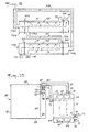
- FIG. 10 shows the application of a steam pump 10 according to the invention not to a condensing boiler or the like, but to a direct contact heat generator.
- FIG. 10 thus shows a heat generator 90 comprising a combustion chamber 94 opening through an opening 95 in an enclosure 91 containing a bath or a zone 93 allowing the heating of a fluid by proceeding by direct contact with the products of combustion 94 through an air inlet orifice 96.
- Combustible fluid such as natural gas
- the enclosure 91 is closed at its upper part by a cover 92 which can be removable.
- the steam products leaving the bath 93 are collected under the cover 92 and evacuated by at least one orifice 97 for evacuating the fumes from the enclosure 91.
- FIG. 10 shows a bath of liquid 93, such as water, which corresponds to the case of submerged combustion, but the invention applies in the same way to the case of a process proceeding by contact.
- a liquid such as a washer-scrubber type device in which a liquid such as water is sprayed into a spray boom arranged in the enclosure at a predetermined level above the bottom of the enclosure 91, the sprayed liquid being brought into direct contact with the combustion products, and the liquid condensates being recovered in the bottom of the enclosure 91.
- FIG 10 there is shown a steam pump 10 according to the invention, which can be in accordance with any of the previously described embodiments and which is connected between the orifice 97 for evacuating the fumes from the enclosure 91 and the orifice 96 for inlet of combustion air into the combustion chamber 94.
- the steam pump 10 is itself provided with at least one fresh air inlet orifice 6, a orifice 14 for the outlet of the fumes, an orifice 16 for the outlet of hot humid air connected by a pipe 81 to the orifice 96 for the entry of air into the combustion chamber 94 and an orifice 13 for the inlet of saturated smoke connected by a pipe 82 to the orifice 97 for evacuating the smoke outside the enclosure 91.
- Figure 10 also shows that it is possible to add to the steam pump 10 pressurizing means located on the side of the combustion products while atmospheric pressure is maintained on the side of the combustion air.
- the pressurizing means may comprise a compressor driven by an electric motor on the air circulating in the pipe 81 connecting the air outlet orifice 16 of the steam pump at the orifice 96 for entry of combustion air into the combustion chamber 94. In this case, however, there is no recovery of expansion energy on the flue gases.
- the pressurizing means comprise a small turbo-compressor 70 which in particular makes it possible to recover the expansion energy at the level of the fumes.
- This turbo-compressor comprises a compressor 71 disposed between the steam pump 10 and the combustion chamber 94 upstream of the orifice 96 for the entry of combustion air into the combustion chamber 94 and a turbine 72 advantageously disposed on the device.
- a motor, or a motor-compressor 73 for starting and making up can also be implemented on the pipe 81 for transferring the combustion air. It will be noted that the expansion compression device 70 can be placed in the vicinity of the combustion chamber 94 and of the enclosure 91 or, on the contrary, placed on the pipes 81, 82 in the vicinity of the steam pump 10.
- a superheater 80 on the duct 81 for transfer of combustion air, which acts on the humid air leaving the steam pump before it enters the compressor 71. If the air is saturated, a minimum overheating of 5 ° C is generally desirable.
- the superheater 80 can be constituted for example by a heat exchanger performing an exchange between the fumes leaving the bath 93 which escape through the orifice 97 of the enclosure 91 and the humid air coming from the steam pump 10 which is transferred via line 81.
Landscapes
- Engineering & Computer Science (AREA)
- Mechanical Engineering (AREA)
- General Engineering & Computer Science (AREA)
- Physics & Mathematics (AREA)
- Thermal Sciences (AREA)
- Chemical & Material Sciences (AREA)
- Combustion & Propulsion (AREA)
- Heat-Exchange Devices With Radiators And Conduit Assemblies (AREA)
- Air Humidification (AREA)
- Eye Examination Apparatus (AREA)
- Fluidized-Bed Combustion And Resonant Combustion (AREA)
- Engine Equipment That Uses Special Cycles (AREA)
- Hydrogen, Water And Hydrids (AREA)
- Air Supply (AREA)
- Container, Conveyance, Adherence, Positioning, Of Wafer (AREA)
- Portable Nailing Machines And Staplers (AREA)
Applications Claiming Priority (2)
| Application Number | Priority Date | Filing Date | Title |
|---|---|---|---|
| FR8913945A FR2653544B1 (fr) | 1989-10-24 | 1989-10-24 | Pompe a vapeur a echangeur air-produits de combustion a contre-courant sans fluide intermediaire. |
| FR8913945 | 1989-10-24 |
Publications (2)
| Publication Number | Publication Date |
|---|---|
| EP0425363A1 true EP0425363A1 (de) | 1991-05-02 |
| EP0425363B1 EP0425363B1 (de) | 1994-07-20 |
Family
ID=9386736
Family Applications (1)
| Application Number | Title | Priority Date | Filing Date |
|---|---|---|---|
| EP90402973A Expired - Lifetime EP0425363B1 (de) | 1989-10-24 | 1990-10-23 | Dampfpumpe mit Gegenstromaustauscher für Luft und Verbrennungsprodukte ohne Zwischenfluid |
Country Status (8)
| Country | Link |
|---|---|
| US (1) | US5178210A (de) |
| EP (1) | EP0425363B1 (de) |
| JP (1) | JP3051440B2 (de) |
| AT (1) | ATE108888T1 (de) |
| CA (1) | CA2028485C (de) |
| DE (1) | DE69010830T2 (de) |
| FR (1) | FR2653544B1 (de) |
| NO (1) | NO175021C (de) |
Cited By (6)
| Publication number | Priority date | Publication date | Assignee | Title |
|---|---|---|---|---|
| AU644344B3 (en) * | 1991-11-04 | 1993-12-02 | Donald John Nairn | A shaker rod for a harvester |
| FR2731506A1 (fr) * | 1995-03-08 | 1996-09-13 | Inst Gas Technology | Appareil et procede de chauffage de liquide par contact direct et indirect |
| WO1997047935A1 (en) * | 1996-06-07 | 1997-12-18 | Valmet Corporation | Heat exchanger |
| DE19518076C2 (de) * | 1995-05-17 | 2000-05-04 | Juergen Kuck | Schornsteinsystem für einen Brennwertkessel |
| CN104964586A (zh) * | 2015-07-03 | 2015-10-07 | 新疆蓝德精细石油化工股份有限公司 | 降低丁二烯自聚物的换热器及其使用方法 |
| WO2025026713A1 (fr) | 2023-07-31 | 2025-02-06 | Fives Stein | Bruleur à impulsion variable |
Families Citing this family (32)
| Publication number | Priority date | Publication date | Assignee | Title |
|---|---|---|---|---|
| US6129973A (en) * | 1994-07-29 | 2000-10-10 | Battelle Memorial Institute | Microchannel laminated mass exchanger and method of making |
| DE19653256A1 (de) * | 1996-12-20 | 1998-06-25 | Asea Brown Boveri | Kondensator für binäre/polynäre Kondensation |
| JP3091860B1 (ja) * | 1999-05-31 | 2000-09-25 | 春男 上原 | 吸収器 |
| JP4130555B2 (ja) * | 2002-07-18 | 2008-08-06 | 住友精密工業株式会社 | ガス加湿装置 |
| IL166089A0 (en) * | 2002-07-20 | 2006-01-15 | Idalex Technologies Inc | Evaporative duplex counterheat exchanger |
| US20050189097A1 (en) * | 2004-03-01 | 2005-09-01 | The Boeing Company | Formed sheet heat exchanger |
| NO20043150D0 (no) * | 2004-07-23 | 2004-07-23 | Ntnu Technology Transfer As | "Fremgangsmate og utstyr for varmegjenvining" |
| US20060196968A1 (en) * | 2005-02-17 | 2006-09-07 | Rabin Barry H | Controlled formation of vapor and liquid droplet jets from liquids |
| US20100142934A1 (en) * | 2005-12-01 | 2010-06-10 | Vapore, Inc. | Advanced Capillary Force Vaporizers |
| FR2900719B1 (fr) * | 2006-05-02 | 2008-07-25 | Claude Somajini | Chauffe-eau plat |
| US8105076B2 (en) * | 2007-08-06 | 2012-01-31 | Thomas & Betts International, Inc. | High efficiency radiant heater |
| DE102007050799B3 (de) * | 2007-10-24 | 2008-10-23 | Cfc Solutions Gmbh | Einrichtung zur Befeuchtung und Erhitzung eines zu reformierenden Brenngases für eine Brennstoffzellenanlage |
| US8201752B2 (en) * | 2008-03-10 | 2012-06-19 | Vapore, Inc. | Low energy vaporization of liquids: apparatus and methods |
| US20100119984A1 (en) * | 2008-11-10 | 2010-05-13 | Fox Allen G | Abatement system |
| US20100143222A1 (en) * | 2008-11-10 | 2010-06-10 | Phil Chandler | Exhaust condensate removal apparatus for abatement system |
| US8910493B2 (en) * | 2009-11-20 | 2014-12-16 | Samuel Alexander Ringwaldt | Oil free falling film heat exchanger |
| US9803549B2 (en) * | 2011-02-28 | 2017-10-31 | Ansaldo Energia Ip Uk Limited | Using return water of an evaporative intake air cooling system for cooling a component of a gas turbine |
| US9303925B2 (en) * | 2012-02-17 | 2016-04-05 | Hussmann Corporation | Microchannel suction line heat exchanger |
| JP5870812B2 (ja) | 2012-03-29 | 2016-03-01 | 富士通株式会社 | カード用コネクタ、および、電子機器 |
| WO2014166533A1 (en) * | 2013-04-10 | 2014-10-16 | Outotec (Finland) Oy | Gas slide heat exchanger |
| WO2014181404A1 (ja) * | 2013-05-08 | 2014-11-13 | トヨタ自動車株式会社 | 熱交換器 |
| CN103344136A (zh) * | 2013-07-25 | 2013-10-09 | 烟台珈群高效节能设备有限公司 | 高炉塔冷却机构 |
| US10119471B2 (en) * | 2015-10-09 | 2018-11-06 | General Electric Company | Turbine engine assembly and method of operating thereof |
| US10221726B2 (en) * | 2015-12-21 | 2019-03-05 | Cockerill Maintenance & Ingenierie S.A. | Condensing heat recovery steam generator |
| CN105805937A (zh) * | 2016-04-28 | 2016-07-27 | 句容市恒盛电子水表厂 | 一种滑槽式锅炉 |
| CN105805930B (zh) * | 2016-04-28 | 2018-11-23 | 句容市恒盛电子水表厂 | 一种分散式锅炉 |
| CN105805940A (zh) * | 2016-04-28 | 2016-07-27 | 句容市恒盛电子水表厂 | 一种多通道式锅炉 |
| CN106123312A (zh) * | 2016-06-27 | 2016-11-16 | 无锡锡能锅炉有限公司 | 一种燃气锅炉自动换热设备 |
| EP3290794A1 (de) * | 2016-09-05 | 2018-03-07 | Technip France | Verfahren zur reduzierung von nox-emissionen |
| RU2687549C1 (ru) * | 2018-03-15 | 2019-05-14 | Александр Витальевич Барон | Теплообменный аппарат |
| CN114294981A (zh) * | 2021-12-17 | 2022-04-08 | 上海交通大学 | 一种卧式高压空气后冷湿化一体化装置 |
| CN117722793A (zh) * | 2023-12-30 | 2024-03-19 | 浙江力巨热能设备有限公司 | 一种空气吸收式热泵 |
Citations (3)
| Publication number | Priority date | Publication date | Assignee | Title |
|---|---|---|---|---|
| CH148723A (de) * | 1930-05-24 | 1931-08-15 | Sulzer Ag | Kesselanlage. |
| GB2112517A (en) * | 1981-12-11 | 1983-07-20 | Thorn Emi Heating Limited | Heating apparatus |
| EP0230193A1 (de) * | 1985-12-23 | 1987-07-29 | Gaz De France | Heizungssystem, welches eine Anreicherung der einer Wärmequelle zugeführten Verbrennungsluft mit Wasserdampf erlaubt |
Family Cites Families (5)
| Publication number | Priority date | Publication date | Assignee | Title |
|---|---|---|---|---|
| US3971847A (en) * | 1973-12-26 | 1976-07-27 | The United States Of America As Represented By The Adminstrator Of The National Aeronautics And Space Administration | Hydrogen-rich gas generator |
| US4075831A (en) * | 1976-10-27 | 1978-02-28 | Texaco Inc. | Process for production of purified and humidified fuel gas |
| JPS54111161A (en) * | 1978-02-20 | 1979-08-31 | Matsushita Electric Ind Co Ltd | Heat exchanger |
| FR2446460A1 (fr) * | 1979-01-15 | 1980-08-08 | Gaz De France | Procede et dispositif d'echange de chaleur et d'elements condensables entre deux gaz, et application aux generateurs ou recuperateurs de chaleur a condensation |
| FR2508616B1 (fr) * | 1981-06-29 | 1987-04-10 | Gaz De France | Dispositif de traitement des fumees et des gaz comburants d'un foyer |
-
1989
- 1989-10-24 FR FR8913945A patent/FR2653544B1/fr not_active Expired - Lifetime
-
1990
- 1990-10-18 US US07/600,196 patent/US5178210A/en not_active Expired - Fee Related
- 1990-10-23 DE DE69010830T patent/DE69010830T2/de not_active Expired - Fee Related
- 1990-10-23 AT AT90402973T patent/ATE108888T1/de not_active IP Right Cessation
- 1990-10-23 NO NO904571A patent/NO175021C/no not_active IP Right Cessation
- 1990-10-23 EP EP90402973A patent/EP0425363B1/de not_active Expired - Lifetime
- 1990-10-24 JP JP2284545A patent/JP3051440B2/ja not_active Expired - Fee Related
- 1990-10-24 CA CA002028485A patent/CA2028485C/en not_active Expired - Fee Related
Patent Citations (3)
| Publication number | Priority date | Publication date | Assignee | Title |
|---|---|---|---|---|
| CH148723A (de) * | 1930-05-24 | 1931-08-15 | Sulzer Ag | Kesselanlage. |
| GB2112517A (en) * | 1981-12-11 | 1983-07-20 | Thorn Emi Heating Limited | Heating apparatus |
| EP0230193A1 (de) * | 1985-12-23 | 1987-07-29 | Gaz De France | Heizungssystem, welches eine Anreicherung der einer Wärmequelle zugeführten Verbrennungsluft mit Wasserdampf erlaubt |
Cited By (8)
| Publication number | Priority date | Publication date | Assignee | Title |
|---|---|---|---|---|
| AU644344B3 (en) * | 1991-11-04 | 1993-12-02 | Donald John Nairn | A shaker rod for a harvester |
| AU651503B2 (en) * | 1991-11-04 | 1994-07-21 | Nairn Harvesters Limited | A shaker rod for a harvester |
| FR2731506A1 (fr) * | 1995-03-08 | 1996-09-13 | Inst Gas Technology | Appareil et procede de chauffage de liquide par contact direct et indirect |
| DE19518076C2 (de) * | 1995-05-17 | 2000-05-04 | Juergen Kuck | Schornsteinsystem für einen Brennwertkessel |
| WO1997047935A1 (en) * | 1996-06-07 | 1997-12-18 | Valmet Corporation | Heat exchanger |
| CN104964586A (zh) * | 2015-07-03 | 2015-10-07 | 新疆蓝德精细石油化工股份有限公司 | 降低丁二烯自聚物的换热器及其使用方法 |
| WO2025026713A1 (fr) | 2023-07-31 | 2025-02-06 | Fives Stein | Bruleur à impulsion variable |
| FR3151896A1 (fr) | 2023-07-31 | 2025-02-07 | Fives Stein | Bruleur à impulsion variable |
Also Published As
| Publication number | Publication date |
|---|---|
| DE69010830D1 (de) | 1994-08-25 |
| EP0425363B1 (de) | 1994-07-20 |
| JP3051440B2 (ja) | 2000-06-12 |
| DE69010830T2 (de) | 1995-02-09 |
| NO175021B (no) | 1994-05-09 |
| FR2653544B1 (fr) | 1992-02-14 |
| ATE108888T1 (de) | 1994-08-15 |
| NO175021C (no) | 1994-08-17 |
| JPH03221785A (ja) | 1991-09-30 |
| NO904571D0 (no) | 1990-10-23 |
| NO904571L (no) | 1991-04-25 |
| US5178210A (en) | 1993-01-12 |
| CA2028485A1 (en) | 1991-04-25 |
| CA2028485C (en) | 2002-05-28 |
| FR2653544A1 (fr) | 1991-04-26 |
Similar Documents
| Publication | Publication Date | Title |
|---|---|---|
| EP0425363B1 (de) | Dampfpumpe mit Gegenstromaustauscher für Luft und Verbrennungsprodukte ohne Zwischenfluid | |
| EP0037333B1 (de) | Gasheizkessel mit verschlossenem Verbrennungsraum | |
| EP0890803B1 (de) | Wassererhitzer mit doppelter Kammer zur direkten Wärmeübertragung | |
| EP0564343A1 (de) | Luftbehandlungsanlage | |
| EP0077715B1 (de) | Modultrockner zum Trocknen von Getreide | |
| FR2913105A1 (fr) | "echangeur de chaleur a condensation comprenant deux faisceaux primaires et un faisceau secondaire" | |
| WO2016071648A2 (fr) | Dispositif de production et de traitement d'un flux gazeux a travers un volume de liquide, installation et procédé mettant en oeuvre ce dispositif | |
| FR2477684A2 (fr) | Installation perfectionnee de chauffage central et/ou de production d'eau chaude sanitaire ou industrielle | |
| EP0998650B1 (de) | Vorrichtung zur bereitung von heisswasser | |
| FR2479428A1 (fr) | Chaudiere a gaz pouvant fonctionner en circuit de combustion etanche | |
| EP2960593A1 (de) | Heizsystem eines gasflusses, und anlage, die dieses system anwendet | |
| EP0230193B1 (de) | Heizungssystem, welches eine Anreicherung der einer Wärmequelle zugeführten Verbrennungsluft mit Wasserdampf erlaubt | |
| LU84228A1 (fr) | Dispositif de traitement des fumees et des gaz comburants d'un foyer | |
| EP0713061B1 (de) | Kessel für die Heizung von Arbeitsflüssigkeit | |
| FR2479956A1 (fr) | Appareil de rechauffage d'un liquide | |
| WO2023007087A1 (fr) | Dispositif de chauffage à accumulation | |
| FR2636129A1 (fr) | Generateur de chaleur pour chauffage de fluide a haute temperature procedant par contact direct | |
| EP1489366B1 (de) | Anlage und Verfahren zur Bereitung von Heisswasser | |
| RU2805948C1 (ru) | Турбина когенерации для снабжения энергией и опреснения морской воды | |
| EP0233826B1 (de) | Verfahren und Vorrichtung für die Rückgewinnung von Wärme in Anlagen, die warme, dampfhaltige Luft abgeben, und für die Erhöhung der Produktivität dieser Anlagen | |
| FR2461907A1 (fr) | Sechoir continu a etages multiples, particulierement pour peaux tannees | |
| EP1093841A1 (de) | Stoff- und Wärmeaustauscher | |
| EP0716277A1 (de) | Einstückiges Bauteil für eine Flüssigkeitserhitzungsanlage | |
| FR2513360A1 (fr) | Dispositif de chauffage du type forme d'un radiateur a gaz mural, de faible puissance, et a circuit etanche et echangeur thermique a plaques utilise dans celui-ci | |
| FR2584798A1 (fr) | Chauffe-eau instantane ou a accumulateur |
Legal Events
| Date | Code | Title | Description |
|---|---|---|---|
| PUAI | Public reference made under article 153(3) epc to a published international application that has entered the european phase |
Free format text: ORIGINAL CODE: 0009012 |
|
| AK | Designated contracting states |
Kind code of ref document: A1 Designated state(s): AT BE CH DE DK ES GB GR IT LI LU NL SE |
|
| 17P | Request for examination filed |
Effective date: 19911011 |
|
| 17Q | First examination report despatched |
Effective date: 19920309 |
|
| GRAA | (expected) grant |
Free format text: ORIGINAL CODE: 0009210 |
|
| AK | Designated contracting states |
Kind code of ref document: B1 Designated state(s): AT BE CH DE DK ES GB GR IT LI LU NL SE |
|
| PG25 | Lapsed in a contracting state [announced via postgrant information from national office to epo] |
Ref country code: GR Free format text: LAPSE BECAUSE OF FAILURE TO SUBMIT A TRANSLATION OF THE DESCRIPTION OR TO PAY THE FEE WITHIN THE PRESCRIBED TIME-LIMIT Effective date: 19940720 Ref country code: ES Free format text: THE PATENT HAS BEEN ANNULLED BY A DECISION OF A NATIONAL AUTHORITY Effective date: 19940720 Ref country code: DK Effective date: 19940720 |
|
| REF | Corresponds to: |
Ref document number: 108888 Country of ref document: AT Date of ref document: 19940815 Kind code of ref document: T |
|
| GBT | Gb: translation of ep patent filed (gb section 77(6)(a)/1977) |
Effective date: 19940726 |
|
| REF | Corresponds to: |
Ref document number: 69010830 Country of ref document: DE Date of ref document: 19940825 |
|
| ITF | It: translation for a ep patent filed | ||
| PG25 | Lapsed in a contracting state [announced via postgrant information from national office to epo] |
Ref country code: LU Free format text: LAPSE BECAUSE OF NON-PAYMENT OF DUE FEES Effective date: 19941031 Ref country code: LI Effective date: 19941031 Ref country code: CH Effective date: 19941031 |
|
| EAL | Se: european patent in force in sweden |
Ref document number: 90402973.3 |
|
| PLBE | No opposition filed within time limit |
Free format text: ORIGINAL CODE: 0009261 |
|
| STAA | Information on the status of an ep patent application or granted ep patent |
Free format text: STATUS: NO OPPOSITION FILED WITHIN TIME LIMIT |
|
| REG | Reference to a national code |
Ref country code: CH Ref legal event code: PL |
|
| 26N | No opposition filed | ||
| REG | Reference to a national code |
Ref country code: GB Ref legal event code: IF02 |
|
| PGFP | Annual fee paid to national office [announced via postgrant information from national office to epo] |
Ref country code: AT Payment date: 20020925 Year of fee payment: 13 |
|
| PGFP | Annual fee paid to national office [announced via postgrant information from national office to epo] |
Ref country code: SE Payment date: 20020927 Year of fee payment: 13 Ref country code: GB Payment date: 20020927 Year of fee payment: 13 |
|
| PGFP | Annual fee paid to national office [announced via postgrant information from national office to epo] |
Ref country code: NL Payment date: 20020930 Year of fee payment: 13 Ref country code: BE Payment date: 20020930 Year of fee payment: 13 |
|
| PGFP | Annual fee paid to national office [announced via postgrant information from national office to epo] |
Ref country code: DE Payment date: 20021015 Year of fee payment: 13 |
|
| PG25 | Lapsed in a contracting state [announced via postgrant information from national office to epo] |
Ref country code: GB Free format text: LAPSE BECAUSE OF NON-PAYMENT OF DUE FEES Effective date: 20031023 Ref country code: AT Free format text: LAPSE BECAUSE OF NON-PAYMENT OF DUE FEES Effective date: 20031023 |
|
| PG25 | Lapsed in a contracting state [announced via postgrant information from national office to epo] |
Ref country code: SE Free format text: LAPSE BECAUSE OF NON-PAYMENT OF DUE FEES Effective date: 20031024 |
|
| PG25 | Lapsed in a contracting state [announced via postgrant information from national office to epo] |
Ref country code: BE Free format text: LAPSE BECAUSE OF NON-PAYMENT OF DUE FEES Effective date: 20031031 |
|
| BERE | Be: lapsed |
Owner name: *GAZ DE FRANCE (SERVICE NATIONAL) Effective date: 20031031 |
|
| PG25 | Lapsed in a contracting state [announced via postgrant information from national office to epo] |
Ref country code: NL Free format text: LAPSE BECAUSE OF NON-PAYMENT OF DUE FEES Effective date: 20040501 Ref country code: DE Free format text: LAPSE BECAUSE OF NON-PAYMENT OF DUE FEES Effective date: 20040501 |
|
| EUG | Se: european patent has lapsed | ||
| GBPC | Gb: european patent ceased through non-payment of renewal fee |
Effective date: 20031023 |
|
| NLV4 | Nl: lapsed or anulled due to non-payment of the annual fee |
Effective date: 20040501 |
|
| PG25 | Lapsed in a contracting state [announced via postgrant information from national office to epo] |
Ref country code: IT Free format text: LAPSE BECAUSE OF NON-PAYMENT OF DUE FEES Effective date: 20051023 |