EP0425389A2 - Handhabungsgerät und ein mit solch einem Gerät ausgerüstetes Fahrzeug - Google Patents
Handhabungsgerät und ein mit solch einem Gerät ausgerüstetes Fahrzeug Download PDFInfo
- Publication number
- EP0425389A2 EP0425389A2 EP90403031A EP90403031A EP0425389A2 EP 0425389 A2 EP0425389 A2 EP 0425389A2 EP 90403031 A EP90403031 A EP 90403031A EP 90403031 A EP90403031 A EP 90403031A EP 0425389 A2 EP0425389 A2 EP 0425389A2
- Authority
- EP
- European Patent Office
- Prior art keywords
- rail
- chain
- carriage
- vehicle
- integral
- Prior art date
- Legal status (The legal status is an assumption and is not a legal conclusion. Google has not performed a legal analysis and makes no representation as to the accuracy of the status listed.)
- Withdrawn
Links
Images


Classifications
-
- B—PERFORMING OPERATIONS; TRANSPORTING
- B66—HOISTING; LIFTING; HAULING
- B66C—CRANES; LOAD-ENGAGING ELEMENTS OR DEVICES FOR CRANES, CAPSTANS, WINCHES, OR TACKLES
- B66C11/00—Trolleys or crabs, e.g. operating above runways
- B66C11/16—Rope, cable, or chain drives for trolleys; Combinations of such drives with hoisting gear
- B66C11/18—Rope, cable, or chain drives for trolleys; Combinations of such drives with hoisting gear comprising endless ropes or cables
Definitions
- the present invention relates to a handling device and a vehicle provided with such a device, and more particularly to a handling device comprising a rail and a carriage provided with lifting means and arranged to move along said rail, a member such as 'A chain having its two ends fixed to said carriage and being wound on two pulleys mounted at the ends of the rail, one of these pulleys being driving.
- Vehicles are also known which are provided with autonomous handling means of various types for loading and unloading.
- the present invention aims to provide a handling device capable of being mounted in particular on a vehicle, making it possible to grasp objects outside this vehicle and bring them to any point inside the latter, these means handling equipment also being housed entirely inside the vehicle when they are not in use.
- the subject of the invention is a handling device comprising a rail and a carriage provided with lifting means and arranged to move along said rail, a member such as a chain having its two ends fixed to said carriage and being wound on two pulleys mounted at the ends of the rail, one of these pulleys being driving, characterized in that the rail is slidably mounted relative to a fixed structure, blocking means being provided for securing at least one point of the member such as a chain to said structure.
- the lifting carriage is therefore movable relative to the rail, the rail itself being movable relative to its carrying structure. Consequently, when the handling device according to the invention is installed in a vehicle, the rail can adopt an extended position in which the carriage can be brought above the object to be loaded, and a retracted position in which it is completely inside the vehicle.
- two locking means are advantageously provided for securing the member such as a chain at two distinct points of said structure according to the direction of rotation of the driving pulley.
- Each locking means may in particular comprise a stop secured to the member such as a chain, arranged to cooperate with a stop secured to said structure.
- two stops integral with said structure can be arranged opposite, the two stops integral with the member such as a chain being fixed on the chain at two points located between the stops integral with the structure.
- the supporting structure may in particular consist of two gantries, a stop being mounted on each of these gantries.
- the present invention also relates to a vehicle characterized in that it is provided with an apparatus as described above, said structure being mounted integral with the chassis of the vehicle.
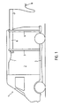
- the vehicle 1 of FIG. 1 has in its internal volume 2 a front gantry 3 and a rear gantry 4 mounted on the chassis 5 of the vehicle to slide the rail 6 of the handling device.
- a cable 7 provides power to the electric motors of this device and a remote control 8 allows the control of these motors.
- a carriage 7 is mounted movably on the rail 6 using rollers 8.
- the carriage 7 carries a winch 9 driven by an electric motor 10 and supporting at its end a lifting hook 11.
- the rail 6 also supports at its front end a geared motor 12 making it possible to drive a pulley 13 on which a chain 14 is wound.
- the chain 14 also passes around a second pulley 15 mounted idly at the rear end of the rail 6 and the two ends of this chain are fixed to the carriage 7, for example at the location of the axes of the rollers 8.
- the upper strand 16 of the chain 14 carries a front stop 17 and a rear stop 18 arranged to cooperate respectively with a stop 19 mounted on the gantry 3 and a stop 20 mounted on the gantry 4.
- the stops 17 and 18 are for example constituted lugs fixed transversely to the chain and capable of engaging in slots 21 of the stops 18 and 19.
- FIG. 2a represents the rail 6 completely tucked inside the space 2 of the vehicle 1 with the carriage 7 at the front end of the rail.
- the stop 18 of the chain 14 is engaged in the slot 21 of the stop 20.
- the device thus arrives in the position of FIG. 2c with the rail 6 extended as far as possible from the vehicle and the carriage 7 in abutment at the end of the rail.
- the movement can be interrupted at any time before the maximum stroke.
- An object to be loaded inside the vehicle 1 can then be lifted using the winch 9.
- the pulley 13 is then driven in the opposite direction, that is to say in the direction of the arrow F3, to cause the carriage and the rail to return to the interior of the vehicle.
- the carriage 7 begins to move towards the front of the rail 6, while the stops 17 and 18 move towards the rear in the direction of the arrow F4.
- the rail 6 remains stationary relative to the supporting structure.
- the stop 18 then enters the slot 21 of the stop 20 thus securing the chain 14 with the supporting structure.
- the rail 6 then begins to enter the interior of the vehicle while the carriage 7 continues its movement on the rail towards the front of the latter.
- the load can then be deposited at any point inside the vehicle after which, by continuing to rotate the pulley 13 in the direction of arrow F3, the rail is once again completely inside the vehicle in the position shown in Figure 2a.
- stops 17 and 18 can be reduced to a single one subject to suitable spacing of the stops 19 and 20, and likewise, the stops 19 and 20 could be arranged not opposite as shown in FIGS. drawings but opposite to each other with the stops 17 and 18 arranged outside of these stops 19 and 20.
Landscapes
- Engineering & Computer Science (AREA)
- Mechanical Engineering (AREA)
- Carriers, Traveling Bodies, And Overhead Traveling Cranes (AREA)
Applications Claiming Priority (2)
| Application Number | Priority Date | Filing Date | Title |
|---|---|---|---|
| FR8914064 | 1989-10-26 | ||
| FR8914064A FR2653760A1 (fr) | 1989-10-26 | 1989-10-26 | Appareil de manutention et vehicule muni d'un tel appareil. |
Publications (2)
| Publication Number | Publication Date |
|---|---|
| EP0425389A2 true EP0425389A2 (de) | 1991-05-02 |
| EP0425389A3 EP0425389A3 (en) | 1991-12-04 |
Family
ID=9386819
Family Applications (1)
| Application Number | Title | Priority Date | Filing Date |
|---|---|---|---|
| EP19900403031 Withdrawn EP0425389A3 (en) | 1989-10-26 | 1990-10-26 | Handling apparatus and vehicle equipped with such an apparatus |
Country Status (5)
| Country | Link |
|---|---|
| EP (1) | EP0425389A3 (de) |
| AU (1) | AU6497990A (de) |
| CA (1) | CA2028583A1 (de) |
| FR (1) | FR2653760A1 (de) |
| ZA (1) | ZA908564B (de) |
Cited By (4)
| Publication number | Priority date | Publication date | Assignee | Title |
|---|---|---|---|---|
| NL1014332C2 (nl) * | 2000-02-09 | 2001-08-13 | Brandjes Franciscus E M | Hijswerktuig. |
| DE102008064314A1 (de) | 2008-12-20 | 2010-07-01 | Johannes Albrecht | Vorrichtung zur Ladehilfe für einen Kleintransporter |
| CN104514390A (zh) * | 2014-12-22 | 2015-04-15 | 上海爱登堡电梯股份有限公司 | 多台共柱安装的双层简易升降停车装置 |
| CN108706450A (zh) * | 2018-06-26 | 2018-10-26 | 合肥市春华起重机械有限公司 | 一种起重机用防撞主梁 |
Family Cites Families (7)
| Publication number | Priority date | Publication date | Assignee | Title |
|---|---|---|---|---|
| FR951413A (fr) * | 1942-01-31 | 1949-10-25 | Armin Tenner Fa | Pont roulant |
| FR1412353A (fr) * | 1960-05-24 | 1965-10-01 | Mac Gregor Comarain Sa | Dispositif perfectionné de manoeuvre pour le chargement et le déchargement des navires, des silos, des magasins ou des installations analogues |
| US3061112A (en) * | 1960-12-08 | 1962-10-30 | Lake Shore Inc | Material handling apparatus |
| DE2732256A1 (de) * | 1977-07-16 | 1979-01-25 | Kaspar Klaus | Strassenlastfahrzeug mit einem ladegeraet |
| DE3006611C2 (de) * | 1980-02-22 | 1983-12-29 | Siegfried 8922 Peiting Schuster | Antriebsmechanismus für einen Auslegerkran |
| DE3161931D1 (en) * | 1980-04-18 | 1984-02-23 | Karel Helena August Theyskens | Tower crane |
| GB2105294B (en) * | 1981-06-13 | 1984-08-01 | Jonathan James Pratt | Extensible and retractable gantry for mounting in a vehicle |
-
1989
- 1989-10-26 FR FR8914064A patent/FR2653760A1/fr not_active Withdrawn
-
1990
- 1990-10-25 AU AU64979/90A patent/AU6497990A/en not_active Abandoned
- 1990-10-25 CA CA002028583A patent/CA2028583A1/fr not_active Abandoned
- 1990-10-25 ZA ZA908564A patent/ZA908564B/xx unknown
- 1990-10-26 EP EP19900403031 patent/EP0425389A3/fr not_active Withdrawn
Cited By (6)
| Publication number | Priority date | Publication date | Assignee | Title |
|---|---|---|---|---|
| NL1014332C2 (nl) * | 2000-02-09 | 2001-08-13 | Brandjes Franciscus E M | Hijswerktuig. |
| EP1123893A1 (de) * | 2000-02-09 | 2001-08-16 | Franciscus Engelbertus Maria Brandjes | Kran |
| DE102008064314A1 (de) | 2008-12-20 | 2010-07-01 | Johannes Albrecht | Vorrichtung zur Ladehilfe für einen Kleintransporter |
| CN104514390A (zh) * | 2014-12-22 | 2015-04-15 | 上海爱登堡电梯股份有限公司 | 多台共柱安装的双层简易升降停车装置 |
| CN108706450A (zh) * | 2018-06-26 | 2018-10-26 | 合肥市春华起重机械有限公司 | 一种起重机用防撞主梁 |
| CN108706450B (zh) * | 2018-06-26 | 2020-04-03 | 合肥市春华起重机械有限公司 | 一种起重机用防撞主梁 |
Also Published As
| Publication number | Publication date |
|---|---|
| CA2028583A1 (fr) | 1991-04-27 |
| EP0425389A3 (en) | 1991-12-04 |
| AU6497990A (en) | 1991-05-02 |
| FR2653760A1 (fr) | 1991-05-03 |
| ZA908564B (en) | 1991-08-28 |
Similar Documents
| Publication | Publication Date | Title |
|---|---|---|
| EP2167251A2 (de) | Vorrichtung zur handhabung einer last, z. b. einer eisenblechspule | |
| EP2089302B1 (de) | Schuh zum stillstand eines rades und motorisierte stillstandanordnung | |
| FR2722488A1 (fr) | Pince de levage pour cylindre evide axialement a axe horizontal | |
| EP0425389A2 (de) | Handhabungsgerät und ein mit solch einem Gerät ausgerüstetes Fahrzeug | |
| LU86458A1 (fr) | Installation automatisee pour briqueter la paroi interieure d'une enceinte | |
| EP0136189B1 (de) | Vorrichtung zum Greifen von Behältern, insbesondere Lagerkassetten | |
| FR2684341A1 (fr) | Dispositif pour hisser ou retirer une echelle ou analogue sur ou a partir d'une galerie de toit d'un vehicule. | |
| FR2586667A1 (fr) | Monte-charge autoporte a bras telescopiques jumeles | |
| FR2747381A1 (fr) | Dispositif de transfert d'une charge par poussee et traction dans un meme plan | |
| EP0490798A2 (de) | Kran, insbesondere für die Handhabung | |
| FR2499020A1 (fr) | Machine destinee au banderolage automatique de piles de colis | |
| EP3791845B1 (de) | Aufnahmehalterung zum motorisierten beladen und herausziehen eines wagens, der eine krankentrage umfasst, und entsprechender krankenwagen | |
| CH650456A5 (fr) | Dispositif de transport par cable. | |
| EP0593347A1 (de) | Automatische Rückholvorrichtung für eine Verbindung an einem abtrennbaren oder ausklinkbaren Teil | |
| EP0114143A2 (de) | Selbsttätiger Lastenaufzug | |
| FR2662677A1 (fr) | Dispositif pour transporter une charge, selon une allee de derivation, entre un convoyeur a rouleaux et un poste de prise de charge par un translateur. | |
| FR2702684A1 (fr) | Dispositif pour le compactage par bobinage de fils, de feuillards ou d'éléments similaires. | |
| FR2707221A1 (fr) | Véhicule de transport d'au moins une bobine. | |
| FR2493505A1 (fr) | Appareil pour le lancement de plateaux ou cibles mobiles pour le tir sportif | |
| EP1060831A1 (de) | Werkstücktransfervorrichtung | |
| FR2783492A1 (fr) | Dispositif d'exploration sous-marine | |
| FR2491891A1 (fr) | Procede de manutention et de stockage d'objets a symetrie axiale, notamment de tourets et dispositif trans-stockeur de mise en oeuvre | |
| FR2621517A1 (fr) | Poignet de robot pour le serrage et l'emmanchement de raccords en elastomere | |
| FR2665428A1 (fr) | Dispositif permettant l'enroulement ou le deroulement mecanique de cables sur un touret dispose sur un chassis remorquable. | |
| FR2496388A1 (fr) | Dispositif pour la confection de faisceaux d'objets allonges, par exemple de cables electriques |
Legal Events
| Date | Code | Title | Description |
|---|---|---|---|
| PUAI | Public reference made under article 153(3) epc to a published international application that has entered the european phase |
Free format text: ORIGINAL CODE: 0009012 |
|
| AK | Designated contracting states |
Kind code of ref document: A2 Designated state(s): AT BE CH DE DK ES FR GB GR IT LI LU NL SE |
|
| PUAL | Search report despatched |
Free format text: ORIGINAL CODE: 0009013 |
|
| AK | Designated contracting states |
Kind code of ref document: A3 Designated state(s): AT BE CH DE DK ES FR GB GR IT LI LU NL SE |
|
| 17P | Request for examination filed |
Effective date: 19920521 |
|
| STAA | Information on the status of an ep patent application or granted ep patent |
Free format text: STATUS: THE APPLICATION IS DEEMED TO BE WITHDRAWN |
|
| 18D | Application deemed to be withdrawn |
Effective date: 19940503 |