EP0425568B1 - Appareil et procede pour faire detoner des perforateurs de puits - Google Patents
Appareil et procede pour faire detoner des perforateurs de puits Download PDFInfo
- Publication number
- EP0425568B1 EP0425568B1 EP89908717A EP89908717A EP0425568B1 EP 0425568 B1 EP0425568 B1 EP 0425568B1 EP 89908717 A EP89908717 A EP 89908717A EP 89908717 A EP89908717 A EP 89908717A EP 0425568 B1 EP0425568 B1 EP 0425568B1
- Authority
- EP
- European Patent Office
- Prior art keywords
- pressure
- reservoir
- detonating
- piston
- tubing string
- Prior art date
- Legal status (The legal status is an assumption and is not a legal conclusion. Google has not performed a legal analysis and makes no representation as to the accuracy of the status listed.)
- Expired - Lifetime
Links
Images

Classifications
-
- E—FIXED CONSTRUCTIONS
- E21—EARTH OR ROCK DRILLING; MINING
- E21B—EARTH OR ROCK DRILLING; OBTAINING OIL, GAS, WATER, SOLUBLE OR MELTABLE MATERIALS OR A SLURRY OF MINERALS FROM WELLS
- E21B43/00—Methods or apparatus for obtaining oil, gas, water, soluble or meltable materials or a slurry of minerals from wells
- E21B43/11—Perforators; Permeators
- E21B43/116—Gun or shaped-charge perforators
- E21B43/1185—Ignition systems
- E21B43/11852—Ignition systems hydraulically actuated
Definitions
- This invention relates to detonating apparatus for detonating guns, particularly tubing conveyed perforating guns, for explosively perforating the well-bore casing, or perforating guns lowered on a slick line for perforating the tubing string or drill pipe string of wells such as, for example, oil, gas, water and steam wells.
- Perforating guns containing explosive charges are frequently positioned within the casing or string of oil wells and left there, at great depth, until it is required to perforate the casing or string. While the guns are in situ, it is important that they are not inadvertently detonated due to spurious electrical signals, short pressure surges, the changes in pressure as the gun is moved down or up the well, or indeed any pressure changes caused by means other than those required to actuate the detonating apparatus.
- EPA-A-0 184 377 discloses apparatus for actuating an explosive device downhole in a borehole.
- piston 132 is first displaced by increasing well-bore pressure to seal piston 122, thus irreversibly arming the apparatus.
- Detonation is effected by reducing well-bore pressure so that piston 122, rod 120 and restraining means 108 are displaced by action of the pressure differential between the pre-pressurised nitrogen chamber 181 and external well-bore pressure, as mentioned above. Detonation is immediate.
- GB 2 194 316 A also discloses apparatus for firing perforating apparatus in a borehole.
- the tubing string pressure is initially increased to create a pressure differential which actuates release means (piston 103) to decouple the restraining means (bar 7), thus irreversibly arming the apparatus.
- the release is immediate on creation of the pressure differential between the chamber between piston 3 and stop 25, and chamber 4.
- the problem to be solved in GB 2 194 316 A and which does not arise in the present invention is how to delay detonation until the well-bore pressure is reduced to create under balanced conditions.
- the problem is overcome by initially slowing the expansion of spring 16, which drives the striker 17, by causing fluid to be forced from reservoir 46 to reservoir 47 through fluid control valves 10 incorporated in piston 11.
- a pressure differential is created across piston 11 by the force of spring 16, but this differential is not created over a period of time; it is extinguished when the piston reaches the bore enlargement 45; and it cannot be utilised in the active role of displacing the restraining means.
- detonating apparatus for detonating a gun for perforating a well bore casing or a tubing or drill string, the apparatus being for suspension respectively on a tubing string or slick line lowered down the well, and comprising a detonating pin biased towards a detonator, restraining means for restraining the pin from movement until detonation is required, pressure-actuated release means comprising displaceable means arranged for displacement to release the restraining means under the influence of a predetermined differential fluid pressure, characterised in that pressure control means are provided for causing or allowing said differential pressure to be developed within the apparatus over a period of time.
- the release of the restraining means is a) caused by, and is consequent upon, a reduction in well-bore pressure; and b) delayed for a period of time after the reduction in pressure.
- the displaceable means are fixed against movement by shear means, which are sheared when detonation is required by shear forces generated when said predetermined pressure is reached.
- a spring or other energy storage means may be provided to assist subsequent movement of said means to a position in which the retaining means are released.
- the displaceable means may be connected to a piston rod of a piston and cylinder assembly, the piston having first and second fluid reservoirs on respective sides thereof within the cylinder, and movement of the piston being caused by achievement of said differential pressure between the reservoirs.
- the pressure control means are located to allow fluid in the second reservoir to bleed through a restrictor orifice into a third, variable-volume reservoir.
- the first and second reservoirs are connected by a smaller restrictor orifice which allows fluid to flow from the second reservoir into the first reservoir to allow it to be pressurised, and to flow from the first to the second reservoir while fluid is flowing from the second to the third reservoir, but at a slower rate than the rate of flow from the second to third reservoir.
- a method of actuating detonating apparatus of the above-mentioned kind comprises allowing the fluid pressure in the first and second reservoirs to equal well bore pressure, isolating the well bore from the tubing string and reducing the pressure of the fluid in the tubing string until actuation has occurred.
- a method of actuating detonating apparatus of the above-mentioned kind comprises isolating the well bore from the tubing string, increasing the pressure in the tubing string above well bore pressure, allowing the pressure in the first and second reservoirs to reach the increased value, and then reducing the pressure in the tubing string until the actuation has occurred.
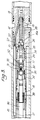
- Figures 1, 2 and 3 are sections through a plane including the longitudinal axis of successive lengths of detonating apparatus, according to the invention, for detonating tubing conveyed perforating guns.
- a tool housing 10 is joined at its upper end, i.e. at the left hand of Figure 1, to the bottom length of a tubing string (not shown) fitted with a ported sub-assembly by a screw thread 11 of an upper outer connector 12.
- the lower end of the tool 10, i.e. at the right hand of Figure 3 is joined to a perforating gun assembly 13 by a lower threaded connector 14.
- the perforating gun assembly 13 contains a perforating gun (not shown) of known kind, in which an array of outwardly-facing charges of explosive are retained, to be exploded by combination of a boosted primer cord 15 which is itself ignited by a detonator 16 of the kind which detonates on impact.
- the primer cord 15 and detonator 16 are retained on the axis of and within the lower connector 14.
- the booster is designated 16 a .
- a co-axial cylinder member 17 is screwed at its lower end to the lower connector 14 and at its upper end to an inner connector 18 which is screwed to the lower end of a piston housing 19.
- the piston housing 19 is connected through a choke housing 20 to an upper reservoir housing 21 which is in turn screwed to an upper connector 22.
- the reduced diameter upper end portion of the connector 22 is received in the recessed end portion of an upper inner connector 23 which is a sliding fit in the upper outer connector 12.
- O-ring seals are used where appropriate.
- the detonator 16 is arranged to be fired by a detonator pin 24, slidable in a central bore 25 in the lower end of the cylinder member 17, and having a pointed end 26.
- the space 27 between the detonator 16 and the detonator pin 24 is at atmospheric pressure, while the left hand (upper) end of the detonator pin 24 is vented to the pressure of the well bore outside the tool 10 by passages 28,29,30 through the lower connector 14, the cylinder member 17 and an inner sleeve 31, respectively.
- the pressure on the detonator pin 24 urges it downwards towards the detonator 16, but such movement is prevented by dogs 32, which engage in a groove in the detonator pin 24 and abut an inner face 33 of the inner sleeve 31.
- the outer cylindrical face of the sleeve 31 is a sliding fit in a bore of a collar 34 abutting the inner connector 18. The sleeve 31 is secured to the collar 34 by shear pins 35.
- a lower central rod 36 is screwed to an upper central tube 40, and a piston 41, slidable in the bore of the piston housing 19, is fastened between the rod 36 and tube 40.
- the upper central tube 40 is slidable through a central bore of the choke housing 20.
- the space within the upper chamber housing 21 between the ends of the choke housing 20 and the upper connector 22 forms an upper reservoir 42 which is divided into an upper part 42 a and a lower part 42 b by a floating piston 43.
- the piston 43 separates well fluid above it from hydraulic oil below it and allows expansion of the latter.
- the space within the piston housing 19 between the choke housing 20 and the piston 41 forms a middle reservoir 44; and the space between the inner connector 18 and the piston 41 a lower reservoir 45.
- a passage 46 through the choke housing 20 connecting together the upper reservoir 42 with the middle reservoir 44 has a central choke orifice 47 protected by filters 48 fitted one at each end of the passage 46.
- a filtered passage 49 through the lower rod 36 and a passage 50 through the upper rod 40 connect with a passage 51 in the choke housing 20, thereby permitting communication between the middle reservoir 44 and the lower reservoir 45.
- a choke orifice 52 smaller than the orifice 47, is provided in the passage 51 and is protected by a filter 53.
- a passage 54 through the upper outer connector 12 communicates with a passage 55 through the upper inner connector 23 and thence with an axial bore 56 of the upper connector 22; well pressure is thus freely communicated to the reservoir 42 a .
- a primer cord 57 runs from a position next to a booster at the bottom of the primer cord 15 to a connection at the top of the upper outer connector 12 from which a further length 58 of primer cord leads to a firing head (not shown).
- the tubing conveyed perforating guns are fired by ignition of the detonator 16 through release of the detonator pin 24. This may be achieved by various methods, two of which are now described.
- a packer is set between the well bore casing and a tubing string equipped with a tester valve. Annulus pressure above the packer is increased to open the tester valve, thus communicating lower pressure already obtaining in the upper part of the tubing string above the tester valve to the lower part of the tubing string below the tester valve; and thus also in the well bore around the detonating head.
- This reduction in ambient pressure causes a corresponding reduction in the pressure in the upper part 42 a of the upper reservoir 42 by virtue of the communication afforded by the passages 54,55 and the bore 56.
- the pressure reduction is passed on to reservoir 42 b through the floating piston 43, causing oil to bleed from the middle reservoir 44 through the passage 46 and choke 47.
- the pressure in the middle reservoir 44 falls more slowly than well bore pressure, the rate being determined by the above factors. Furthermore, the pressure in the lower reservoir 45 bleeds through the bore 50 and passage 51 even more slowly than that in the middle reservoir 44 because the choke 52 is smaller than the choke 47.
- the piston 41 is subject to a pressure differential causing an upward force thereon. The magnitude of the pressure differential slowly rises to a point where the shear pins 35 are sheared so that the piston 41 is urged upwards, drawing the lower rod 36 and the sleeve 31 with it, aided by the spring 39.
- Reduction of the tubing pressure may be achieved by running the detonating head with a DST type string and applying pressure to the annulus to open a ball valve to allow communication of the well bore in the region of the tool 10 with a lower hydrostatic pressure above the valve, as previously indicated.
- Another method of operation of the detonating head involves the use of nitrogen and the manipulation of various tester and circulating valves in the system, thereby creating the necessary pressure drops required to actuate the detonating head.
- the detonating head is run down the well on a tubing string partly filled with fluid, and equipped with a packer and tester valves.
- the tester valve is opened by the application of annulus pressure which allows the well bore around the detonating head to be pressurised by the nitrogen pressure applied to the tubing string.
- the tester valve is then closed by bleeding off the annulus, and nitrogen above the tester valve is slowly bled off at the surface, during which time the head is pressurised as previously described.
- the tester valve is opened by pressurising the annulus, the immediate pressure drop around the head causes the guns to be detonated.
- gas pressure for example nitrogen pressure
- the detonator 16 fails to go off the perforating guns may be fired by actuating the firing head at the upper end of the primer cord 58. If the guns fail to detonate the whole detonating head can be rendered safe by allowing well bore pressure to reach the atmospheric chamber below the detonating pin 24 through the route of the primer cords 58,57. It will be appreciated that the primer cords 57,58 burn out when the apparatus works normally.
- a shaped charge is interposed between the detonator or high temperature initiator (HTI) 16 and the top of the booster 16 a so that if the charge or the HTI 16 fails a metal barrier will not be breached; if the charge and the HTI 16 do detonate then it may be assumed that perforation has occurred. This arrangement prevents the destruction of components any further back.
- HTI high temperature initiator
- differential pressure firing system has been described as run above the guns, it may also run below the guns.
- the system may be used to perforate a tubing or drill pipe string by running it down the string on a slick line, and increasing the pressure in the string to cause detonation.
Landscapes
- Life Sciences & Earth Sciences (AREA)
- Engineering & Computer Science (AREA)
- Geology (AREA)
- Mining & Mineral Resources (AREA)
- Physics & Mathematics (AREA)
- Environmental & Geological Engineering (AREA)
- Fluid Mechanics (AREA)
- General Life Sciences & Earth Sciences (AREA)
- Geochemistry & Mineralogy (AREA)
- Investigating Strength Of Materials By Application Of Mechanical Stress (AREA)
- Actuator (AREA)
Abstract
Claims (11)
- Dispositif de mise à feu pour faire exploser une charge (13) pour perforer un tubage de puits de forage ou une colonne de production ou une garniture de forage, le dispositif étant prévu pour être suspendu respectivement sur une colonne de production ou une tige polie abaissée dans le puits, et comprenant une broche de mise à feu (24) assujettie vers un détonateur (16), des moyens de retenue (32) pour empêcher la broche (24) de se déplacer jusqu'à ce que soit exigée la mise à feu, des moyens de libération à commande par pression (36,41) comprenant des moyens déplaçables (31) agencés pour être déplacés pour libérer les moyens de retenue (32) sous l'influence d'une différence de pression de fluide prédéterminée, caractérisé en ce qu'il est prévu des moyens de commande de pression (47,52) pour provoquer ou permettre le développement de cette différence de pression à l'intérieur du dispositif sur une certaine période de temps.
- Dispositif selon la revendication 1, dans lequel les moyens de libération à commande par pression (36,41) comprennent un ensemble de piston (41) et de cylindre (19), le piston (41) ayant des premier et deuxième réservoirs de fluide (45,44) de part et d'autre du piston à l'intérieur du cylindre (19), le mouvement du piston (41) étant provoqué par l'établissement d'une différence de pression entre les réservoirs (45,44).
- Dispositif selon la revendication 2, dans lequel les moyens de commande de pression (47,52) sont agencés pour laisser le fluide à l'intérieur du deuxième réservoir (44) passer à travers un orifice d'étranglement dans un troisième réservoir à volume variable (42).
- Dispositif selon la revendication 3, dans lequel les premier et deuxième réservoirs (45,44) sont reliés entre eux par un orifice d'étranglement (52) plus petit, qui permet au fluide de passer du deuxième réservoir (44) dans le premier réservoir (45) afin de le mettre en pression, tandis que le fluide passe du deuxième réservoir (44) dans le troisième réservoir (42), mais à un débit plus faible que le débit de fluide passant du deuxième (44) au troisième réservoir (42).
- Dispositif selon l'une des revendications 3 ou 4, dans lequel le troisième réservoir à volume variable (42) comprend un cylindre (22) et un piston libre (43), la position d'une face de ce piston à l'intérieur du cylindre (22) définissant le volume du réservoir, et l'autre face du piston étant soumise à la pression du puits de forage.
- Dispositif selon l'une des revendications précédentes, dans lequel le mouvement des moyens déplaçables (31) est empêché par des moyens cisaillables (35) qui sont cisaillés lors de l'explosion par les forces de cisaillement produites lorsqu'est atteinte la différence de pression prédéterminée.
- Dispositif selon l'une des revendications précédentes, dans lequel les moyens déplaçables (31) sont assujettis à des moyens élastiques (39) pour faciliter le mouvement ultérieur de ces moyens (31) jusqu'à une position dans laquelle les moyens de retenue (32) sont libérés.
- Dispositif selon l'une des revendications précédentes, dans lequel les moyens de retenue (32) comprennent des éléments de verrouillage (32) pouvant coopérer avec la broche de mise à feu (24) et dans lequel les moyens déplaçables (31) comportent un élément déplaçable (31) pour maintenir en position les éléments de verrouillage (32).
- Procédé pour délencher un dispositif de mise à feu selon l'une des revendications 2 à 5 ou selon l'une des revendications 6, 7 ou 8 comme en dépendant, consistant à laisser la pression de fluide dans les premier et deuxième réservoirs (45,44) égaler la pression du puits, isoler le puits de la colonne de production et réduire la pression de fluide dans la colonne de production jusqu'au déclenchement du dispositif.
- Procédé pour déclencher un dispositif de mise à feu selon l'une des revendications 2 à 5 ou selon l'une des revendications 6, 7 ou 8 comme en dépendant, consistant à isoler le puits de la colonne de production, à augmenter la pression dans la colonne de production à une valeur supérieure à celle de la pression dans le puits, à laisser la pression dans les premier et deuxième réservoirs (45,44) atteindre cette valeur augmentée, et à réduire ensuite la pression dans la colonne de production jusqu'au déclenchement du dispositif.
- Procédé selon la revendication 10, dans lequel la pression dans la colonne de production est augmentée par une pressurisation avec un gaz.
Applications Claiming Priority (3)
| Application Number | Priority Date | Filing Date | Title |
|---|---|---|---|
| GB888817178A GB8817178D0 (en) | 1988-07-19 | 1988-07-19 | Apparatus for detonating well casing perforating guns |
| GB8817178 | 1988-07-19 | ||
| PCT/GB1989/000831 WO1990001103A1 (fr) | 1988-07-19 | 1989-07-19 | Appareil et procede pour faire detoner des perforateurs de puits |
Publications (2)
| Publication Number | Publication Date |
|---|---|
| EP0425568A1 EP0425568A1 (fr) | 1991-05-08 |
| EP0425568B1 true EP0425568B1 (fr) | 1995-01-11 |
Family
ID=10640728
Family Applications (1)
| Application Number | Title | Priority Date | Filing Date |
|---|---|---|---|
| EP89908717A Expired - Lifetime EP0425568B1 (fr) | 1988-07-19 | 1989-07-19 | Appareil et procede pour faire detoner des perforateurs de puits |
Country Status (4)
| Country | Link |
|---|---|
| US (1) | US5167282A (fr) |
| EP (1) | EP0425568B1 (fr) |
| GB (1) | GB8817178D0 (fr) |
| WO (1) | WO1990001103A1 (fr) |
Families Citing this family (14)
| Publication number | Priority date | Publication date | Assignee | Title |
|---|---|---|---|---|
| WO1993020330A1 (fr) * | 1992-03-30 | 1993-10-14 | Phoenix Petroleum Services Ltd. | Appareil de detonation des perforateurs de puits |
| US5301755A (en) * | 1993-03-11 | 1994-04-12 | Halliburton Company | Air chamber actuator for a perforating gun |
| US5490563A (en) * | 1994-11-22 | 1996-02-13 | Halliburton Company | Perforating gun actuator |
| US5551520A (en) * | 1995-07-12 | 1996-09-03 | Western Atlas International, Inc. | Dual redundant detonating system for oil well perforators |
| US5709265A (en) | 1995-12-11 | 1998-01-20 | Weatherford/Lamb, Inc. | Wellbore window formation |
| US5636692A (en) * | 1995-12-11 | 1997-06-10 | Weatherford Enterra U.S., Inc. | Casing window formation |
| US5791417A (en) | 1995-09-22 | 1998-08-11 | Weatherford/Lamb, Inc. | Tubular window formation |
| US5992289A (en) * | 1998-02-17 | 1999-11-30 | Halliburton Energy Services, Inc. | Firing head with metered delay |
| US7331392B2 (en) * | 2005-08-06 | 2008-02-19 | G. Bosley Oilfield Services Ltd. | Pressure range delimited valve |
| US7516783B2 (en) * | 2007-06-20 | 2009-04-14 | Petroquip Energy Services, Llp | Double pin connector and hydraulic connect with seal assembly |
| US8006779B2 (en) * | 2009-02-18 | 2011-08-30 | Halliburton Energy Services, Inc. | Pressure cycle operated perforating firing head |
| US8844625B2 (en) * | 2011-11-01 | 2014-09-30 | Baker Hughes Incorporated | Perforating gun spacer |
| EP3658748A4 (fr) * | 2017-07-25 | 2021-04-28 | Hunting Titan, Inc. | Retard hydraulique actionné par la sortie énergétique d'un pistolet perforateur |
| US12012829B1 (en) | 2020-02-27 | 2024-06-18 | Reach Wireline, LLC | Perforating gun and method of using same |
Family Cites Families (6)
| Publication number | Priority date | Publication date | Assignee | Title |
|---|---|---|---|---|
| US4650010A (en) * | 1984-11-27 | 1987-03-17 | Halliburton Company | Borehole devices actuated by fluid pressure |
| NO854739L (no) * | 1984-11-27 | 1986-05-28 | Vann Systems Halliburton Co | Fluidumtrykk-desarmerbar borehull-innretning. |
| US4629001A (en) * | 1985-05-28 | 1986-12-16 | Halliburton Company | Tubing pressure operated initiator for perforating in a well borehole |
| US4678044A (en) * | 1986-03-31 | 1987-07-07 | Halliburton Company | Tubing pressure operated initiator for perforating in a well borehole |
| AU7585487A (en) * | 1986-06-19 | 1988-01-12 | Phoenix Petroleum Services | Improvements relating to detonating heads |
| US4770246A (en) * | 1986-08-11 | 1988-09-13 | Dresser Industries, Inc. | Method and apparatus for firing borehole perforating apparatus |
-
1988
- 1988-07-19 GB GB888817178A patent/GB8817178D0/en active Pending
-
1989
- 1989-07-19 WO PCT/GB1989/000831 patent/WO1990001103A1/fr not_active Ceased
- 1989-07-19 EP EP89908717A patent/EP0425568B1/fr not_active Expired - Lifetime
-
1992
- 1992-03-30 US US07/860,562 patent/US5167282A/en not_active Expired - Fee Related
Also Published As
| Publication number | Publication date |
|---|---|
| GB8817178D0 (en) | 1988-08-24 |
| EP0425568A1 (fr) | 1991-05-08 |
| US5167282A (en) | 1992-12-01 |
| WO1990001103A1 (fr) | 1990-02-08 |
Similar Documents
| Publication | Publication Date | Title |
|---|---|---|
| US4554981A (en) | Tubing pressurized firing apparatus for a tubing conveyed perforating gun | |
| US5490563A (en) | Perforating gun actuator | |
| EP0092476B1 (fr) | Technique de perforation de puits avec dispositif de mise à feu contrôlé par pression | |
| US5603384A (en) | Universal perforating gun firing head | |
| US4969525A (en) | Firing head for a perforating gun assembly | |
| EP0481571B1 (fr) | Dispositif pour perforer un puits | |
| US4544034A (en) | Actuation of a gun firing head | |
| US4616718A (en) | Firing head for a tubing conveyed perforating gun | |
| US5680905A (en) | Apparatus and method for perforating wellbores | |
| US4650010A (en) | Borehole devices actuated by fluid pressure | |
| US4560000A (en) | Pressure-activated well perforating apparatus | |
| US5301755A (en) | Air chamber actuator for a perforating gun | |
| EP0425568B1 (fr) | Appareil et procede pour faire detoner des perforateurs de puits | |
| US5890539A (en) | Tubing-conveyer multiple firing head system | |
| EP0319321B1 (fr) | Dispositif de mise à feu pour un perforateur guidé par un tube et procédé pour perforer | |
| US5062485A (en) | Variable time delay firing head | |
| CA1284768C (fr) | Mecanisme de mise a feu pour perforateur a balles sous tubage | |
| US4690227A (en) | Gun firing head | |
| US4917189A (en) | Method and apparatus for perforating a well | |
| US3530948A (en) | Perforator | |
| US6085843A (en) | Mechanical shut-off valve | |
| GB2138925A (en) | Firing of well perforation guns | |
| CA1259561A (fr) | Dispositifs sur forage neutralises par pression fluidique | |
| GB2150267A (en) | Pressure fired perforating gun for cased wells | |
| WO1993020330A1 (fr) | Appareil de detonation des perforateurs de puits |
Legal Events
| Date | Code | Title | Description |
|---|---|---|---|
| PUAI | Public reference made under article 153(3) epc to a published international application that has entered the european phase |
Free format text: ORIGINAL CODE: 0009012 |
|
| 17P | Request for examination filed |
Effective date: 19901231 |
|
| AK | Designated contracting states |
Kind code of ref document: A1 Designated state(s): DE FR GB IT NL |
|
| 17Q | First examination report despatched |
Effective date: 19920722 |
|
| RBV | Designated contracting states (corrected) |
Designated state(s): GB |
|
| REG | Reference to a national code |
Ref country code: DE Ref legal event code: 8566 |
|
| GRAA | (expected) grant |
Free format text: ORIGINAL CODE: 0009210 |
|
| AK | Designated contracting states |
Kind code of ref document: B1 Designated state(s): GB |
|
| PLBE | No opposition filed within time limit |
Free format text: ORIGINAL CODE: 0009261 |
|
| STAA | Information on the status of an ep patent application or granted ep patent |
Free format text: STATUS: NO OPPOSITION FILED WITHIN TIME LIMIT |
|
| 26N | No opposition filed | ||
| REG | Reference to a national code |
Ref country code: GB Ref legal event code: IF02 |
|
| PGFP | Annual fee paid to national office [announced via postgrant information from national office to epo] |
Ref country code: GB Payment date: 20030716 Year of fee payment: 15 |
|
| PG25 | Lapsed in a contracting state [announced via postgrant information from national office to epo] |
Ref country code: GB Free format text: LAPSE BECAUSE OF NON-PAYMENT OF DUE FEES Effective date: 20040719 |
|
| GBPC | Gb: european patent ceased through non-payment of renewal fee |
Effective date: 20040719 |