EP0425767B1 - Szintillationszählsystem zur lokalen Messung von radioaktiven Proben in einer mit mehreren Schächten versehenen Platte - Google Patents
Szintillationszählsystem zur lokalen Messung von radioaktiven Proben in einer mit mehreren Schächten versehenen Platte Download PDFInfo
- Publication number
- EP0425767B1 EP0425767B1 EP90114090A EP90114090A EP0425767B1 EP 0425767 B1 EP0425767 B1 EP 0425767B1 EP 90114090 A EP90114090 A EP 90114090A EP 90114090 A EP90114090 A EP 90114090A EP 0425767 B1 EP0425767 B1 EP 0425767B1
- Authority
- EP
- European Patent Office
- Prior art keywords
- sample
- pmt
- pulses
- wells
- row
- Prior art date
- Legal status (The legal status is an assumption and is not a legal conclusion. Google has not performed a legal analysis and makes no representation as to the accuracy of the status listed.)
- Expired - Lifetime
Links
- 238000003345 scintillation counting Methods 0.000 title claims description 8
- 238000012625 in-situ measurement Methods 0.000 title claims description 5
- 230000002285 radioactive effect Effects 0.000 title claims description 5
- 238000000034 method Methods 0.000 claims description 16
- 239000007788 liquid Substances 0.000 claims description 14
- 238000012545 processing Methods 0.000 claims description 8
- 239000011324 bead Substances 0.000 claims description 6
- 239000002245 particle Substances 0.000 claims description 6
- 239000007787 solid Substances 0.000 claims description 6
- 230000004044 response Effects 0.000 claims description 5
- 239000011159 matrix material Substances 0.000 claims description 3
- 238000003127 radioimmunoassay Methods 0.000 claims description 3
- IQFYYKKMVGJFEH-OFKYTIFKSA-N 1-[(2r,4s,5r)-4-hydroxy-5-(tritiooxymethyl)oxolan-2-yl]-5-methylpyrimidine-2,4-dione Chemical compound C1[C@H](O)[C@@H](CO[3H])O[C@H]1N1C(=O)NC(=O)C(C)=C1 IQFYYKKMVGJFEH-OFKYTIFKSA-N 0.000 claims description 2
- 230000002441 reversible effect Effects 0.000 claims description 2
- 230000006335 response to radiation Effects 0.000 claims 1
- IAUKWGFWINVWKS-UHFFFAOYSA-N 1,2-di(propan-2-yl)naphthalene Chemical compound C1=CC=CC2=C(C(C)C)C(C(C)C)=CC=C21 IAUKWGFWINVWKS-UHFFFAOYSA-N 0.000 description 4
- 238000001514 detection method Methods 0.000 description 4
- BBEAQIROQSPTKN-UHFFFAOYSA-N pyrene Chemical compound C1=CC=C2C=CC3=CC=CC4=CC=C1C2=C43 BBEAQIROQSPTKN-UHFFFAOYSA-N 0.000 description 4
- YXFVVABEGXRONW-UHFFFAOYSA-N Toluene Chemical compound CC1=CC=CC=C1 YXFVVABEGXRONW-UHFFFAOYSA-N 0.000 description 3
- JJWKPURADFRFRB-UHFFFAOYSA-N carbonyl sulfide Chemical compound O=C=S JJWKPURADFRFRB-UHFFFAOYSA-N 0.000 description 3
- BPQQTUXANYXVAA-UHFFFAOYSA-N Orthosilicate Chemical compound [O-][Si]([O-])([O-])[O-] BPQQTUXANYXVAA-UHFFFAOYSA-N 0.000 description 2
- WUKWITHWXAAZEY-UHFFFAOYSA-L calcium difluoride Chemical compound [F-].[F-].[Ca+2] WUKWITHWXAAZEY-UHFFFAOYSA-L 0.000 description 2
- 229910001634 calcium fluoride Inorganic materials 0.000 description 2
- 238000004113 cell culture Methods 0.000 description 2
- GVEPBJHOBDJJJI-UHFFFAOYSA-N fluoranthrene Natural products C1=CC(C2=CC=CC=C22)=C3C2=CC=CC3=C1 GVEPBJHOBDJJJI-UHFFFAOYSA-N 0.000 description 2
- 230000006870 function Effects 0.000 description 2
- 238000005259 measurement Methods 0.000 description 2
- 238000012986 modification Methods 0.000 description 2
- 230000004048 modification Effects 0.000 description 2
- 230000003287 optical effect Effects 0.000 description 2
- 230000008569 process Effects 0.000 description 2
- 230000005855 radiation Effects 0.000 description 2
- 238000001228 spectrum Methods 0.000 description 2
- 238000012360 testing method Methods 0.000 description 2
- 229910052727 yttrium Inorganic materials 0.000 description 2
- VWQVUPCCIRVNHF-UHFFFAOYSA-N yttrium atom Chemical compound [Y] VWQVUPCCIRVNHF-UHFFFAOYSA-N 0.000 description 2
- QKLPIYTUUFFRLV-YTEMWHBBSA-N 1,4-bis[(e)-2-(2-methylphenyl)ethenyl]benzene Chemical compound CC1=CC=CC=C1\C=C\C(C=C1)=CC=C1\C=C\C1=CC=CC=C1C QKLPIYTUUFFRLV-YTEMWHBBSA-N 0.000 description 1
- OKTJSMMVPCPJKN-NJFSPNSNSA-N Carbon-14 Chemical compound [14C] OKTJSMMVPCPJKN-NJFSPNSNSA-N 0.000 description 1
- 238000004458 analytical method Methods 0.000 description 1
- 230000009286 beneficial effect Effects 0.000 description 1
- 238000010586 diagram Methods 0.000 description 1
- 230000000694 effects Effects 0.000 description 1
- 230000007246 mechanism Effects 0.000 description 1
- 239000000203 mixture Substances 0.000 description 1
- 239000002904 solvent Substances 0.000 description 1
- 238000004611 spectroscopical analysis Methods 0.000 description 1
- 230000002459 sustained effect Effects 0.000 description 1
- 238000012546 transfer Methods 0.000 description 1
Images

Classifications
-
- G—PHYSICS
- G01—MEASURING; TESTING
- G01T—MEASUREMENT OF NUCLEAR OR X-RADIATION
- G01T1/00—Measuring X-radiation, gamma radiation, corpuscular radiation, or cosmic radiation
- G01T1/16—Measuring radiation intensity
- G01T1/20—Measuring radiation intensity with scintillation detectors
- G01T1/204—Measuring radiation intensity with scintillation detectors the detector being a liquid
-
- G—PHYSICS
- G01—MEASURING; TESTING
- G01T—MEASUREMENT OF NUCLEAR OR X-RADIATION
- G01T1/00—Measuring X-radiation, gamma radiation, corpuscular radiation, or cosmic radiation
- G01T1/29—Measurement performed on radiation beams, e.g. position or section of the beam; Measurement of spatial distribution of radiation
- G01T1/2914—Measurement of spatial distribution of radiation
-
- G—PHYSICS
- G01—MEASURING; TESTING
- G01T—MEASUREMENT OF NUCLEAR OR X-RADIATION
- G01T7/00—Details of radiation-measuring instruments
- G01T7/08—Means for conveying samples received
Definitions
- the present invention relates generally to radiometric analysis systems and, more particularly, to such systems which utilize liquid scintillators for detecting radiation from radioactive samples.
- the present invention relates to a method for in-situ measurement of the radioactivity of multiple beta-emitting samples while the samples are in a multiple-well sample tray, and to an apparatus for carrying out same, the special features of which are presented in in the preamble clause of respective independent claims 1 and 9. It is also known from reference US-A-4005292 a method and apparatus comprising similar features as described above.
- U.S. Patent No. 4,298,796 describes a system for measuring the radioactivity of such samples by first removing the samples from the tray or plate in which the cells are cultured, resulting in the transfer of the samples to a filter mat. The filter mat is then enclosed in a container which includes a liquid scintillator, and the individual samples are measured while disposed within the container.
- the only presently known commercial version of this system utilizes two photomultiplier tubes for detecting the light scintillations attributable to each individual sample, so that the sample can be measured using the well known coincidence detection technique commonly used in liquid scintillation spectrometers.
- an array of sample tubes each containing a liquid sintillation sample are placed at a fixed distance located above an array of photo detectors which are positioned in the array with overlapping fields of view to produce electrical pulses in response to light sintillations.
- the array of photo detectors are positioned below the samples at a predetermined distance and fixed to the sample analyzing device by means of a set of coil springs, with a collimator member interposed in between the samples and the photo detectors.
- the collimator is necessary in order to prevent cross talk between adjacent samples.
- a sorting means is provided for processing the electrical signals in order to attribute each of the output signals to a particular one of the samples.
- Another important object of this invention is to provide an improved scintillation counting system which is capable of simultaneously counting multiple samples directly in the multiple-well plate in which the samples are prepared, thereby attaining high sample throughput rates.
- a still further object of this invention is to provide such an improved scintillation counting system which uses only a single photomultiplier tube to measure the radioactivity of each sample.
- the foregoing objectives are realized by providing a method for in-situ measurement of the radioactivity of multiple beta-emitting samples while the samples are in a multiple-well sample plate comprising the steps set out in independent claim 1.
- the present invention also provides an apparatus for carrying out the method comprising the features set out in claim 9.
- the foregoing objectives are realized by providing a system for in-situ measurement of the radioactivity of multiple samples while the samples are in a multiple-well sample plate in which the samples are cultured or otherwise prepared.
- a scintillator is provided in each sample-containing well, and multiple photomultiplier tubes are positioned adjacent the sample wells containing the scintillator for simultaneously measuring the radioactivity of multiple samples. Only a single photomultiplier tube senses the scintillations from each well and converts the sensed scintillations into corresponding electrical pulses.
- the electrical pulses from each photomultiplier tube are processed to discriminate between pulses attributable to sample events within the wells and pulses attributable to non-sample events such as photomultiplier tube noise.
- the discrimination is effected by determining whether a selected number of electrical pulses occur within a prescribed time interval, with the occurrence of the selected number of pulses within the prescribed time interval signifying a sample event.
- the electrical pulses attributable to sample events are supplied to a pulse analyzer which evaluates the number and energy level of the pulses attributed to each sample.
- FIG. 1 there is shown a scintillation spectrometer for measuring the radioactivity levels of multiple samples contained in a sample plate 10 having multiple sample wells S1-S96.
- the wells are arranged in eight rows, each containing twelve wells.
- the plate 10 is loaded by a conveyor 11 into a light-tight counting chamber 12 via a conventional shutter mechanism 13 which is opened and closed to permit ingress and egress of successive sample plates.
- the multi-well plate 10 is indexed beneath two rows 14 and 15 of photomultiplier tubes (PMT's) P.
- the PMT's P are arranged in two rows, each containing six PMT's, for counting samples in a 96-well plate forming an 8 x 12 matrix of sample wells.
- the two rows of PMT's P1-P6 and P7-P12 are staggered relative to each other so that the PMT's in one row are aligned with alternate wells in one of the twelve-well rows, while the PMT's in the other row are aligned with the intervening wells in an adjacent twelve-well row. Consequently, after any given twelve-well row has been passed under both rows of PMT's P-1-P-12, the samples in all twelve wells in that row will have been counted.
- the multiple-well sample plate is periodically indexed beneath the twelve PMT's so that each sample well is eventually positioned directly beneath one of the PMT's for counting.
- the plate contains eight rows of sample wells S1-S12, S13-S24, S25-S36, S37-S48, S49-S60, S61-S72, S73-S84 and S85-S96, the plate is initially positioned with wells S2, S4, S6, S8 and S10 in the first row aligned with the second row of six PMT's P7-P12.
- the tray is indexed to advance the tray by one row, so that wells S1, S3, S5, S7, S9 and S11 in the first row aligned with the first row of PMT's P1-P6, and wells S2, S4, S6, S8, S10 and S12 in the second row aligned second row of PMT's P7-P12.
- the use of two rows of PMT's to count a single row of samples is beneficial in that it permits the use of larger PMT's than would be possible if all the PMT's were in a single row. In general, the larger PMT will provide better efficiency because it is capable of detecting more photons. With the arrangement illustrated, two rows of half-inch PMT's can be used to count the samples in a standard 96-well plate with only nine indexing steps.
- Each of the 96 sample wells is provided with a scintillator that converts radiation such as beta particles into corresponding light pulses.
- the scintillator may be provided in a variety of different forms.
- a predetermined amount of a liquid scintillation cocktail is placed in each sample well before the sample plate is loaded into the counting chamber 12. Then, as the radionuclide in the sample decays, the resulting beta particles energize the fluor contained within the liquid scintillation cocktail.
- the fluor converts the energy from the beta particles into optical events which are detected by the corresponding PMT.
- the PMT in turn produces an electrical output signal corresponding to the detected optical events, and this signal is processed electronically to determine the radioactivity level of the sample.
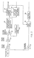
- the output of each of the twelve PMT's is passed through a pair of amplifiers 16 and 17 to a comparator 18 which serves as a single photon detector. More specifically, the comparator 18 receives a reference voltage from a single-photon threshold reference source 19, and produces an output pulse only when the input signal from the PMT exceeds the threshold set by the reference voltage. These output pulses from the comparator 18, sometimes referred to as "singles" pulses, indicate that the amplitude of the detected pulse is large enough to represent at least a single photoelectron.
- the output pulses from the comparator 18 are fed to a burst pulse counter 20, which functions to sum the "singles" pulses received from the comparator.
- the counter 20 sums the received pulses during a time interval set by a timer 21 which is started by the first pulse in each scintillation burst.
- each beta particle produces a burst of photons in the liquid scintillator, and thus each "scintillation" attributable to a single beta particle is actually a burst of scintillations produced within a brief time interval.
- the duration of the time interval is a function of the scintillation decay constant of the particular scintillator used.
- Each photon is capable of causing the generation of a separate electrical pulse from the PMT, and thus the PMT converts each burst of scintillations into a corresponding burst of electrical pulses.
- a pulse generation circuit 22 produces a set of pulses in response to a sustained output from the comparator 18. This set of pulses is supplied to the pulse counter 20 so that the corresponding PMT output will be treated as a sample event.
- the counter 20 Whenever the counter 20 receives two or more pulses within the time period set by the timer 21, the counter produces an output signal which enables an analog-to-digital (A/D) converter 30.
- the converter 30 also receives the PMT output via an amplifier 31 and, when the converter is enabled, it supplies the digital counterpart of the analog output of the PMT to the memory 32 of a conventional multi-channel analyzer.
- the noise pulses produced by a PMT are typically single pulses rather than bursts of pulses.
- the signal processing system can discriminate between noise pulses and pulses attributable to sample events by determining whether any given pulse is part of a pulse burst. If the pulse in question is determined to originate in a burst caused by a sample decay event, the pulse burst is counted as a single sample event and is passed along to a pulse analyzer which determines the energy level of the pulse burst. If the pulse is deemed to originate from a noise event, the pulse is attributed to noise and ignored.
- the signal processing system must detect at least two consecutive pulses within a prescribed time interval in order for any given pulse to be attributed to a sample event.
- the timer 21 enables the burst counter 20 to count consecutive pulses for a preselected time period.
- This time period is adjustable within a selected range, e.g., within the range of about 50 to about 225 nanoseconds, depending upon the particular scintillator utilized in the sample wells. When excited, scintillators release their energy over a period of time which varies with the scintillator.
- This time period is known as the "decay constant” or “decay time.” Scintillators are generally classified as being “fast,” indicating that the absorbed energy is released very quickly, or “slow", which indicates that the energy is given up over an extended period. As a consequence, the time period set by the timer 21 can be shorter for "fast" scintillators than for "slow" scintillators. In general, the timer should be set to a time period that is approximately three to four times the scintillation decay constant of the scintillator. For example, if a scintillator has a decay constant of 50 nanoseconds, the timer 21 is set to about 175 nanoseconds, which is 3.5 times the decay constant. (The rate of photons emitted by the scintillator in response to a single decay event is reduced by 50% in each time interval prescribed by the scintillation decay constant.)
- Noise pulses originating in the PMT's are single photoelectron thermal events, and thus are not detected as sample events. Moreover, the decay time of such noise pulses at the anode of the PMT (as determined by the PMT dynode chain circuit) can be limited to 10 to 15 nanoseconds, and thus such pulses are not likely to be detected as part of a pulse burst from a sample. Tube noise pulses are usually by far the most frequent background event, and thus discriminating between the pulse bursts produced by sample events and the single pulses from tube noise is particularly valuable. For example, tube noise pulses may occur at a rate of 500 to 1000 per minute, while cosmic rays typically occur at a rate of only 10 to 40 per minute.
- the signal processing circuitry can normally distinguish consecutive pulses in a burst as separate pulses only when the pulses are spaced apart by more than about ten nanoseconds. This is sometimes referred to as the "pulse pair resolution time.” Many of the scintillators normally used in liquid scintillation spectrometry are extremely fast, producing pulse bursts in which the component pulses are spaced apart by less than ten nanoseconds. Scintillators with longer decay constants, preferably at least 15 nanoseconds, are preferred. In general, most of the light emitted by a scintillator in response to a single decay event occurs in three or four decay constants. Thus, when a scintillator having a decay constant of 15 nanoseconds is utilized, setting the timer to 55 nanoseconds will permit multiple component pulses of a single burst to be detected.
- liquid scintillation cocktail suitable for use in this invention contains diisopropyl naphthalene as the solvent and a fluor such as pyrene.
- a preferred cocktail of this type has 0.0992 gram of pyrene in 15 milliliters of diisopropyl naphthalene.
- this cocktail was labeled with 38,100 DPM carbon-14 toluene, and 500 microliters was pipetted into a sample well and counted with the pulse deteotion system of FIG. 3 circuit. The resulting spectrum had the characteristic shape of a beta spectrum, and the counting efficiency was 72%.
- Another liquid scintillation cocktail suitable for use in this invention is a mixture of diisopropyl naphthalene and P-bis(O-methyl styryl)-benzene, referred to hereinafter as "bisMSB.”
- a preferred cocktail of this type contains one gram of bisMSB for each liter of diisopropyl naphthalene. In a test, this cocktail was labeled with tritiated thymidine and counted with the pulse detection circuit of FIG. 3. A counting efficiency of 7.87% was obtained.
- the scintillator can be a solid rather than a liquid.
- scintillator beads of cerium-doped yttrium silicate or calcium fluoride can be used in a scintillation proximity radioimmunoassay carried out in a multiple-well sample tray, as described in more detail in the assignee's copending U.S. patent application Serial No. 444,297 filed December 1, 1989 for "Scintillation Proximity Radioimmunoassay Using Solid Scintillator Support Body.”
- the beads of scintillator are extremely small, e.g., 10 microns, and thus numerous beads are contained in each sample well.
- the doped yttrium silicate has a scintillation decay constant of 56 nanoseconds
- calcium fluoride has a scintillation decay constant of 1000 nanoseconds.
- Solid scintillators may also be used to form the walls of the sample wells, or just portions of the walls such as the bottoms of the wells, rather than being used in the form of beads. Alternatively, a stable layer of solid scintillator may be deposited on the bottoms of the sample wells. Yet another form of scintillator suitable for use in this invention is reversible between the sold and liquid states.
Landscapes
- Physics & Mathematics (AREA)
- Health & Medical Sciences (AREA)
- Life Sciences & Earth Sciences (AREA)
- General Physics & Mathematics (AREA)
- High Energy & Nuclear Physics (AREA)
- Molecular Biology (AREA)
- Spectroscopy & Molecular Physics (AREA)
- Measurement Of Radiation (AREA)
Claims (17)
- Ein Verfahren zur Messung der Radioaktivität von mehreren beta-emittierenden Proben an Ort und Stelle, während die Proben (S1...Sn) in einem Probentablett (10) mit mehreren Schächten sind, wobei das genannte Verfahren die Schritte umfaßt:
Bereitstellen eines Szintillators in jedem eine Probe enthaltenden Schacht (S1...Sn) zum Erzeugen von Lichtimpulsen in Reaktion auf die genannten Betaemissionen;
Anordnen mehrerer Sekundärelektronenvervielfacherröhren (PMTs) (P1-P12) in einer Matrix nahe den genannten den genannten Szintillator enthaltenden Probenschächten, die zur gleichzeitigen Messung der Radioaktivität von mehreren Proben mit den genannten PMT's, die die Szintillationen von den genannten Szintillatoren erfassen und die erfaßten Szintillationen in entsprechende elektrische Impulse umwandeln;
Verarbeiten der elektrischen Impulse von jeder Sekundärelektronenvervielfacherröhre, um daraus ein Probenereignis zu bestimmen; und
Zuführen nur der elektrischen Impulse, die Probenereignissen zuzuordnen sind, zu einem Impulsanalysator,
gekennzeichnet durch
Positionieren der PMT's den Enden der genannten Probenschächte (S1...Sn) nahe benachbart derart, daß nur ein einzelner PMT die Szintillationen von jedem entsprechenden Schacht erfaßt, wobei die Vorderseite von jedem PMT, im wesentlichen das gesamte Ende des entsprechenden Probenschachtes überdeckt; und daß
der genannte Schritt zum Bestimmen eines Probenereignisses das Unterscheiden zwischen Impulsen, die Probenereignissen in den genannten Schächten zuzuordnen sind, und Impulsen enthält, die Nicht-Probenereignissen, wie Sekundärelektronenvervielfacherröhren-Rauschen, zuzuordnen sind, wobei die genannte Unterscheidung durchgeführt wird, indem bestimmt wird, ob eine ausgewählte Anzahl von elektrischen Impulsen innerhalb eines vorbestimmten Zeitintervalls auftritt, wobei das Auftreten der genannten ausgewählten Anzahl von Impulsen innerhalb des genannten vorbestimmten Zeitintervalls ein Probenereignis bedeutet. - Das Verfahren des Anspruches 1, bei dem die genannten Sekundärelektronenvervielfacherröhren in mehreren Reihen angeordnet sind, in denen jede Röhre zu einem der Probenschächte in dem genannten Tablett ausgerichtet ist, und wobei die genannten Röhren und das genannte Tablett relativ zueinander aufeinanderfolgend indexiert werden, um die Radioaktivität aller Proben in dem genannten Tablett zu messen.
- Das Verfahren des Anspruches 2, bei dem die genannten Sekundärelektronenvervielfacherröhren in wenigstens zwei Reihen angeordnet sind, wobei die Röhren in einer Reihe relativ zu den Röhren in der anderen Reihe so versetzt sind, daß die Röhren in einer Reihe zu abwechselnden Probenschächten in einer Reihe von Probenschächten in dem genannten Tablett ausgerichtet werden können, und wobei die Röhren in einer zweiten Reihe zu dazwischenliegenden Probenschächten in der genannten Reihe von Probenschächten angeordnet werden können.
- Das Verfahren des Anspruches 1, bei dem die genannte ausgewählte Anzahl von elektrischen Impulsen zwei oder drei Impulse ist, und das genannte vorbestimmte Zeitintervall innerhalb des Bereiches von ungefähr 50 bis ungefähr 225 Nanosekunden ist.
- Das Verfahren des Anspruches 1, bei dem der genannte Szintillator eine Szintillationsabklingzeitkonstante der Leuchtlebensdauer von mehr als ungefähr 15 Nanosekunden hat.
- Das Verfahren des Anspruches 1, bei dem der genannte Szintillator ein flüssiger Szintillationscocktail ist.
- Das Verfahren des Anspruches 1, bei dem der genannte Szintillator mehrere Kugeln umfaßt, die bei einer Szintillations-Näherungs-Radioimmununtersuchung verwendet werden.
- Das Verfahren des Anspruches 1, bei dem der genannte Szintillator zwischen dem festen und dem flüssigen Zustand umkehrbar ist.
- Ein Szintillationszählsystem zum gleichzeitigen Messen der Radioaktivität von mehreren radioaktiven Proben, wobei das genannte System umfaßt:
ein Probentablett (10) das mehrere Probenschächte (S1...Sn) bildet, die in einer Anordnung von X Spalten und Y Reihen angeordnet sind;
einen Szintillator in jedem Probenschacht zum Erzeugen von Lichtimpulsen in Reaktion auf Strahlung von der genannten Probe;
mehrere Sekundärelektronenvervielfacherröhren ("PMTs") (P1-P12), die in einer Matrix nahe den genannten Probenschächten zum Umwandeln von Lichtimpulsen von den Szintillatoren in den jeweiligen Schächten in entsprechende elektrische Impulse angeordnet sind;
eine elektronische Signalverarbeitungseinrichtung (18-22), die die genannten elektrischen Impulse von den genannten PMT's erhält und aus diesen ein Probenereignis bestimmt; und
einen Impulsanalysator (32), der nur die elektrischen Impulse erhält, die Probenereignissen zugeordnet werden,
dadurch gekennzeichnet, daß
jeder der Probenschächte nur einen zugeordneten und zu diesem ausgerichteten PMT nahe dem Ende des Schachtes benachbart derart hat, daß die Vorderseite von jedem PMT im wesentlichen das gesamte Ende des genannten Schachtes überdeckt; und daß
die genannte elektronische Verarbeitungseinrichtung eine Einrichtung enthält, um ein Probenereignis zu bestimmen, die bestimmt, ob eine ausgewählte Anzahl elektrischer Impulse innerhalb eines vorbestimmten Zeitintervalls auftritt, wobei das Auftreten der genannten ausgewählten Anzahl von Impulsen innerhalb des genannten vorbestimmten Zeitintervalls ein Probenereignis bedeutet. - Das System des Anspruches 9, bei dem die genannten PMT's in mehreren Reihen angeordnet sind, in denen jeder PMT zu einem der Probenschächte in der genannten Reihe ausgerichtet ist, und das eine Einrichtung zum aufeinanderfolgenden Indexieren der genannten PMT's und der genannten Probenschächte relativ zueinander enthält, um die Radioaktivität aller Proben in den genannten Schächten zu messen.
- Das System des Anspruches 10, bei dem die genannten PMT's in wenigstens zwei Reihen angeordnet sind, wobei die PMT's in einer Reihe relativ zu den PMT's in der anderen Reihe so versetzt sind, daß die PMT's in einer Reihe zu abwechselnden Probenschächten in einer Reihe von Probenschächten ausgerichtet werden können, und die PMT's in einer zweiten Reihe zu den dazwischenliegenden Probenschächten in der genannten Reihe von Probenschächten ausgerichtet werden können.
- Das System des Anspruches 9, bei dem die genannte ausgewählte Anzahl von elektrischen Impulsen zwei oder drei Impulse ist, und das vorbestimmte Zeitintervall innerhalb des Bereiches von ungefähr 50 bis ungefähr 225 Nanosekunden ist.
- Das System des Anspruches 9, bei dem der genannte Szintillator eine Szintillatorintillationszerfallskonstante von mehr als ungefähr 15 Nanosekunden hat.
- Das System des Anspruches 9, bei dem der genannte Szintillator wenigstens einen Teil der Wände der Probenschächte bildet.
- Das System des Anspruches 9, bei dem der genannte Szintillator auf den Böden der Probenschächte abgesetzt ist.
- Das System des Anspruches 9, bei dem der genannte Szintillator in der Form von festen Kugeln ist.
- Das Verfahren des Anspruches 1 und das System des Anspruches 9, wobei die genannten Proben in den genannten Schächten mit Tritium behandelte Thymidin-Proben sind, die Betateilchen emittieren.
Applications Claiming Priority (2)
| Application Number | Priority Date | Filing Date | Title |
|---|---|---|---|
| US07/414,678 US5198670A (en) | 1989-09-29 | 1989-09-29 | Scintillation counting system for in-situ measurement of radioactive samples in a multiple-well plate |
| US414678 | 1989-09-29 |
Publications (2)
| Publication Number | Publication Date |
|---|---|
| EP0425767A1 EP0425767A1 (de) | 1991-05-08 |
| EP0425767B1 true EP0425767B1 (de) | 1994-03-30 |
Family
ID=23642472
Family Applications (1)
| Application Number | Title | Priority Date | Filing Date |
|---|---|---|---|
| EP90114090A Expired - Lifetime EP0425767B1 (de) | 1989-09-29 | 1990-07-23 | Szintillationszählsystem zur lokalen Messung von radioaktiven Proben in einer mit mehreren Schächten versehenen Platte |
Country Status (3)
| Country | Link |
|---|---|
| US (1) | US5198670A (de) |
| EP (1) | EP0425767B1 (de) |
| DE (1) | DE69007743T2 (de) |
Families Citing this family (35)
| Publication number | Priority date | Publication date | Assignee | Title |
|---|---|---|---|---|
| WO1993012442A1 (en) * | 1991-12-10 | 1993-06-24 | Wallac Oy | Method for measuring liquid scintillation samples deposited on multi-well sample plates |
| DE4223773C2 (de) * | 1992-07-18 | 1997-07-10 | Berthold Lab Prof Dr | Verfahren zur Unterscheidung und gleichzeitigen oder getrennten Messung von Einzel- und Mehrelektronenereignissen in einem optoelektronischen Detektor |
| US6017496A (en) | 1995-06-07 | 2000-01-25 | Irori | Matrices with memories and uses thereof |
| US6329139B1 (en) | 1995-04-25 | 2001-12-11 | Discovery Partners International | Automated sorting system for matrices with memory |
| US6766183B2 (en) | 1995-11-22 | 2004-07-20 | Medtronic Minimed, Inc. | Long wave fluorophore sensor compounds and other fluorescent sensor compounds in polymers |
| US6063633A (en) * | 1996-02-28 | 2000-05-16 | The University Of Houston | Catalyst testing process and apparatus |
| US6469311B1 (en) | 1997-07-16 | 2002-10-22 | Molecular Devices Corporation | Detection device for light transmitted from a sensed volume |
| US6071748A (en) | 1997-07-16 | 2000-06-06 | Ljl Biosystems, Inc. | Light detection device |
| US6258326B1 (en) | 1997-09-20 | 2001-07-10 | Ljl Biosystems, Inc. | Sample holders with reference fiducials |
| US6043880A (en) * | 1997-09-15 | 2000-03-28 | Becton Dickinson And Company | Automated optical reader for nucleic acid assays |
| US6597450B1 (en) | 1997-09-15 | 2003-07-22 | Becton, Dickinson And Company | Automated Optical Reader for Nucleic Acid Assays |
| US6982431B2 (en) * | 1998-08-31 | 2006-01-03 | Molecular Devices Corporation | Sample analysis systems |
| US6825921B1 (en) | 1999-11-10 | 2004-11-30 | Molecular Devices Corporation | Multi-mode light detection system |
| US6326605B1 (en) | 1998-02-20 | 2001-12-04 | Ljl Biosystems, Inc. | Broad range light detection system |
| US6992761B2 (en) * | 1997-09-20 | 2006-01-31 | Molecular Devices Corporation | Broad range light detection system |
| WO2000050877A1 (en) | 1999-02-23 | 2000-08-31 | Ljl Biosystems, Inc. | Frequency-domain light detection device |
| US6297018B1 (en) | 1998-04-17 | 2001-10-02 | Ljl Biosystems, Inc. | Methods and apparatus for detecting nucleic acid polymorphisms |
| US6576476B1 (en) | 1998-09-02 | 2003-06-10 | Ljl Biosystems, Inc. | Chemiluminescence detection method and device |
| AU5667599A (en) | 1998-07-27 | 2000-02-21 | Ljl Biosystems, Inc. | Apparatus and methods for time-resolved spectroscopic measurements |
| AU5223899A (en) | 1998-07-27 | 2000-02-21 | Ljl Biosystems, Inc. | Apparatus and methods for spectroscopic measurements |
| AU2002212023A1 (en) | 2000-11-03 | 2002-05-15 | Universitaet Bern | Dye loaded zeolite material |
| US20040110301A1 (en) * | 2000-11-17 | 2004-06-10 | Neilson Andy C | Apparatus and methods for measuring reaction byproducts |
| US6821787B2 (en) * | 2000-11-17 | 2004-11-23 | Thermogenic Imaging, Inc. | Apparatus and methods for infrared calorimetric measurements |
| US20020132360A1 (en) * | 2000-11-17 | 2002-09-19 | Flir Systems Boston, Inc. | Apparatus and methods for infrared calorimetric measurements |
| US6927246B2 (en) * | 2001-02-15 | 2005-08-09 | Medtronic Minimed, Inc. | Polymers functionalized with fluorescent boronate motifs and methods for making them |
| US7045361B2 (en) | 2001-09-12 | 2006-05-16 | Medtronic Minimed, Inc. | Analyte sensing via acridine-based boronate biosensors |
| US6867005B2 (en) | 2001-10-24 | 2005-03-15 | Beckman Coulter, Inc. | Method and apparatus for increasing the dynamic range and accuracy of binding assays |
| EP1506413B1 (de) * | 2002-05-17 | 2016-07-06 | Becton Dickinson and Company | Automatisches system zum isolieren, amplifizieren und nachweisen einer zielnukleinsäuresequenz |
| DE102004009104A1 (de) * | 2004-02-25 | 2005-09-22 | Berthold Technologies Gmbh & Co. Kg | Verfahren und Vorrichtung zum Nachweis ionisierender Strahlung |
| DE102005025479A1 (de) | 2005-06-02 | 2006-12-07 | Berthold Technologies Gmbh & Co. Kg | Vorrichtung zum Nachweis radioaktiver Strahlung aus Szintillationsmessungen |
| CA2857187C (en) * | 2010-12-09 | 2019-01-08 | Andre Arsenault | In vitro mitochondrial function test (mft) and uses thereof |
| WO2015173200A1 (en) * | 2014-05-11 | 2015-11-19 | Target Systemelektronik Gmbh & Co. Kg | Gain stabilization of detector systems utilizing photomultipliers with single photo electrons |
| CN107923986A (zh) | 2015-09-14 | 2018-04-17 | 哈里伯顿能源服务公司 | 用于井下核应用的闪烁体检测器中的暗电流校正 |
| WO2019050862A2 (en) | 2017-09-06 | 2019-03-14 | The United States Of America, As Represented By The Secretary, Department Of Health And Human Services | MICRO-DOSE CALIBRATOR |
| EP4115215B8 (de) | 2020-03-05 | 2025-12-17 | Rapiscan Holdings, Inc. | Verfahren zur bestimmung eines neutronenflusses mittels eines tragbaren radionuklididentifizierungsgerätes (rid), einen szintillationswerkstoff mit iod enthaltend |
Family Cites Families (20)
| Publication number | Priority date | Publication date | Assignee | Title |
|---|---|---|---|---|
| DE1241001B (de) * | 1963-05-20 | 1967-05-24 | Akad Wissenschaften Ddr | Szintillatorkoerper und Verfahren zu seiner Herstellung |
| US3319792A (en) * | 1964-10-19 | 1967-05-16 | Leder Philip | Multiple filtration apparatus |
| US3888770A (en) * | 1971-10-21 | 1975-06-10 | Shlomo Avital | Plural-sample filter device |
| US3796879A (en) * | 1972-03-24 | 1974-03-12 | Searle & Co | Automated multiple sample processing for well type radioactivity counters |
| US3838978A (en) * | 1972-08-17 | 1974-10-01 | Bio Spectrum Inc | Vacuum filter with removable filter element |
| US4005292A (en) * | 1974-01-24 | 1977-01-25 | G. D. Searle & Co. | Mass counting of radioactivity samples |
| US4057148A (en) * | 1974-06-25 | 1977-11-08 | G. D. Searle & Co. | Multiple sample support assembly and apparatus for facilitating radioimmunoassays and the like |
| US3999068A (en) * | 1975-06-16 | 1976-12-21 | Union Carbide Corporation | Apparatus for measuring the radioactivity of the contents of tube like receptacles |
| US4167875A (en) * | 1976-08-05 | 1979-09-18 | Meakin John C | Filtration method and apparatus |
| GB1586966A (en) * | 1976-09-24 | 1981-03-25 | Warner G T | Method of and apparatus for monitoring the radioactivity of a plurality of samples incorporating low energy betaemitting isotopes |
| IL53893A (en) * | 1978-01-26 | 1980-11-30 | Yeda Res & Dev | Device for harvesting cell cultures |
| US4271139A (en) * | 1978-03-27 | 1981-06-02 | Hiram Hart | Scintillation proximity assay |
| US4528450A (en) * | 1982-09-10 | 1985-07-09 | Packard Instrument Company, Inc. | Method and apparatus for measuring radioactive decay |
| US4735718A (en) * | 1983-05-04 | 1988-04-05 | Millipore Corporation | Multilayer membrane separator |
| US4651006A (en) * | 1985-04-08 | 1987-03-17 | Packard Instrument Company, Inc. | Reduced background scintillation counting |
| SE455821B (sv) * | 1985-05-20 | 1988-08-08 | Gerald Truscott Warner | Sorptionsark for att i intill varandra liggande omraden sorbera ett flertal separata prov samt forfarande for att tillverka ett sorptionsark |
| SE448123B (sv) * | 1985-05-28 | 1987-01-19 | Wallac Oy | Forfarande for att vid vetskescintillationsrekning diskriminera mellan olika sorters detekterade scintillationsforlopp |
| US4916320A (en) * | 1987-08-24 | 1990-04-10 | Beckman Instruments, Inc. | Sample counting support with solid scintillator for use in scintillation counting |
| SE8802282D0 (sv) * | 1988-06-17 | 1988-06-17 | Wallac Oy | Sample plate liquid scintillation counter |
| GB8825075D0 (en) * | 1988-10-26 | 1988-11-30 | Bailey M G | Measurement of weight of bulk materials |
-
1989
- 1989-09-29 US US07/414,678 patent/US5198670A/en not_active Expired - Lifetime
-
1990
- 1990-07-23 EP EP90114090A patent/EP0425767B1/de not_active Expired - Lifetime
- 1990-07-23 DE DE69007743T patent/DE69007743T2/de not_active Expired - Fee Related
Also Published As
| Publication number | Publication date |
|---|---|
| DE69007743T2 (de) | 1994-07-07 |
| US5198670A (en) | 1993-03-30 |
| DE69007743D1 (de) | 1994-05-05 |
| EP0425767A1 (de) | 1991-05-08 |
Similar Documents
| Publication | Publication Date | Title |
|---|---|---|
| EP0425767B1 (de) | Szintillationszählsystem zur lokalen Messung von radioaktiven Proben in einer mit mehreren Schächten versehenen Platte | |
| US7683334B2 (en) | Simultaneous beta and gamma spectroscopy | |
| US5866907A (en) | Ultralow background multiple photon detector | |
| US5231290A (en) | Neutron coincidence detectors employing heterogeneous materials | |
| US5289510A (en) | Two-dimensional position sensitive radiation detectors | |
| US5294795A (en) | Arrangement for counting liquid scintillation samples on multi-well filtration plates | |
| US5321261A (en) | Normalization technique for photon-counting luminometer | |
| US5298753A (en) | Arrangement for counting liquid scintillation samples on bottom-window multi-well sample plates | |
| GB2033077A (en) | Determining fissile content of nuclear fuel elements | |
| AU700518B2 (en) | Ultralow background multiple photon detector | |
| US6596998B1 (en) | Method and system for identifying the source of a signal | |
| US5442180A (en) | Apparatus for the field determination of concentration of radioactive constituents in a medium | |
| US5329123A (en) | Method and a device for preventing optical crosstalk between liquid scintillation samples deposited on transculcent sample plates | |
| US4967084A (en) | Multi-sample scintillation counter using position-sensitive detector | |
| EP0221626B1 (de) | Feststellung des Radionukleins in einem Flüssigszintillationszähler | |
| US4786810A (en) | Solid state counting system for beta and gamma isotopes of all energies | |
| US4495420A (en) | Multilayer scintillation chamber for the simultaneous measurement of radioactive samples | |
| US6608918B1 (en) | Method and apparatus for assay analysis | |
| US5144136A (en) | Device for simultaneously measuring particle or quantum beams from many samples at once | |
| US4700072A (en) | Method for determining counting efficiency in a liquid scintillation counting system | |
| US5406085A (en) | Apparatus and method for rapid and nondestructive determination of lattice defects in semiconductor materials | |
| US5357114A (en) | Method for use in liquid scintillation counting for detecting, recording and analyzing scintillation phenomena | |
| US6627898B2 (en) | Method and system for monitoring radiation and rejecting noise | |
| US5278415A (en) | Method of producing standardization samples for liquid scintillation counting quench curve and a foil | |
| EP0533665B1 (de) | Verfahren zur bestimmung der probenaktivität in einem mit mehreren detektoren versehenen flüssigkeitsszintillationszähler |
Legal Events
| Date | Code | Title | Description |
|---|---|---|---|
| PUAI | Public reference made under article 153(3) epc to a published international application that has entered the european phase |
Free format text: ORIGINAL CODE: 0009012 |
|
| AK | Designated contracting states |
Kind code of ref document: A1 Designated state(s): DE FR GB |
|
| 17P | Request for examination filed |
Effective date: 19910712 |
|
| 17Q | First examination report despatched |
Effective date: 19920428 |
|
| GRAA | (expected) grant |
Free format text: ORIGINAL CODE: 0009210 |
|
| AK | Designated contracting states |
Kind code of ref document: B1 Designated state(s): DE FR GB |
|
| REF | Corresponds to: |
Ref document number: 69007743 Country of ref document: DE Date of ref document: 19940505 |
|
| ET | Fr: translation filed | ||
| PLBE | No opposition filed within time limit |
Free format text: ORIGINAL CODE: 0009261 |
|
| STAA | Information on the status of an ep patent application or granted ep patent |
Free format text: STATUS: NO OPPOSITION FILED WITHIN TIME LIMIT |
|
| 26N | No opposition filed | ||
| REG | Reference to a national code |
Ref country code: GB Ref legal event code: IF02 |
|
| PGFP | Annual fee paid to national office [announced via postgrant information from national office to epo] |
Ref country code: DE Payment date: 20080829 Year of fee payment: 19 |
|
| PGFP | Annual fee paid to national office [announced via postgrant information from national office to epo] |
Ref country code: FR Payment date: 20080729 Year of fee payment: 19 |
|
| PGFP | Annual fee paid to national office [announced via postgrant information from national office to epo] |
Ref country code: GB Payment date: 20080729 Year of fee payment: 19 |
|
| GBPC | Gb: european patent ceased through non-payment of renewal fee |
Effective date: 20090723 |
|
| REG | Reference to a national code |
Ref country code: FR Ref legal event code: ST Effective date: 20100331 |
|
| PG25 | Lapsed in a contracting state [announced via postgrant information from national office to epo] |
Ref country code: FR Free format text: LAPSE BECAUSE OF NON-PAYMENT OF DUE FEES Effective date: 20090731 |
|
| PG25 | Lapsed in a contracting state [announced via postgrant information from national office to epo] |
Ref country code: GB Free format text: LAPSE BECAUSE OF NON-PAYMENT OF DUE FEES Effective date: 20090723 |
|
| PG25 | Lapsed in a contracting state [announced via postgrant information from national office to epo] |
Ref country code: DE Free format text: LAPSE BECAUSE OF NON-PAYMENT OF DUE FEES Effective date: 20100202 |