EP0425770A2 - Dispositif de raccordement d'un embout de tuyau souple avec un raccord - Google Patents
Dispositif de raccordement d'un embout de tuyau souple avec un raccord Download PDFInfo
- Publication number
- EP0425770A2 EP0425770A2 EP90114748A EP90114748A EP0425770A2 EP 0425770 A2 EP0425770 A2 EP 0425770A2 EP 90114748 A EP90114748 A EP 90114748A EP 90114748 A EP90114748 A EP 90114748A EP 0425770 A2 EP0425770 A2 EP 0425770A2
- Authority
- EP
- European Patent Office
- Prior art keywords
- shells
- clamp
- partial
- spout
- hose
- Prior art date
- Legal status (The legal status is an assumption and is not a legal conclusion. Google has not performed a legal analysis and makes no representation as to the accuracy of the status listed.)
- Granted
Links
Images

Classifications
-
- F—MECHANICAL ENGINEERING; LIGHTING; HEATING; WEAPONS; BLASTING
- F16—ENGINEERING ELEMENTS AND UNITS; GENERAL MEASURES FOR PRODUCING AND MAINTAINING EFFECTIVE FUNCTIONING OF MACHINES OR INSTALLATIONS; THERMAL INSULATION IN GENERAL
- F16L—PIPES; JOINTS OR FITTINGS FOR PIPES; SUPPORTS FOR PIPES, CABLES OR PROTECTIVE TUBING; MEANS FOR THERMAL INSULATION IN GENERAL
- F16L33/00—Arrangements for connecting hoses to rigid members; Rigid hose-connectors, i.e. single members engaging both hoses
- F16L33/02—Hose-clips
- F16L33/12—Hose-clips with a pivoted or swinging tightening or securing member, e.g. toggle lever
Definitions
- the invention relates to a device for connecting the end of a hose to a connecting piece, a spout serving to push on the hose end as part of the connecting piece, a clamp formed from at least two partial shells connected to one another by hinge bolts with clamping flanges pressing the hose against the spout and surrounding the spout with a clamping lever lock, the clamping lever of which is articulated to a partial shell and the spring releasably connects the clamping lever to the other partial shell, and with an annular collar overlapped by holding flanges connected to the clamp on the connecting piece, the clamp also having a spring attached to a pull-off when the clamping lever lock is open is prevented from the spout in the axial direction in that the annular collar has an extension in the radial direction which is greater than the clear width of the opening within the retaining flanges in the open position of the clamp.
- the connecting piece has a threaded bore with a hexagon head at one end.
- the connecting piece can also be equipped with a union nut or be provided with a claw coupling half or the like.
- the known device does not ensure that the clamp is not lifted by tilting over the ring collar in a non-centric position and is then pulled off the spout can.
- the clamp With her, the clamp is prevented from being pulled off in the axial direction from the grommet, even when the clamping lever lock is open, but the spring is prevented in that the ring collar has an extension in the radial direction that is greater than the smallest distance between the holding flanges from one another in the closed position of the clamp.
- the invention is based on the object to further improve a device with the generic features mentioned in that the clamp is not only secured against axial pulling out of the spout, but can be detachably connected to the connecting piece in a simple manner.
- protection against injury on the clamp and against kinking of the hose in the area of the nozzle end should be provided.
- a surrounding and thereby enveloping securing pipe half-shell is attached to each of the two partial shells of the clamp, on the end of which the connection flange facing the retaining flange is formed and the opposite end of which is in the axial direction Direction extends beyond the end of the spout.
- the generic device solves the task with the new features, because the safety pipe half-shells do the following: -
- the safety pipe half-shells surround the clamp like a protective shield and thus enable easy handling when connecting the connecting piece and prevent injuries to the hand on the clamp, -
- the securing pipe half-shells with the holding flanges behind the ring collar on the connecting piece, prevent the clamp from being pulled off the grommet in the axial direction, even when the clamp is open, -
- the section of the safety pipe half-shells which is extended beyond the end of the sleeve, prevents the hose from kinking sharply and the resulting breakage.
- the securing tubular half-shells are connected to the partial half-shells by welding, in particular spot welding, and can additionally be connected to one another and to the partial shells by means of the hinge bolt connecting the two partial shells, which is inserted through a hole in each of the holding flanges be. In this way, there is a firm and solid connection between the securing tubular half-shells with each other and with the partial shells.
- the securing tubular half-shells are tapered to a smaller diameter in the section concentrically surrounding the end of the spout and if the free end of the securing tubular half-shells is also preferably crimped, this section surrounds the hose like a sleeve and better secures the hose against sharp kinking.
- a manufacturing advantage arises from the fact that, according to a preferred embodiment of the device according to the invention, the partial shells are of identical design and that the securing tubular half-shells can also be identical. You then only need one tool to manufacture each of these parts. Warehousing and spare parts procurement are also simplified and cheaper.
- the clamping lever is secured by a split pin against unintentional opening.
- the protection that the securing tubular half-shells already offer through their covering of the clamp is further increased by the securing split pin.
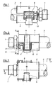
- the spout 2 is formed in the axial direction, onto which the end of the hose 3 is pushed and clamped there by the clamp generally designated 4.
- a securing tubular shell 6 covering its circumference is fastened by spot welding.
- Each of the two securing tubular half-shells 6 has at one end a holding flange 10 which engages over the collar 5.
- the radial extent of the annular collar 5 and that of the holding flanges 10 should be selected such that the clamp 4 is prevented from being pulled axially from the grommet 2 even when the clamp is open.
- the two partial shells 7 of the clamp 4 are connected to one another in an articulated manner by the hinge pin 8.
- An extension of the hinge pin 8 extends through openings in the holding flanges 10 and in this way connects not only the partial shells 7 but also the securing tubular shells 6 surrounding them, as can best be seen from FIG. 1.
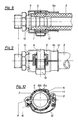
- the clamp 4 presses the hose 3 in the closed state on the spout 2, as best shown in FIG. 6.
- a safety split pin 16 can be inserted through an opening 9, the position of which, according to FIG. 5, is selected in one of the partial shells 7 in such a way that a movement of the tensioning lever 12 into the open position is impossible when the safety lock pin 16 is inserted is.
- a movement of the clamping lever 12 to open the clamp 4 is only possible after the safety pin 16 has been removed from the opening 9.
- the free end of the tensioning lever 12 spring 14 is inserted into slots 15a in one of the securing tubular half-shells 6 and 15b in the associated partial shell 7 of the clamp 4. Only after pulling this angled spring end out of the slots 15a, 15b can the clamp be opened completely and pulled off the spout in the axial direction.
- FIGS. 7 and 8 differs from that according to FIGS. 1 to 6 in the retracted section 6a of the securing tubular half-shells 6 in the region of the end of the spout 2 and beyond.
- the tapered sections 6a form a sleeve which closely surrounds the hose and in this way prevent the hose from being bent sharply around the end of the spout.
- the end of the drawn-in section 6a of the securing tubular half-shell 6 is flared in the form of an expansion 13 so that it cannot come into sharp-edged contact with the hose.
Landscapes
- Engineering & Computer Science (AREA)
- General Engineering & Computer Science (AREA)
- Mechanical Engineering (AREA)
- Quick-Acting Or Multi-Walled Pipe Joints (AREA)
- Hand Tools For Fitting Together And Separating, Or Other Hand Tools (AREA)
Applications Claiming Priority (2)
| Application Number | Priority Date | Filing Date | Title |
|---|---|---|---|
| DE3936102A DE3936102C1 (fr) | 1989-10-30 | 1989-10-30 | |
| DE3936102 | 1989-10-30 |
Publications (3)
| Publication Number | Publication Date |
|---|---|
| EP0425770A2 true EP0425770A2 (fr) | 1991-05-08 |
| EP0425770A3 EP0425770A3 (en) | 1991-08-28 |
| EP0425770B1 EP0425770B1 (fr) | 1993-02-10 |
Family
ID=6392524
Family Applications (1)
| Application Number | Title | Priority Date | Filing Date |
|---|---|---|---|
| EP90114748A Expired - Lifetime EP0425770B1 (fr) | 1989-10-30 | 1990-08-01 | Dispositif de raccordement d'un embout de tuyau souple avec un raccord |
Country Status (6)
| Country | Link |
|---|---|
| US (1) | US5074600A (fr) |
| EP (1) | EP0425770B1 (fr) |
| CA (1) | CA2023447C (fr) |
| DE (1) | DE3936102C1 (fr) |
| ES (1) | ES2040010T3 (fr) |
| ZA (1) | ZA906435B (fr) |
Cited By (2)
| Publication number | Priority date | Publication date | Assignee | Title |
|---|---|---|---|---|
| EP0523835A1 (fr) * | 1991-07-18 | 1993-01-20 | The Gates Rubber Company | Douille, dispositif d'accouplement et procédé |
| EP3359861B1 (fr) | 2015-10-06 | 2020-11-25 | Global Life Sciences Solutions USA LLC | Dispositif de serrage de raccordement |
Families Citing this family (26)
| Publication number | Priority date | Publication date | Assignee | Title |
|---|---|---|---|---|
| US5195788A (en) * | 1990-01-30 | 1993-03-23 | Hans Oetiker | Insert member for use with hose clamp arrangements |
| US5333914A (en) * | 1992-01-17 | 1994-08-02 | Toyoda Gosei Co., Ltd. | Hose device |
| US5320078A (en) * | 1992-03-11 | 1994-06-14 | Siemens Automotive L.P. | Remote mounting of a fuel pressure regulator for an engine |
| DE19637276A1 (de) * | 1996-09-13 | 1998-03-19 | Bosch Gmbh Robert | Kraftstoffördereinrichtung für Kraftfahrzeuge |
| JP3405966B2 (ja) * | 2000-02-07 | 2003-05-12 | 東尾メック株式会社 | 管継手 |
| US6796586B2 (en) | 2001-07-09 | 2004-09-28 | Twin Bay Medical, Inc. | Barb clamp |
| US6672628B2 (en) | 2002-02-20 | 2004-01-06 | Masco Corporation Of Indiana | Quick connect hose coupling |
| WO2003089797A2 (fr) | 2002-04-16 | 2003-10-30 | Werth Albert A | Bride cannelee |
| JP4531557B2 (ja) * | 2002-05-21 | 2010-08-25 | エーエスエム アメリカ インコーポレイテッド | 半導体処理ツール内チャンバ間の相互汚染の減少 |
| US7316426B2 (en) * | 2002-12-18 | 2008-01-08 | General Electric Company | Method and apparatus for coupling a conduit to a fitting |
| US7922212B2 (en) * | 2003-10-17 | 2011-04-12 | Twin Bay Medical, Inc. | Barb clamp with smooth bore |
| US7922213B2 (en) * | 2003-10-17 | 2011-04-12 | Twin Bay Medical, Inc. | Barb clamp with smooth bore |
| US20050082826A1 (en) * | 2003-10-17 | 2005-04-21 | Twin Bay Medical, Inc. | Barb clamp |
| US8256802B2 (en) * | 2003-10-17 | 2012-09-04 | Twin Bay Medical, Inc. | Barb clamp with collet interlocks |
| JP3754059B1 (ja) * | 2004-11-29 | 2006-03-08 | 井上スダレ株式会社 | 管継手 |
| US9605782B2 (en) * | 2009-04-02 | 2017-03-28 | Saint-Gobain Performance Plastics Corporation | Sanitary retainer |
| DE102009002193B4 (de) * | 2009-04-03 | 2017-12-14 | Lobbe Industrieservice Gmbh & Co Kg | Vorrichtung zum Verbinden von zwei oder mehreren Schläuchen und/oder Rohren |
| US10203058B2 (en) | 2014-04-24 | 2019-02-12 | Nordson Corporation | Reverse barb fluid connector and method of fluid connection |
| CN204387598U (zh) * | 2014-12-25 | 2015-06-10 | 佛山市南海祥旺光学电子制品有限公司 | 三脚架脚管锁紧装置 |
| US9909702B2 (en) * | 2015-06-10 | 2018-03-06 | Ford Global Technologies, Llc | Quick connect system for automotive fluid transport lines |
| WO2018185161A1 (fr) | 2017-04-05 | 2018-10-11 | Ge Healthcare Bio-Sciences Corp. | Dispositif de serrage de raccordement |
| CN108273219A (zh) * | 2017-12-13 | 2018-07-13 | 泉州旭瑞商务有限公司 | 一种带有弹性的消防水带 |
| CN109048181A (zh) * | 2018-11-02 | 2018-12-21 | 新乡市时瑞公路养护技术有限公司 | 一种滤芯端盖衬环焊接专用工装 |
| US12078270B1 (en) * | 2020-06-09 | 2024-09-03 | The United States Of America, As Represented By The Secretary Of The Navy | Dual cam lever hose clamp and methods of use thereof |
| GB2604315B (en) * | 2020-10-09 | 2025-06-18 | Scott Daniel | Improvements relating to clamps |
| CN116557663B (zh) * | 2023-05-31 | 2026-03-10 | 江苏斯必得重工机械有限公司 | 一种带有迫紧连接结构的液压软管总成 |
Family Cites Families (13)
| Publication number | Priority date | Publication date | Assignee | Title |
|---|---|---|---|---|
| BE625822A (fr) * | ||||
| US817058A (en) * | 1905-01-12 | 1906-04-03 | Edwin T Greenfield | Coupling for armored hose. |
| GB781761A (en) * | 1954-01-25 | 1957-08-28 | Kac Ltd | Improvements in or relating to pipe, hose, or like couplings |
| DE1157864B (de) * | 1958-03-18 | 1963-11-21 | Jaeger & Sohn Hochdruckhahn K | Dichtungsanordnung in Schlauchfassungen |
| BE652142A (fr) * | 1964-08-21 | 1964-12-16 | ||
| DE2104745A1 (de) * | 1971-02-02 | 1972-08-03 | Schulz H | Kmckschutzvornchtung |
| DE2230463C2 (de) * | 1972-06-22 | 1974-01-31 | Karl Ing.Grad. 4040 Neuss Weinhold | Vorrichtung zum Befestigen eines Schlauches auf einer Tülle |
| DE2553189C3 (de) * | 1975-11-27 | 1978-05-18 | Karl Ing.(Grad.) 4040 Neuss Weinhold | Vorrichtung zum lösbaren Befestigen von Schlauch- oder Rohrenden |
| DE2611174C2 (de) * | 1976-03-17 | 1978-06-15 | Karl Ing.(Grad.) 4040 Neuss Weinhold | Schlauchbefestigungsvorrichtung |
| DE2611175C3 (de) * | 1976-03-17 | 1978-09-07 | Karl Ing.(Grad.) 4040 Neuss Weinhold | Schlauchbefestigungsvorrichtung |
| US4212487A (en) * | 1978-11-17 | 1980-07-15 | Hydrasearch Co. Inc. | Hose coupling |
| DE3417924C2 (de) * | 1984-05-15 | 1986-10-02 | Karl Dipl.-Ing.(FH) 4040 Neuss Weinhold | Vorrichtung zum Verbinden eines Schlauchendes mit einem Anschlußstutzen |
| DE3721063C1 (de) * | 1987-06-26 | 1988-05-19 | Karl Dipl-Ing Weinhold | Vorrichtung zum Verbinden eines Schlauchendes mit einem Anschlussstutzen |
-
1989
- 1989-10-30 DE DE3936102A patent/DE3936102C1/de not_active Expired - Lifetime
-
1990
- 1990-08-01 ES ES199090114748T patent/ES2040010T3/es not_active Expired - Lifetime
- 1990-08-01 EP EP90114748A patent/EP0425770B1/fr not_active Expired - Lifetime
- 1990-08-14 ZA ZA906435A patent/ZA906435B/xx unknown
- 1990-08-16 CA CA002023447A patent/CA2023447C/fr not_active Expired - Fee Related
- 1990-08-21 US US07/570,435 patent/US5074600A/en not_active Expired - Lifetime
Cited By (3)
| Publication number | Priority date | Publication date | Assignee | Title |
|---|---|---|---|---|
| EP0523835A1 (fr) * | 1991-07-18 | 1993-01-20 | The Gates Rubber Company | Douille, dispositif d'accouplement et procédé |
| EP3359861B1 (fr) | 2015-10-06 | 2020-11-25 | Global Life Sciences Solutions USA LLC | Dispositif de serrage de raccordement |
| EP3359861B2 (fr) † | 2015-10-06 | 2023-12-13 | Global Life Sciences Solutions USA LLC | Dispositif de serrage de raccordement |
Also Published As
| Publication number | Publication date |
|---|---|
| ES2040010T3 (es) | 1993-10-01 |
| CA2023447A1 (fr) | 1991-05-01 |
| US5074600A (en) | 1991-12-24 |
| ZA906435B (en) | 1991-06-26 |
| DE3936102C1 (fr) | 1991-01-17 |
| CA2023447C (fr) | 2000-02-15 |
| EP0425770B1 (fr) | 1993-02-10 |
| EP0425770A3 (en) | 1991-08-28 |
Similar Documents
| Publication | Publication Date | Title |
|---|---|---|
| DE3936102C1 (fr) | ||
| DE19950619C1 (de) | Rohrkupplung mit Schnellverschluß und Rohrflansch zur Verwendung mit einer solchen Rohrkupplung | |
| DE60214479T2 (de) | Wiederverwendbare Kupplung zum Verbinden von verstärkten Schlauchenden | |
| DE1117687B (de) | Steckerarmatur fuer koaxiale Hochfrequenz-Kabel mit massivem Metallmantel | |
| DE2733526C2 (de) | Vorrichtung zum lösbaren Verbinden der Kolbenstange und des Kolbens einer Injektionsspritze | |
| EP0137961A1 (fr) | Dispositif extracteur pour une brique pour lavage au gaz | |
| DE69430403T2 (de) | Selbstspannende Klemmschellenstruktur | |
| DE4015404A1 (de) | Rohrschelle | |
| EP0319746A1 (fr) | Dispositif d'accouplement de deux conduites, en particulier pour des conduites de carburant | |
| DE3532505C1 (de) | Anschlusskupplung | |
| DE3417924C2 (de) | Vorrichtung zum Verbinden eines Schlauchendes mit einem Anschlußstutzen | |
| DE3911688A1 (de) | Kabelende-abschliessvorrichtung | |
| EP1354162B1 (fr) | Raccord, equipe d'une bague de glissement, pour le raccordement de deux tuyaux d'incendie | |
| DE102008063582A1 (de) | Rohrschelle | |
| EP0288993B2 (fr) | Dispositif pour assemblage des extrémités coaxiales de deux tuyaux sans manchons | |
| DE3739745C1 (en) | Connecting and joining sleeve for flexible tubes | |
| DE9103511U1 (de) | Vorrichtung zum Verbinden von Rohren | |
| DE7933147U1 (de) | Verbindungsvorrichtung fuer schmiegsame oder halbschmiegsame rohre | |
| DE3921443C2 (fr) | ||
| DE4329650C2 (de) | Schlauchfassung | |
| DE2611175A1 (de) | Chlauchbefestigungsvorrichtung | |
| DE3721063C1 (de) | Vorrichtung zum Verbinden eines Schlauchendes mit einem Anschlussstutzen | |
| EP1065428B1 (fr) | Manchon de soudage | |
| DE4343877C1 (de) | Rohrschelle | |
| DE3436951C2 (de) | Schlauchbefestigung mit einem gehäuseintegrierten außen zylindrischen Schlauchanschlußstutzen und einer Federklemme |
Legal Events
| Date | Code | Title | Description |
|---|---|---|---|
| PUAI | Public reference made under article 153(3) epc to a published international application that has entered the european phase |
Free format text: ORIGINAL CODE: 0009012 |
|
| AK | Designated contracting states |
Kind code of ref document: A2 Designated state(s): ES FR GB IT SE |
|
| PUAL | Search report despatched |
Free format text: ORIGINAL CODE: 0009013 |
|
| AK | Designated contracting states |
Kind code of ref document: A3 Designated state(s): ES FR GB IT SE |
|
| 17P | Request for examination filed |
Effective date: 19910910 |
|
| 17Q | First examination report despatched |
Effective date: 19920326 |
|
| GRAA | (expected) grant |
Free format text: ORIGINAL CODE: 0009210 |
|
| AK | Designated contracting states |
Kind code of ref document: B1 Designated state(s): ES FR GB IT SE |
|
| ET | Fr: translation filed | ||
| GBT | Gb: translation of ep patent filed (gb section 77(6)(a)/1977) |
Effective date: 19930222 |
|
| ITF | It: translation for a ep patent filed | ||
| REG | Reference to a national code |
Ref country code: ES Ref legal event code: FG2A Ref document number: 2040010 Country of ref document: ES Kind code of ref document: T3 |
|
| PLBE | No opposition filed within time limit |
Free format text: ORIGINAL CODE: 0009261 |
|
| STAA | Information on the status of an ep patent application or granted ep patent |
Free format text: STATUS: NO OPPOSITION FILED WITHIN TIME LIMIT |
|
| 26N | No opposition filed | ||
| EAL | Se: european patent in force in sweden |
Ref document number: 90114748.8 |
|
| REG | Reference to a national code |
Ref country code: GB Ref legal event code: IF02 |
|
| PGFP | Annual fee paid to national office [announced via postgrant information from national office to epo] |
Ref country code: SE Payment date: 20040827 Year of fee payment: 15 Ref country code: ES Payment date: 20040827 Year of fee payment: 15 |
|
| PG25 | Lapsed in a contracting state [announced via postgrant information from national office to epo] |
Ref country code: IT Free format text: LAPSE BECAUSE OF NON-PAYMENT OF DUE FEES;WARNING: LAPSES OF ITALIAN PATENTS WITH EFFECTIVE DATE BEFORE 2007 MAY HAVE OCCURRED AT ANY TIME BEFORE 2007. THE CORRECT EFFECTIVE DATE MAY BE DIFFERENT FROM THE ONE RECORDED. Effective date: 20050801 |
|
| PG25 | Lapsed in a contracting state [announced via postgrant information from national office to epo] |
Ref country code: ES Free format text: LAPSE BECAUSE OF NON-PAYMENT OF DUE FEES Effective date: 20050802 Ref country code: SE Free format text: LAPSE BECAUSE OF NON-PAYMENT OF DUE FEES Effective date: 20050802 |
|
| EUG | Se: european patent has lapsed | ||
| PGFP | Annual fee paid to national office [announced via postgrant information from national office to epo] |
Ref country code: FR Payment date: 20060829 Year of fee payment: 17 Ref country code: GB Payment date: 20060829 Year of fee payment: 17 |
|
| REG | Reference to a national code |
Ref country code: ES Ref legal event code: FD2A Effective date: 20050802 |
|
| GBPC | Gb: european patent ceased through non-payment of renewal fee |
Effective date: 20070801 |
|
| REG | Reference to a national code |
Ref country code: FR Ref legal event code: ST Effective date: 20080430 |
|
| PG25 | Lapsed in a contracting state [announced via postgrant information from national office to epo] |
Ref country code: FR Free format text: LAPSE BECAUSE OF NON-PAYMENT OF DUE FEES Effective date: 20070831 |
|
| PG25 | Lapsed in a contracting state [announced via postgrant information from national office to epo] |
Ref country code: GB Free format text: LAPSE BECAUSE OF NON-PAYMENT OF DUE FEES Effective date: 20070801 |