EP0425872A2 - Verfahren und Vorrichtung zur Herstellung einer Scheibe zum Polieren - Google Patents
Verfahren und Vorrichtung zur Herstellung einer Scheibe zum Polieren Download PDFInfo
- Publication number
- EP0425872A2 EP0425872A2 EP90119664A EP90119664A EP0425872A2 EP 0425872 A2 EP0425872 A2 EP 0425872A2 EP 90119664 A EP90119664 A EP 90119664A EP 90119664 A EP90119664 A EP 90119664A EP 0425872 A2 EP0425872 A2 EP 0425872A2
- Authority
- EP
- European Patent Office
- Prior art keywords
- polishing
- mold part
- casting compound
- grinding
- support plate
- Prior art date
- Legal status (The legal status is an assumption and is not a legal conclusion. Google has not performed a legal analysis and makes no representation as to the accuracy of the status listed.)
- Granted
Links
Images

Classifications
-
- B—PERFORMING OPERATIONS; TRANSPORTING
- B24—GRINDING; POLISHING
- B24D—TOOLS FOR GRINDING, BUFFING OR SHARPENING
- B24D13/00—Wheels having flexibly-acting working parts, e.g. buffing wheels; Mountings therefor
- B24D13/02—Wheels having flexibly-acting working parts, e.g. buffing wheels; Mountings therefor acting by their periphery
- B24D13/12—Wheels having flexibly-acting working parts, e.g. buffing wheels; Mountings therefor acting by their periphery comprising assemblies of felted or spongy material, e.g. felt, steel wool, foamed latex
-
- B—PERFORMING OPERATIONS; TRANSPORTING
- B24—GRINDING; POLISHING
- B24D—TOOLS FOR GRINDING, BUFFING OR SHARPENING
- B24D3/00—Physical features of abrasive bodies, or sheets, e.g. abrasive surfaces of special nature; Abrasive bodies or sheets characterised by their constituents
- B24D3/02—Physical features of abrasive bodies, or sheets, e.g. abrasive surfaces of special nature; Abrasive bodies or sheets characterised by their constituents the constituent being used as bonding agent
- B24D3/20—Physical features of abrasive bodies, or sheets, e.g. abrasive surfaces of special nature; Abrasive bodies or sheets characterised by their constituents the constituent being used as bonding agent and being essentially organic
- B24D3/22—Rubbers synthetic or natural
- B24D3/26—Rubbers synthetic or natural for porous or cellular structure
Definitions
- the invention relates to a method for producing a disk for polishing or grinding image slurries according to the preamble of claim 1.
- Polishing or grinding wheels for processing glass, metal or other materials are known in various embodiments (DE-U-71 16 473, DE-A-26 32 012, DE-A-28 15 468, DE-A-34 16 186).
- the actual polishing layer consists of a foamed special plastic.
- This layer which is a few mm thick, is now glued by hand to a rubber support plate, then profiled, ie provided with profile grooves, so that a honeycomb pattern or segmentation is produced similar to the disk according to DE-U-71 16 473.
- This profiling gives the disc flexibility; and the grooves, arranged in a star shape and radially, serve to distribute the liquid grinding suspension.
- the method according to the invention according to the characterizing part of claim 1 has the following advantages: - Homogeneous and permanent connection of the polishing or grinding surface and the backing plate in one operation; - Form-side formation of the entire segmentation (star-shaped and radial grooves); all sharp edges and corners are rounded, therefore no notch effect; - The almost uniform wall thickness gives the polishing or grinding wheel the necessary flexibility; the significantly reduced material cross-sections reduce the internal heat generated by flexing work and, on the other hand, dissipate frictional heat better; - By using a hard polyurethane quality with a high modulus of elasticity, the mechanical-technological property level is significantly improved compared to a soft rubber quality.
- the casting compound is first formed in a two-component reaction (process stage A) by reacting 1,5-naphthylene di-isocyanate (Desmodur 15; Bayer) with a polyester polyol (MG 2000).
- the reaction temperature is 125 to 135 ° C, especially 130 ° C. This is followed by rapid cooling to 110 to 120 ° C (process stage B).
- process stage C After adding 1,4-butanediol as crosslinker (chain extender) (process stage C), the casting compound is introduced into the feed opening of the rotary device after 45 seconds at the latest (process stage D).
- the casting compound is introduced at a rotational speed of 320 to 350 revolutions / minute in two stages, batch I being about 2/3 of the total casting compound.
- the pot life of the total casting compound is a maximum of 15 minutes, in particular 7 to 10 minutes.
- the pot life is the period from the start of adding the crosslinker (liquid phase) to Crosslinking end of the casting compound (solid phase) understood. It is important here that within this pot life the casting compound forming the support plate completely fills the corresponding recesses of the rotary device with simultaneous air displacement. It is also important that the impregnation effect at the speed of rotation according to the invention is kept low compared to the foam plastic forming the polishing or abrasive coating with a simultaneously homogeneous connection.
- the two-batch process described above is a particularly advantageous procedural measure from these two points of view.
- the rotary device (1) consists essentially of a lower mold part (2), upper mold part (3), a loading opening (4) and a conical double chamber system (5, 6).
- the segments forming the polishing and grinding covering made of foamed polyether urethane impregnated with inorganic substances are inserted.
- the casting compound is introduced into the rotating device via the loading opening (4) which opens into the double-chamber system (5, 6). Due to the centrifugal forces, the casting compound is initially in the cone area (9, 10) of the chambers (5, 6). Finally, the casting compound reaches the recesses (12, 13) of the upper mold part (3) from the widest point (11) of this chamber system.
- the temperatures of the lower mold part (2) and the upper mold part (3) are at least 100 ° C, in particular 110 ⁇ 5 ° C.
- the volume ratio of the chamber (5) and the chamber (6) is 1: 2 to 1: 4.
- Hole pins (14) form the bores (18) - FIGS. 3, 4 - within the support plate.
- the disc (15) for polishing or grinding screens consists of the following parts: Support plate (16) with bores (17, 18, 19) and a cylindrical step (20) arranged on the rear; Polishing or grinding covering (21) which has segments (22, 23, 24); star-shaped grooves (25, 26, 27); radially extending grooves (28, 29); Indentation (30) in the center of the pane.
- the support plate (16) made of solid polyurethane elastomer, in particular based on a polyester polyurethane, has a minimum hardness in Shore A of 90 ° and an elastic modulus of 50 to 60 MPa. Its thickness is approximately 4 mm or 8 mm (in the area of the segments 22, 23, 24).
- the cylindrical step (20) has a depth of 8 to 12 mm and gives the disc a particularly high degree of flexibility.
- the segments (22, 23, 24) of the polishing or grinding surface (21) are structured in three rows, in such a way that every second star-shaped groove (25, 26) is arranged continuously up to the recess (30) in the center of the wheel, while the star-shaped grooves (27) between them only extend to the radial groove (28).
- the thickness of the segments (22, 23, 24) of the polishing or grinding covering (21) is 4 to 6 mm.
Landscapes
- Engineering & Computer Science (AREA)
- Mechanical Engineering (AREA)
- Polishing Bodies And Polishing Tools (AREA)
- Grinding Of Cylindrical And Plane Surfaces (AREA)
- Moulding By Coating Moulds (AREA)
- Finish Polishing, Edge Sharpening, And Grinding By Specific Grinding Devices (AREA)
Abstract
- einem Stützteller (16) aus elastomerem Werkstoff und
- einem segmentierten Polier- bzw. Schleifbelag (21) aus Kunststoff, insbesondere aus geschäumtem Kunststoff,
wobei die einzelnen Segmente (22, 23, 24) durch sternförmig und radial verlaufende Nuten (25, 26, 27; 28, 29) voneinander getrennt sind.
- in die Nester des Formunterteils der Rotationsvorrichtung werden die Segmente (22, 23, 24) eingesetzt;
- nach Schließen der Rotationsvorrichtung werden Formunterteil und Formoberteil aufgeheizt;
- die Vorrichtung wird auf eine Mindestrotationsgeschwindigkeit von 300 Umdrehungen/Minute gebracht;
- die in einer Mischvorrichtung hergestellte Gießmasse, insbesondere auf der Basis eines Polyurethan-Elastomers, wird mit einem Vernetzer versetzt;
- nach Zugabe des Vernetzers wird die Gießmasse möglichst schnell in die Beschickungsöffnung der Rotationsvorrichtung gebracht, wovon aus sie sich unter dem Einfluß der Zentrifugalkraft bei gleichzeitiger Luftverdrängung und Vernetzung in die den Stützteller bildenden Aussparungen innerhalb des Formoberteils ergießt.
Description
- Die Erfindung betrifft ein Verfahren zur Herstellung einer Scheibe zum Polieren bzw. Schleifen von Bildschlrmen gemäß Oberbegriff des Anspruchs 1.
- Polier- bzw. Schleifscheiben für die Bearbeitung von Glas, Metall oder anderen Werkstoffen sind in verschiedenen Ausführungsformen bekannt (DE-U-71 16 473, DE-A-26 32 012, DE-A-28 15 468, DE-A-34 16 186).
- Die heutigen superflachen Bildschirme haben eine asphärisch gekrümmte Oberfläche. Diese einwandfrei zu polieren bzw. zu schleifen, erfordert eine besonders konstruierte Polier- bzw. Schleifscheibe. Zur Drehrichtung der Scheibe kommt eine oszillierende Bewegung des Scheibenmittelpunktes über die Bildschirmfläche hinzu.
- Die eigentliche Polierschicht besteht dabei aus einem geschäumtem Spezialkunststoff. Diese wenige mm-starke Schicht wird heute in aufwendiger Handarbeit auf eine Gummiträgerplatte geklebt, anschließend profiliert, d.h. mit Profilnuten versehen, so daß ähnlich der Scheibe nach der DE-U-71 16 473 ein Wabenmuster bzw. eine Segmentierung entsteht. Diese Profilierung verleiht der Scheibe Flexibilität; und die Nuten, sternförmig und radial angeordnet, dienen zur Verteilung der flüssigen Schleifsuspension.
- Mit diesem Scheibenaufbau bzw. mit dem hier geschilderten Herstellungsverfahren sind jedoch folgende Nachteile verbunden:
- hoher manueller Aufwand beim Verkleben und Schneiden;
- Umweltbelastung durch Einsatz großer Mengen Cyanacrylatkleber;
- mangelnde Verklebung führt zu vorzeitigem Ausfall;
- durch Nachschneiden der Gummi-Trägerplatte besteht die Gefahr von Rißbildungen durch Kerbwirkung; solche Risse führen aufgrund der enormen Belastung zu vorzeitiger Zerstörung und damit zu Produktionsstillstand;
- ungünstige Ableitung der Friktionswärme durch notwendige, starke Querschnitte der Gummi-Trägerplatte;
- die durchschnittliche Lebensdauer der bisherigen Polierscheibe beträgt je nach Schirmgröße lediglich 5000 bis 8000 Zyklen (= Bildschirme). - Das erfindungsgemäße Verfahren gemäß Kennzeichen des Anspruchs 1 bringt dagegen folgende Vorteile:
- homogene und dauerhafte Verbindung des Polier- bzw. Schleifbelages und des Stütztellers in einem Arbeitsgang;
- formseitige Ausbildung der gesamten Segmentierung (sternförmig und radial verlaufende Nuten); alle scharfen Kanten und Ecken sind verrundet, daher keine Kerbwirkung;
- durch nahezu gleichmäßigen Wanddickenverlauf erhält die Polier- bzw. Schleifscheibe die nötige Flexibilität; die erheblich reduzierten Materialquerschnitte vermindern durch Walkarbeit entstehende innere Wärmeentwicklung und führen andererseits Reibungswärme besser ab;
- durch den Einsatz einer harten Polyurethan-Qualität mit hohem E-Modul wird im Vergleich zu einer weichen Gummi-Qualität das mechanisch-technologische Eigenschaftsniveau wesentlich verbessert. - Alle Punkte zusammengenommen verleihen der Polier- bzw. Schleifscheibe eine wesentlich höhere Lebensdauer, Betriebssicherheit und Wirtschaftlichkeit.
- Die Erfindung wird nun anhand von Ausführungsbeispielen unter Bezugnahme auf schematische Zeichnungen näher erläutert. Es zeigen:
- Fig. 1 den Verfahrensablauf in Form eines Blockschemas;
- Fig. 2 Rotationsvorrichtung;
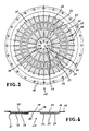
- Fig. 3 Polier- bzw. Schleifscheibe (Frontansicht);
- Fig. 4 Polier- bzw. Schleifscheibe (Schnittansicht)
- Nach Fig. 1 wird zunächst im Rahmen einer Zwei-Komponenten-Reaktion (Verfahrensstufe A) durch Umsetzung von 1,5-Naphthylen-di-isocyanat (Desmodur 15; Fa. Bayer) mit einem Polyesterpolyol (MG 2000) die Gießmasse gebildet. Die Reaktionstemperatur beträgt 125 bis 135°C, insbesondere 130°C. Anschließend erfolgt eine rasche Abkühlung auf 110 bis 120°C (Verfahrensstufe B). Nach Zugabe von Butandiol-1,4 als Vernetzer (Kettenverlängerer) (Verfahrensstufe C) wird die Gießmasse spätestens nach 45 sec in die Beschickungsöffnung der Rotationsvorrichtung gebracht (Verfahrensstufe D). Das Einbringen der Gießmasse bei einer Rotationsgeschwindigkeit von 320 bis 350 Umdrehungen/Minute erfolgt dabei in zwei Stufen, wobei die Charge I etwa 2/3 der Gesamtgießmasse ist. Die Zugabe der Charge II wird 3 bis 5 Minuten nach Eingeben der Charge I vorgenommen. Die Topfzeit der Gesamtgießmasse beträgt maximal 15 Minuten, insbesondere 7 bis 10 Minuten. Unter der Topfzeit wird hier der Zeitraum von Beginn der Zugabe des Vernetzers (flüssige Phase) bis zum Vernetzungsende der Gießmasse (feste Phase) verstanden. Wichtig dabei ist, daß innerhalb dieser Topfzeit die den Stützteller bildende Gießmasse bei gleichzeitiger Luftverdrängung vollständig die entsprechenden Aussparungen der Rotationsvorrichtung ausfüllt. Von Bedeutung ist ferner, daß der Tränkungseffekt bei der erfindungsgemäßen Rotationsgeschwindigkeit gegenüber dem den Polier- bzw. Schleifbelag bildenden Schaumkunststoff bei gleichzeitig homogener Verbindung niedrig gehalten wird. Das oben geschilderte Zwei-Chargen-Verfahren ist unter diesen beiden Gesichtspunkten eine besonders vorteilhafte verfahrenstechnische Maßnahme.
- Nach Fig. 2 besteht die Rotationsvorrichtung (1) im wesentlichen aus einem Formunterteil (2), Formoberteil (3), einer Beschickungsöffnung (4) sowie einem konischen Doppelkammersystem (5, 6). In die Nester (7, 8) des Formunterteils (3) werden die den Polier- und Schleifbelag bildenden Segmente aus geschäumtem, mit anorganischen Substanzen getränktem Polyetherurethan eingesetzt. Das Einbringen der Gießmasse in die Rotationsvorrichtung erfolgt über die Beschickungsöffnung (4), die in das Doppelkammersystem (5, 6) mündet. Aufgrund der Zentrifugalkräfte hält sich die Gießmasse zunächst im Konus-Bereich (9, 10) der Kammern (5, 6) auf. Schließlich gelangt die Gießmasse von der breitesten Stelle (11) dieses Kammersystems aus in die Aussparungen (12, 13) des Formoberteils (3). Die Temperaturen des Formunterteils (2) und des Formoberteils (3) betragen mindestens 100°C, insbesondere 110 ± 5°C. Bezüglich der Gießmassenverteilung ist es zweckmäßig, wenn das Volumenverhältnis der Kammer (5) und der Kammer (6) 1 : 2 bis 1 : 4 beträgt. Lochstifte (14) bilden die Bohrungen (18) - Fig. 3, 4 - innerhalb des Stütztellers.
- Nach den Fig. 3 und 4 besteht die Scheibe (15) zum Polieren bzw. Schleifen von Bildschirmen aus folgenden Teilen:
Stützteller (16) mit Bohrungen (17, 18, 19) und einer rückseitig angeordneten zylindrischen Abstufung (20);
Polier- bzw. Schleifbelag (21), der Segmente (22, 23, 24) aufweist;
sternförmig verlaufende Nuten (25, 26, 27);
radial verlaufende Nuten (28, 29);
Vertiefung (30) im Scheibenmittelpunkt. - Der Stützteller (16) aus massivem Polyurethan-Elastomer, insbesondere auf der Basis eines Polyester-Polyurethans, weist eine Mindesthärte in Shore A von 90° und einen Elastizitätsmodul von 50 bis 60 MPa auf. Seine Stärke beträgt etwa 4 mm bzw. 8 mm (im Bereich der Segmente 22, 23, 24). Die zylindrische Abstufung (20) weist eine Tiefe von 8 bis 12 mm auf und verleiht der Scheibe eine besonders hohe Flexibilität.
- Die Segmente (22, 23, 24) des Polier- bzw. Schleifbelages (21) sind dreireihig strukturiert, und zwar derart, daß jede zweite sternförmig verlaufende Nut (25, 26) bis zur Vertiefung (30) im Scheibenmittelpunkt durchgehend angeordnet ist, während die dazwischen liegenden sternförmig verlaufenden Nuten (27) nur bis zur Radialnut (28) reichen. Die Stärke der Segmente (22, 23, 24) des Polier- bzw. Schleifbelages (21) beträgt 4 bis 6 mm.
Claims (25)
- einem Stützteller (16) aus elastomerem Werkstoff und
- einem segmentierten Polier- bzw. Schleifbelag (21) aus Kunststoff, insbesondere aus geschäumtem Kunststoff, wobei die einzelnen Segmente (22, 23, 24) durch sternförmig und radial verlaufende Nuten (25, 26, 27; 28, 29) voneinander getrennt sind,
gekennzeichnet durch folgende Verfahrensschritte:
- in die Nester (7, 8) des Formunterteils (2) der Rotationsvorrichtung (1) werden die Segmente (22, 23, 24) eingesetzt;
- nach Schließen der Rotationsvorrichtung (1) werden Formunterteil (2) und Formoberteil (3) aufgeheizt;
- die Vorrichtung (1) wird auf eine Mindestrotationsgeschwindigkeit von 300 Umdrehungen/Minute gebracht;
- die in einer Mischvorrichtung hergestellte Gießmasse, insbesondere auf der Basis eines Polyurethan-Elastomers, wird mit einem Vernetzer versetzt;
- nach Zugabe des Vernetzers wird die Gießmasse möglichst schnell in die Beschickungsöffnung (4) der Rotationsvorrichtung (1) gebracht, wovon aus sie sich unter dem Einfluß der Zentrifugalkraft bei gleichzeitiger Luftverdrängung und Vernetzung in die den Stützteller (16) bildenden Aussparungen (12, 13) innerhalb des Formoberteils (3) ergießt.
Minute, beträgt.
Applications Claiming Priority (2)
| Application Number | Priority Date | Filing Date | Title |
|---|---|---|---|
| DE3935285 | 1989-10-24 | ||
| DE3935285 | 1989-10-24 |
Publications (3)
| Publication Number | Publication Date |
|---|---|
| EP0425872A2 true EP0425872A2 (de) | 1991-05-08 |
| EP0425872A3 EP0425872A3 (en) | 1992-03-11 |
| EP0425872B1 EP0425872B1 (de) | 1995-01-04 |
Family
ID=6392024
Family Applications (1)
| Application Number | Title | Priority Date | Filing Date |
|---|---|---|---|
| EP90119664A Expired - Lifetime EP0425872B1 (de) | 1989-10-24 | 1990-10-13 | Verfahren und Vorrichtung zur Herstellung einer Scheibe zum Polieren |
Country Status (3)
| Country | Link |
|---|---|
| EP (1) | EP0425872B1 (de) |
| AT (1) | ATE116589T1 (de) |
| DE (1) | DE59008192D1 (de) |
Family Cites Families (6)
| Publication number | Priority date | Publication date | Assignee | Title |
|---|---|---|---|---|
| GB456985A (en) * | 1935-05-18 | 1936-11-18 | Carborundum Co | Improvements in abrasive articles |
| US3252775A (en) * | 1962-04-10 | 1966-05-24 | Tocci-Guilbert Berne | Foamed polyurethane abrasive wheels |
| US3391423A (en) * | 1964-08-07 | 1968-07-09 | Osborn Mfg Co | Apparatus for making abrasive articles |
| DE3219567A1 (de) * | 1982-05-25 | 1983-12-01 | SEA Schleifmittel Entwicklung Anwendung GmbH, 7530 Pforzheim | Elastischer schleifkoerper und verfahren zu seiner herstellung |
| FR2540025B1 (fr) * | 1983-01-28 | 1991-05-10 | Precidia | Outil rotatif comportant un corps de revolution pourvu d'elements actifs pour usiner des materiaux tels que du granit, du marbre ou un produit refractaire |
| DE3442230A1 (de) * | 1984-11-19 | 1986-05-28 | Tyrolit-Schleifmittelwerke Swarovski KG, Schwaz, Tirol | Verfahren zur herstellung einer schleifscheibe |
-
1990
- 1990-10-13 AT AT90119664T patent/ATE116589T1/de not_active IP Right Cessation
- 1990-10-13 EP EP90119664A patent/EP0425872B1/de not_active Expired - Lifetime
- 1990-10-13 DE DE59008192T patent/DE59008192D1/de not_active Expired - Fee Related
Also Published As
| Publication number | Publication date |
|---|---|
| EP0425872A3 (en) | 1992-03-11 |
| EP0425872B1 (de) | 1995-01-04 |
| ATE116589T1 (de) | 1995-01-15 |
| DE59008192D1 (de) | 1995-02-16 |
Similar Documents
| Publication | Publication Date | Title |
|---|---|---|
| DE3714176C2 (de) | Form zum Anformen einer Dichtung | |
| DE69412050T2 (de) | Exzenterschleifmaschine mit Bremskörper | |
| EP0095055B1 (de) | Verfahren zur Herstellung eines Schleifkörpers | |
| DE2023121A1 (de) | Strukturierte Verkleidungstafeln und Verfahren zur Herstellung strukturierter Flaechen | |
| DE69715321T2 (de) | Verfahren und Vorrichtung zum Abrichten eines Poliertuches | |
| DE19803495B4 (de) | Spiralstrom-Trommelbearbeitungsmaschine und Verfahren zur Herstellung einer Ausweichschicht dafür | |
| DE3416186A1 (de) | Schleifscheibe | |
| DE69514996T2 (de) | Mahlverfahren und Auskleidung für Mahltrommel | |
| DE3440961C1 (de) | Verfahren zum Herstellen von gehaerteten Laufscheiben fuer Axialwaelzlager | |
| DE3537331C2 (de) | ||
| EP0425872B1 (de) | Verfahren und Vorrichtung zur Herstellung einer Scheibe zum Polieren | |
| DE1752612A1 (de) | Schleifkoerper | |
| DE29910931U1 (de) | Werkzeugträger | |
| DE4032540A1 (de) | Verfahren und vorrichtung zur herstellung einer scheibe zum polieren bzw. schleifen von bildschirmen | |
| DE19651626A1 (de) | Honwerkzeug und Verfahren zu dessen Herstellung | |
| DE2322602A1 (de) | Laepp-kissen | |
| DE1812250B2 (de) | Verfahren zur herstellung von kleinen elastomeren polyurethan teilchen | |
| DE2301312C2 (de) | Verfahren zur Herstellung eines profilierten Honwerkzeugs | |
| DE10015418C2 (de) | Schleifwerkzeug und Verfahren zu dessen Herstellung | |
| DE1502648A1 (de) | Verstaerkte,flexible Schleifscheibe | |
| DE4019028A1 (de) | Stuetzscheibe fuer eine stuetzscheibenlagerung fuer oe-spinnrotoren und verfahren zu ihrer herstellung | |
| DE2230720A1 (de) | Schleifscheibe mit diamant- oder bornitridschleifkoernern | |
| DE4108699C2 (de) | Flaschendrehteller | |
| DE2521486A1 (de) | Verfahren zum herstellen von formkoerpern aus zaehelastischen, granulatartig zerkleinerten gummiflocken, sowie vorrichtung zur durchfuehrung des verfahrens | |
| DE3800257C1 (en) | Press for plastic compositions |
Legal Events
| Date | Code | Title | Description |
|---|---|---|---|
| PUAI | Public reference made under article 153(3) epc to a published international application that has entered the european phase |
Free format text: ORIGINAL CODE: 0009012 |
|
| 17P | Request for examination filed |
Effective date: 19901221 |
|
| AK | Designated contracting states |
Kind code of ref document: A2 Designated state(s): AT BE CH DE ES FR GB IT LI NL SE |
|
| GBC | Gb: translation of claims filed (gb section 78(7)/1977) | ||
| PUAL | Search report despatched |
Free format text: ORIGINAL CODE: 0009013 |
|
| AK | Designated contracting states |
Kind code of ref document: A3 Designated state(s): AT BE CH DE ES FR GB IT LI NL SE |
|
| 17Q | First examination report despatched |
Effective date: 19930111 |
|
| GRAA | (expected) grant |
Free format text: ORIGINAL CODE: 0009210 |
|
| AK | Designated contracting states |
Kind code of ref document: B1 Designated state(s): AT BE CH DE ES FR GB IT LI NL SE |
|
| PG25 | Lapsed in a contracting state [announced via postgrant information from national office to epo] |
Ref country code: IT Free format text: LAPSE BECAUSE OF FAILURE TO SUBMIT A TRANSLATION OF THE DESCRIPTION OR TO PAY THE FEE WITHIN THE PRE;WARNING: LAPSES OF ITALIAN PATENTS WITH EFFECTIVE DATE BEFORE 2007 MAY HAVE OCCURRED AT ANY TIME BEFORE 2007. THE CORRECT EFFECTIVE DATE MAY BE DIFFERENT FROM THE ONE RECORDED.SCRIBED TIME-LIMIT Effective date: 19950104 Ref country code: FR Effective date: 19950104 Ref country code: BE Effective date: 19950104 Ref country code: NL Effective date: 19950104 Ref country code: ES Free format text: THE PATENT HAS BEEN ANNULLED BY A DECISION OF A NATIONAL AUTHORITY Effective date: 19950104 |
|
| REF | Corresponds to: |
Ref document number: 116589 Country of ref document: AT Date of ref document: 19950115 Kind code of ref document: T |
|
| REF | Corresponds to: |
Ref document number: 59008192 Country of ref document: DE Date of ref document: 19950216 |
|
| PG25 | Lapsed in a contracting state [announced via postgrant information from national office to epo] |
Ref country code: SE Effective date: 19950404 |
|
| GBT | Gb: translation of ep patent filed (gb section 77(6)(a)/1977) |
Effective date: 19950305 |
|
| EN | Fr: translation not filed | ||
| NLV1 | Nl: lapsed or annulled due to failure to fulfill the requirements of art. 29p and 29m of the patents act | ||
| PG25 | Lapsed in a contracting state [announced via postgrant information from national office to epo] |
Ref country code: GB Effective date: 19951013 Ref country code: AT Effective date: 19951013 |
|
| PG25 | Lapsed in a contracting state [announced via postgrant information from national office to epo] |
Ref country code: CH Effective date: 19951031 Ref country code: LI Effective date: 19951031 |
|
| PLBE | No opposition filed within time limit |
Free format text: ORIGINAL CODE: 0009261 |
|
| STAA | Information on the status of an ep patent application or granted ep patent |
Free format text: STATUS: NO OPPOSITION FILED WITHIN TIME LIMIT |
|
| 26N | No opposition filed | ||
| GBPC | Gb: european patent ceased through non-payment of renewal fee |
Effective date: 19951013 |
|
| REG | Reference to a national code |
Ref country code: CH Ref legal event code: PL |
|
| PG25 | Lapsed in a contracting state [announced via postgrant information from national office to epo] |
Ref country code: DE Effective date: 19960702 |