EP0425876A2 - Accumulateur hydropneumatique à piston - Google Patents
Accumulateur hydropneumatique à piston Download PDFInfo
- Publication number
- EP0425876A2 EP0425876A2 EP90119695A EP90119695A EP0425876A2 EP 0425876 A2 EP0425876 A2 EP 0425876A2 EP 90119695 A EP90119695 A EP 90119695A EP 90119695 A EP90119695 A EP 90119695A EP 0425876 A2 EP0425876 A2 EP 0425876A2
- Authority
- EP
- European Patent Office
- Prior art keywords
- piston
- separating piston
- separating
- accumulator according
- pressure
- Prior art date
- Legal status (The legal status is an assumption and is not a legal conclusion. Google has not performed a legal analysis and makes no representation as to the accuracy of the status listed.)
- Withdrawn
Links
Images



Classifications
-
- F—MECHANICAL ENGINEERING; LIGHTING; HEATING; WEAPONS; BLASTING
- F16—ENGINEERING ELEMENTS AND UNITS; GENERAL MEASURES FOR PRODUCING AND MAINTAINING EFFECTIVE FUNCTIONING OF MACHINES OR INSTALLATIONS; THERMAL INSULATION IN GENERAL
- F16F—SPRINGS; SHOCK-ABSORBERS; MEANS FOR DAMPING VIBRATION
- F16F9/00—Springs, vibration-dampers, shock-absorbers, or similarly-constructed movement-dampers using a fluid or the equivalent as damping medium
- F16F9/06—Springs, vibration-dampers, shock-absorbers, or similarly-constructed movement-dampers using a fluid or the equivalent as damping medium using both gas and liquid
- F16F9/064—Units characterised by the location or shape of the expansion chamber
- F16F9/065—Expansion chamber provided on the upper or lower end of a damper, separately there from or laterally on the damper
-
- B—PERFORMING OPERATIONS; TRANSPORTING
- B60—VEHICLES IN GENERAL
- B60G—VEHICLE SUSPENSION ARRANGEMENTS
- B60G11/00—Resilient suspensions characterised by arrangement, location or kind of springs
- B60G11/26—Resilient suspensions characterised by arrangement, location or kind of springs having fluid springs only, e.g. hydropneumatic springs
-
- B—PERFORMING OPERATIONS; TRANSPORTING
- B60—VEHICLES IN GENERAL
- B60G—VEHICLE SUSPENSION ARRANGEMENTS
- B60G17/00—Resilient suspensions having means for adjusting the spring or vibration-damper characteristics, for regulating the distance between a supporting surface and a sprung part of vehicle or for locking suspension during use to meet varying vehicular or surface conditions, e.g. due to speed or load
- B60G17/015—Resilient suspensions having means for adjusting the spring or vibration-damper characteristics, for regulating the distance between a supporting surface and a sprung part of vehicle or for locking suspension during use to meet varying vehicular or surface conditions, e.g. due to speed or load the regulating means comprising electric or electronic elements
- B60G17/0152—Resilient suspensions having means for adjusting the spring or vibration-damper characteristics, for regulating the distance between a supporting surface and a sprung part of vehicle or for locking suspension during use to meet varying vehicular or surface conditions, e.g. due to speed or load the regulating means comprising electric or electronic elements characterised by the action on a particular type of suspension unit
-
- B—PERFORMING OPERATIONS; TRANSPORTING
- B60—VEHICLES IN GENERAL
- B60G—VEHICLE SUSPENSION ARRANGEMENTS
- B60G17/00—Resilient suspensions having means for adjusting the spring or vibration-damper characteristics, for regulating the distance between a supporting surface and a sprung part of vehicle or for locking suspension during use to meet varying vehicular or surface conditions, e.g. due to speed or load
- B60G17/02—Spring characteristics, e.g. mechanical springs and mechanical adjusting means
- B60G17/04—Spring characteristics, e.g. mechanical springs and mechanical adjusting means fluid spring characteristics
- B60G17/0416—Spring characteristics, e.g. mechanical springs and mechanical adjusting means fluid spring characteristics regulated by varying the resiliency of hydropneumatic suspensions
-
- B—PERFORMING OPERATIONS; TRANSPORTING
- B60—VEHICLES IN GENERAL
- B60G—VEHICLE SUSPENSION ARRANGEMENTS
- B60G17/00—Resilient suspensions having means for adjusting the spring or vibration-damper characteristics, for regulating the distance between a supporting surface and a sprung part of vehicle or for locking suspension during use to meet varying vehicular or surface conditions, e.g. due to speed or load
- B60G17/02—Spring characteristics, e.g. mechanical springs and mechanical adjusting means
- B60G17/04—Spring characteristics, e.g. mechanical springs and mechanical adjusting means fluid spring characteristics
- B60G17/0416—Spring characteristics, e.g. mechanical springs and mechanical adjusting means fluid spring characteristics regulated by varying the resiliency of hydropneumatic suspensions
- B60G17/0424—Spring characteristics, e.g. mechanical springs and mechanical adjusting means fluid spring characteristics regulated by varying the resiliency of hydropneumatic suspensions by varying the air pressure of the accumulator
-
- F—MECHANICAL ENGINEERING; LIGHTING; HEATING; WEAPONS; BLASTING
- F16—ENGINEERING ELEMENTS AND UNITS; GENERAL MEASURES FOR PRODUCING AND MAINTAINING EFFECTIVE FUNCTIONING OF MACHINES OR INSTALLATIONS; THERMAL INSULATION IN GENERAL
- F16F—SPRINGS; SHOCK-ABSORBERS; MEANS FOR DAMPING VIBRATION
- F16F15/00—Suppression of vibrations in systems; Means or arrangements for avoiding or reducing out-of-balance forces, e.g. due to motion
- F16F15/02—Suppression of vibrations of non-rotating, e.g. reciprocating systems; Suppression of vibrations of rotating systems by use of members not moving with the rotating systems
- F16F15/023—Suppression of vibrations of non-rotating, e.g. reciprocating systems; Suppression of vibrations of rotating systems by use of members not moving with the rotating systems using fluid means
- F16F15/027—Suppression of vibrations of non-rotating, e.g. reciprocating systems; Suppression of vibrations of rotating systems by use of members not moving with the rotating systems using fluid means comprising control arrangements
-
- F—MECHANICAL ENGINEERING; LIGHTING; HEATING; WEAPONS; BLASTING
- F16—ENGINEERING ELEMENTS AND UNITS; GENERAL MEASURES FOR PRODUCING AND MAINTAINING EFFECTIVE FUNCTIONING OF MACHINES OR INSTALLATIONS; THERMAL INSULATION IN GENERAL
- F16F—SPRINGS; SHOCK-ABSORBERS; MEANS FOR DAMPING VIBRATION
- F16F9/00—Springs, vibration-dampers, shock-absorbers, or similarly-constructed movement-dampers using a fluid or the equivalent as damping medium
- F16F9/06—Springs, vibration-dampers, shock-absorbers, or similarly-constructed movement-dampers using a fluid or the equivalent as damping medium using both gas and liquid
-
- F—MECHANICAL ENGINEERING; LIGHTING; HEATING; WEAPONS; BLASTING
- F16—ENGINEERING ELEMENTS AND UNITS; GENERAL MEASURES FOR PRODUCING AND MAINTAINING EFFECTIVE FUNCTIONING OF MACHINES OR INSTALLATIONS; THERMAL INSULATION IN GENERAL
- F16F—SPRINGS; SHOCK-ABSORBERS; MEANS FOR DAMPING VIBRATION
- F16F9/00—Springs, vibration-dampers, shock-absorbers, or similarly-constructed movement-dampers using a fluid or the equivalent as damping medium
- F16F9/10—Springs, vibration-dampers, shock-absorbers, or similarly-constructed movement-dampers using a fluid or the equivalent as damping medium using liquid only; using a fluid of which the nature is immaterial
- F16F9/14—Devices with one or more members, e.g. pistons, vanes, moving to and fro in chambers and using throttling effect
- F16F9/16—Devices with one or more members, e.g. pistons, vanes, moving to and fro in chambers and using throttling effect involving only straight-line movement of the effective parts
- F16F9/22—Devices with one or more members, e.g. pistons, vanes, moving to and fro in chambers and using throttling effect involving only straight-line movement of the effective parts with one or more cylinders each having a single working space closed by a piston or plunger
-
- F—MECHANICAL ENGINEERING; LIGHTING; HEATING; WEAPONS; BLASTING
- F16—ENGINEERING ELEMENTS AND UNITS; GENERAL MEASURES FOR PRODUCING AND MAINTAINING EFFECTIVE FUNCTIONING OF MACHINES OR INSTALLATIONS; THERMAL INSULATION IN GENERAL
- F16F—SPRINGS; SHOCK-ABSORBERS; MEANS FOR DAMPING VIBRATION
- F16F9/00—Springs, vibration-dampers, shock-absorbers, or similarly-constructed movement-dampers using a fluid or the equivalent as damping medium
- F16F9/32—Details
- F16F9/48—Arrangements for providing different damping effects at different parts of the stroke
- F16F9/486—Arrangements for providing different damping effects at different parts of the stroke comprising a pin or stem co-operating with an aperture, e.g. a cylinder-mounted stem co-operating with a hollow piston rod
-
- F—MECHANICAL ENGINEERING; LIGHTING; HEATING; WEAPONS; BLASTING
- F16—ENGINEERING ELEMENTS AND UNITS; GENERAL MEASURES FOR PRODUCING AND MAINTAINING EFFECTIVE FUNCTIONING OF MACHINES OR INSTALLATIONS; THERMAL INSULATION IN GENERAL
- F16F—SPRINGS; SHOCK-ABSORBERS; MEANS FOR DAMPING VIBRATION
- F16F9/00—Springs, vibration-dampers, shock-absorbers, or similarly-constructed movement-dampers using a fluid or the equivalent as damping medium
- F16F9/32—Details
- F16F9/48—Arrangements for providing different damping effects at different parts of the stroke
- F16F9/49—Stops limiting fluid passage, e.g. hydraulic stops or elastomeric elements inside the cylinder which contribute to changes in fluid damping
-
- F—MECHANICAL ENGINEERING; LIGHTING; HEATING; WEAPONS; BLASTING
- F16—ENGINEERING ELEMENTS AND UNITS; GENERAL MEASURES FOR PRODUCING AND MAINTAINING EFFECTIVE FUNCTIONING OF MACHINES OR INSTALLATIONS; THERMAL INSULATION IN GENERAL
- F16F—SPRINGS; SHOCK-ABSORBERS; MEANS FOR DAMPING VIBRATION
- F16F9/00—Springs, vibration-dampers, shock-absorbers, or similarly-constructed movement-dampers using a fluid or the equivalent as damping medium
- F16F9/32—Details
- F16F9/58—Stroke limiting stops, e.g. arranged on the piston rod outside the cylinder
- F16F9/585—Stroke limiting stops, e.g. arranged on the piston rod outside the cylinder within the cylinder, in contact with working fluid
-
- B—PERFORMING OPERATIONS; TRANSPORTING
- B60—VEHICLES IN GENERAL
- B60G—VEHICLE SUSPENSION ARRANGEMENTS
- B60G2202/00—Indexing codes relating to the type of spring, damper or actuator
- B60G2202/10—Type of spring
- B60G2202/15—Fluid spring
- B60G2202/154—Fluid spring with an accumulator
-
- B—PERFORMING OPERATIONS; TRANSPORTING
- B60—VEHICLES IN GENERAL
- B60G—VEHICLE SUSPENSION ARRANGEMENTS
- B60G2202/00—Indexing codes relating to the type of spring, damper or actuator
- B60G2202/40—Type of actuator
- B60G2202/41—Fluid actuator
- B60G2202/413—Hydraulic actuator
-
- B—PERFORMING OPERATIONS; TRANSPORTING
- B60—VEHICLES IN GENERAL
- B60G—VEHICLE SUSPENSION ARRANGEMENTS
- B60G2202/00—Indexing codes relating to the type of spring, damper or actuator
- B60G2202/40—Type of actuator
- B60G2202/42—Electric actuator
-
- B—PERFORMING OPERATIONS; TRANSPORTING
- B60—VEHICLES IN GENERAL
- B60G—VEHICLE SUSPENSION ARRANGEMENTS
- B60G2400/00—Indexing codes relating to detected, measured or calculated conditions or factors
- B60G2400/25—Stroke; Height; Displacement
-
- B—PERFORMING OPERATIONS; TRANSPORTING
- B60—VEHICLES IN GENERAL
- B60G—VEHICLE SUSPENSION ARRANGEMENTS
- B60G2600/00—Indexing codes relating to particular elements, systems or processes used on suspension systems or suspension control systems
- B60G2600/76—Digital systems
Definitions
- the present invention relates to a hydropneumatic piston accumulator, in particular for motor vehicle suspension systems, with a floating separating piston which separates a storage space for a hydraulic medium from a spring chamber filled with a compressible medium.
- Hydropneumatic accumulators are used to store hydraulic energy and to release it again when required.
- a compressible medium in particular gas
- Hydropneumatic accumulators are used, for example, to cover a short-term large fluid requirement, to absorb shock and vibration, to maintain pressure in the event of a pump failure, to compensate for leakage losses or to change pressure and volume in closed systems.
- Various types of memory are known.
- the hydraulic medium can act against a gas in particular without a partition.
- Saving without a partition is advantageous in that there is no frictional force and therefore the hysteresis is small.
- the gas is absorbed by the hydraulic fluid as the operating time increases. It penetrates the hydraulic system under unfavorable working conditions and therefore requires special maintenance.
- hydropneumatic accumulators with a partition are known, wherein the partition can be designed as a bladder, membrane or as a piston.
- bladder and membrane accumulators lose gas over time, since the gas diffuses through the bladder or membrane. The gas must therefore be refilled at certain intervals. Furthermore, a bubble or membrane accumulator must be dimensioned larger than would actually be required for the respective system. The reason for this is that with such accumulators the volume of the spring chamber or compressible medium can be compressed to zero, so that the pressure rises towards infinity, but this leads to the destruction of the accumulator. Therefore, the memory must be designed so large that so much hydraulic medium can never be displaced into the storage space within the respective system that this "over-compression" can take place. Furthermore, membranes and bubbles are always subjected to severe deformations and the associated large material stresses, so that their service life is only short.
- Piston accumulators of this type are used, for example, in hydropneumatic suspension systems such as the one used are described, for example, in DE-OS 38 39 446 or DE-OS 36 13 677.
- a mass to be sprung for example a vehicle wheel or a vehicle axle
- a piston and a cylinder of a piston-cylinder unit are moved relative to one another, as a result of which a hydraulic medium is set in flow, which acts on the spring accumulator forming a “compression spring”.
- a piston accumulator now has significant advantages over a bubble or membrane accumulator. On the one hand, it is practically absolutely gastight over a very long period of time. Furthermore, it can be dimensioned much smaller, since a reserve space can be provided in a simple manner, so that the spring chamber still has a certain minimum value even in the deflection end position of the separating piston. Has residual volume for the compressible medium. This avoids that the volume of the spring chamber can be compressed to zero. By determining the volume of the reserve space, it can thus be ensured that a certain maximum pressure is not exceeded. In the known piston accumulators, however, it is disadvantageous that high demands are placed on the sealing of the separating piston between the spring chamber and the storage space, since gas tightness must be ensured here.
- gas seals are much more complex than liquid seals, ie usually several peripheral seals are required.
- the inner surface of the cylinder receiving the separating piston must be machined very carefully to ensure tightness.
- the seals provided on the separating piston lead to an increased frictional force, so that a greater displacement force is also required for the separating piston than would normally be required by the pneumatic pressure.
- rebounding displacement of the separating piston in the direction of the storage space
- the frictional force then counteracts the pneumatic pressure. This frictional force is particularly noticeable in dynamic processes.
- the seal friction is dependent on the one hand on the pressure and on the other hand on the speed of movement. At high pressure, the seal friction is correspondingly high.
- the load capacity of the piston-cylinder unit is equal to the product pressure of the compressible medium in the spring chamber times the pressure area of the separating piston acted upon by this pneumatic pressure or pressure of the hydraulic medium times the pressure area of the piston of the piston-cylinder unit acted upon by this hydraulic pressure, in the case of the known one Systems of pneumatic pressure is equal to hydraulic pressure.
- the total volume of the spring chamber would also have to be very large so that the spring chamber can absorb the entire load ratio with as little pressure change (volume change) as possible over the displacement path of the separating piston "can.
- the present invention has for its object to provide a hydropneumatic piston accumulator which always ensures optimal suspension properties with a structurally simple and compact design and over a long period of time.
- the separating piston is designed as a pressure transducer with two differently sized, effective pressure surfaces.
- the term "effective printing area" is that of the tire matical or hydraulic pressure applied and thereby determining the development of a displacement force acting in the direction of movement of the separating piston surface of the separating piston.
- the first pressure surface facing the spring chamber, acted upon by the pneumatic pressure is larger than the opposite, second pressure surface acted upon by the hydraulic pressure, so that, according to the invention, the pneumatic pressure is less than the hydraulic pressure.
- the separating piston can advantageously be equipped with a simplified "oil seal” instead of the previously required "gas seal” consisting of at least three to five individual seals, since the pressure of the compressible medium, in particular compressed air, is opposed by the higher pressure of the hydraulic medium.
- This contributes to the desired compact design, since the separating piston can be designed with only one peripheral seal and therefore with a much shorter axial length.
- This seal advantageously only needs to be designed for the differential pressure between the pneumatic and hydraulic pressures, so that hermetic sealing of the spring chamber and thus a certain pneumatic pressure is always ensured with simple means.
- piston accumulator according to the invention is used in a motor vehicle suspension system, it is advantageous here that, due to the higher hydraulic pressure of the piston-cylinder unit, the pressure surface of the piston which receives the load is smaller and the piston-cylinder unit itself can also be made more compact.
- the separating piston comes from below on both sides different pressures is applied, it is nevertheless subjected to the same force from both sides, the force being equal to the product pressure times the pressurized pressure area (principle of a "pressure compensator").
- the friction force of the separating piston is significantly reduced by the invention. Since the pneumatic pressure is lower than the hydraulic pressure, the seal of the separating piston is only subjected to the differential pressure and therefore has a correspondingly low friction. This is particularly advantageous in dynamic processes and contributes to the desired, optimal suspension properties.
- the piston accumulator according to the invention is preferably designed as a separate component with its own closed cylinder, in which the separating piston is guided and separates the storage space from the spring chamber.
- the cylinder has a filling connection opening into the spring chamber and a connection opening into the storage space for an external line connection, via which the piston accumulator can be switched into the respective hydraulic system.
- the "shock absorber" itself can be made even more compact.
- the piston accumulator according to the invention can advantageously be arranged at any point, for example on a vehicle frame, where there is sufficient space and where it is also protected against mechanical influences.
- the piston accumulator can also be protected against external temperature influences, such as solar radiation, which could have a negative influence on the spring characteristics. A transfer of the frictional heat generated in the shock absorber to the piston accumulator is advantageously almost impossible.
- the separating piston on the side of the storage space has a closure element which, in a shut-off position of the separating piston which is displaced in the direction of an end stop on the storage space side, closes a hydraulic connection which opens into the storage space in such a way that a residual volume of the storage space has a closed, completely filled with the hydraulic medium pressure chamber is formed, wherein the closure element is designed such that it is resilient in such a way that the separating piston is movable against a spring force beyond the shut-off position in the direction of the end stop.
- This embodiment according to the invention is based on the knowledge that leaks and associated pressure losses occur in the known piston accumulators in particular when the storage space is essentially depressurized and the separating piston thereby comes to rest against an end stop on the storage space side due to the pneumatic pressure of the spring chamber (rebound end position). This is the case, for example, if, during the manufacture of the piston accumulator with a storage space that is not yet under hydraulic pressure, the spring chamber is filled with a certain pneumatic preload pressure. Furthermore, this critical condition occurs when a hydraulic device connected to the piston accumulator, for example a piston-cylinder unit, is completely relieved.
- the pneumatic pressure is then very much greater than the pressure inside the storage space, with an additional increase in the pneumatic pressure being able to occur with an increase in the temperature. Therefore, in the known accumulators, the compressible medium escapes through the separating piston seal and the storage space. Based on this knowledge, the separating piston seal could of course be used when using gaseous compressible media However, gas seals are much more complex than liquid seals, ie usually several sealing rings are required, but this would also disadvantageously lead to an increased frictional force with the disadvantageous effects already described above.
- the design according to the invention supports the separating piston in the shut-off position, ie before the mechanical end stop on the storage chamber side is reached, on the hydraulic medium (“hydraulic cushion”) enclosed in the pressure chamber, so that due to the axial movement still possible in this position of the separating piston always automatically sets a corresponding counterpressure on the side of the accumulator or pressure chamber by its application of the pneumatic pressure.
- This back pressure also adapts advantageously automatically if the pneumatic pressure should change, for example due to temperature.
- a corresponding hydraulic pressure is maintained by "tracking" the separating piston.
- the separating piston seal is always pressurized from both sides so that it never has to seal only against the full pneumatic pressure, which is why it can advantageously be designed as a simple liquid seal, but still hermetically seals the spring chamber under all conceivable operating conditions .
- a piston accumulator 2 has a cylinder 4 in which a separating piston 6 is floating, i.e. free to move.
- This separating piston 6 separates within the cylinder 4 a spring chamber 8 filled with a compressible medium from a storage space 10 which serves to receive a non-compressible, hydraulic medium.
- a pneumatic pressure p 1 Inside the spring chamber 8 there is a pneumatic pressure p 1 and in the storage space 10 a hydraulic pressure p 2 .
- a gas in particular compressed air, or, for example, silicone or similar compressible medium with a higher density than gas can be used as the compressible medium. Accordingly, the term "pneumatic" pressure in the sense of the present invention is by no means limited to gases.
- the piston accumulator 2 has on the one hand a filling connection 12 opening into the spring chamber 8, which is equipped with a closure element, in particular a valve 14, so as on the other hand, a connection 16 opening into the storage space 10 for an external line connection 18.
- the separating piston 6 is sealed against the inner wall of the cylinder 4 via a peripheral seal 20.
- the storage space 10 can now be connected via the connection 16 and the line connection 18, for example, to a piston-cylinder unit (not shown).
- a piston-cylinder unit (not shown).
- a corresponding volume of the hydraulic medium flows back and forth between the piston-cylinder unit and the storage space 10 of the piston accumulator 2 according to the invention.
- This also results in a displacement of the separating piston 6 against the pneumatic spring action of the medium contained in the spring chamber 8 in a manner known per se.
- the compressible medium acts on the separating piston 6 from the side of the spring chamber 8 with the pneumatic pressure p 1, while the hydraulic medium in the storage space 10 acts with the pressure p 2 against the separating piston 6.
- the pneumatic pressure p1 is now smaller, at least slightly less than the hydraulic pressure p2.
- the separating piston 6 is designed according to the invention as a pressure transducer with two differently sized pressure surfaces 22 and 24.
- the spring chamber 8 facing, acted upon by the pneumatic pressure p 1, the first pressure surface 22 is, according to the invention, larger than the opposite, pressurized by the hydraulic pressure p 2, the second pressure surface 24.
- the separating piston 6 is according to the invention with a separating piston rod 26 connected, which extends through the storage space 10 and sealed via a peripheral seal 27 out of the cylinder 4 to the outside.
- the memory points chamber 10 has an annular cross-section which is reduced in relation to the inner cross section of the spring chamber 8 or the cylinder 4 and concentric to the separating piston rod 26.
- the pressure ratio p 1: p 2 can also be changed according to the invention.
- the pressure piston designed as a pressure transducer works on the principle of a "pressure compensator", whereby there is always a balance between two opposing forces, which are always the same as a product of the respective pressure surface 22, 24 and the respective pressure p 1, p 2.
- a damping valve 28 that can be adjusted in particular depending on the load can be arranged in the external line connection 18.
- This damping valve 28 has an adjusting member 30, which can be acted upon by a switching valve 32 with the pending hydraulic pressure p2.
- the damping valve 28 can also be integrated into the piston accumulator 2 according to the invention, which will be described below with reference to FIGS. 7 to 9.
- the piston accumulator 2 is equipped with hydraulic end position shock absorption for the separating piston 6 (hydraulic brake), which here in particular in the rebound direction, i.e. in the direction of relaxation of the pneumatic spring.
- the separating piston 6 has on the side of the storage space 10 an axial, concentric annular web 34 in such a way that a small annular gap 36 is formed between this annular web 34 and the inner wall of the cylinder 4.
- the annular web 34 concentrically surrounds the separating piston rod 26 at a distance.
- connection 16 opening into the storage space 10 is arranged in the end region of the circumferential wall of the cylinder 4 which faces axially away from the separating piston 6 and in this case has an inner opening 38 which, according to FIG .
- a throttle channel with a flow cross section which changes as a function of the separating piston movement is formed between the connection 16 and the storage space 10. This throttle channel becomes smaller in the rebound direction and correspondingly larger in the rebound direction.
- the annular web 34 of the separating piston 6 has radial throughflow openings 42, for example in the form of recesses or holes.
- the piston accumulator 2 can also be equipped with a corresponding end position shock absorption in the deflection direction, which is then arranged on the side of the spring chamber 8 and is designed as a pneumatic damping (not shown).
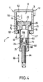
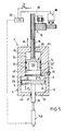
- the spring chamber 8 is now connected to at least one reserve space 46 (FIGS. 1, 2, 4 and 7) or 48 (FIGS. 5, 6 and 7) in such a way that in the compression end position of the separating piston 6, ie when after a maximum displacement in the direction of the spring chamber 8, it comes to rest against a mechanical stop 50, a certain minimum residual volume V res is still available for the compressible medium.
- This advantageously prevents the compressible medium in the spring chamber 8 from being compressed too much (to zero), as a result of which the pressure p 1 would rise to an unacceptably high level and the memory could burst.
- the reserve space 46 is now arranged on the separating piston side and is formed with a constant volume V res , determined once by a corresponding calculation, from a depression 52 which extends axially through the separating piston 6 into the separating piston rod 26.
- the reserve space is composed of the reserve space 46 on the side of the separating piston and a reserve space 48 on the cylinder side opposite this.
- This reserve space 46, 48 also has a constant volume V res .
- the separating piston-side reserve space 46 is formed by a recess 52 which extends axially into the separating piston 6 and the opposite reserve Veraum 48 of a cylinder chamber 54 adjoining the spring chamber 8 on the side opposite the separating piston 6.
- the separating piston rod 26 is hollow, in particular hollow cylindrical, to form the reserve space 46, and the reserve space 46 is at least one axial Passage 56 of the separating piston 6 is connected to the spring chamber 8.
- the volume of the reserve space 46 on the side of the separating piston or the volume of the reserve space 48 on the side opposite the separating piston 6 can be changed from outside using adjusting means 60.
- the adjusting means 60 have a control piston 62 which is guided axially displaceably within the hollow cylindrical separating piston rod 26.
- the control piston 62 is adjustable according to the invention either mechanically or by means of a pressure medium, in particular hydraulically. 4, mechanical adjustment is provided.
- the control piston 62 is connected on its side facing away from the separating piston 6 to a threaded spindle 64 which extends outwards through an internal thread at the end of the separating piston rod 26. This results in an axial adjustment of the control piston 62 in the double arrow direction 66 when the threaded spindle 64 rotates.
- control piston 62 On the side of the control piston 62 remote from the separating piston 6 there is a thread spindle 64 enclosing annular space 68 which is connected via at least one ventilation opening 70 with atmospheric pressure. For this reason, the control piston 62 is sealed against the inner wall of the hollow cylindrical piston rod 26 via a circumferential seal 72 designed as a gas seal.
- the actuating means 60 have a control piston 74 which is adjustably guided within the cylinder chamber 54.
- this control piston 74 is mechanically adjustable analogously to the embodiment according to FIG. 4, for which purpose it is connected on its side facing away from the separating piston 6 to a threaded spindle 76 which extends outwards through an internal thread of the cylinder 4.
- the threaded spindle 76 is connected to a rotary drive 78, shown only schematically, comprising a motor 80 and a gear 82.
- annular space 84 surrounding the threaded spindle 76 within the cylinder chamber 54 is in turn connected to the outside atmosphere via at least one ventilation opening 86, so that the control piston 74 is also equipped with a gas seal, which here consists of two peripheral seals 72.
- FIG. 6 corresponds essentially to that according to FIG. 5, but here a hydraulic adjustment of the control piston 74 is provided.
- a connection 90 opens into a pressure chamber 88 which is arranged on the side of the control piston 74 facing away from the separating piston 6 and which can optionally be connected to a pressure line P or a tank return line T of a hydraulic system via a line connection 92 and a switching valve 94.
- the hydraulic pressure is generated by a pump 96 and preferably in an additional one Chen memory 98 stored so that there is always a sufficient hydraulic pressure available.
- the control piston 74 is designed according to the invention as a pressure transducer, so that the hydraulic control pressure p3 is greater than the pneumatic pressure p1.
- control piston 74 can advantageously be equipped with a simplified peripheral seal 100 designed as an "oil seal". Analogous to the separating piston 6, this pressure difference in the area of the control piston 74 is achieved in that the control piston 74 is connected on its side remote from the spring chamber 8 to a control piston rod 102, which seals via a circumferential seal 104 from the cylinder 4 or the cylinder chamber 54 is led outside.
- control piston 62 or 74 has on its side facing the spring chamber 8 a recess 106, which also occurs when the control piston is adjusted 62 or 74 in the direction of the spring chamber 8 against a mechanical end stop 107 always ensures a minimum residual volume for the compressible medium.
- the separating piston 6 and / or the control piston 74 can be connected to (in each case) a displacement sensor 108, 110 which detects the piston position.
- the volume V res of the reserve space 48 can be adapted to certain conditions in dynamic operation via a computer 112 connected to the displacement sensor 108, 110.
- the detected position of the separating piston 6 allows a statement about the load or the suspension state.
- the ratio of V max / V res and p max / p can be made, that is, the Set and monitor the degree of impact or the spring characteristic.
- the adjusting means 60 are controlled by the computer 112, ie in the case of FIG. 5 the computer 112 controls the motor 80 of the rotary drive 78, and in the case of FIG. 6 the switching valve 94 is switched by the computer 112 to one of its two open positions .
- the piston accumulator 2 according to the invention in the embodiment according to FIGS. 7 and 8 is equipped with an integrated damping valve 28 which is arranged between the storage space 10 and its connection 16 and is adjustable in particular with regard to the damping effect.
- the damping valve 28 has a first valve chamber 120, into which the connection 16 opens, and a second valve chamber 122, which is connected to the storage space 10 via a channel 124 which is only shown in broken lines in FIG.
- the damping valve 28 in this case preferably consists of two individual throttle valves 124 and 126, namely a compression throttle valve 124 for damping the compression flow into the storage space 10 and a compression throttle valve 126 for damping the compression flow out of the storage space 10.
- the two valve chambers 120 and 122 are separated from one another by a partition 128, at least one throttle duct 130 extending through this partition 128 for each throttle valve 124 or 126.
- the throttle channels 130 are each equipped with a valve element for setting the damping.
- each valve element as the throttle channel 130 in the example shown each of a plurality of throttle channels 130, is at least at its outlet opening 132 for the hydraulic medium partially covered, one-sided clamped leaf spring element 134.
- the damping adjustment is made by varying the free leaf length or the clamping length 1 of the leaf spring element 134.
- a pressure element 136 which is movably guided along the leaf spring element 134 over this is expediently provided (see the double arrow 138 in FIG. 9) such that the leaf spring element 134 is clamped between the partition 128 and the pressure element 136 with the variable length 1.
- each throttle valve 124, 126 has a plurality of parallel throttle ducts 130 which are arranged on a circular arc and are each covered by an annular disk-shaped, radially slotted leaf spring element 134.
- the respective pressure element 136 is finger-like, projecting radially from a rotatable shaft, so that it rotates over the respective leaf spring element 134 when the shaft rotates. moved on a circular path. Further details on the design of the damping valve 28 are contained in the applicant's older German patent application P 39 25 520.4, to which reference is made here in full.
- the separating piston 6 has on the side of the storage space 10 a closure element 150 which is in a shut-off position displaced in the direction of an end stop 152 on the storage space side of the separating piston (see FIG. 11) closes the hydraulic connection 16 opening into the storage space 10 in such a way that a closed pressure space 154, completely filled with the hydraulic medium, is formed from a residual volume of the storage space 10.
- the closure element 150 is advantageously designed or mounted such that it is resilient in such a way that the separating piston 6 can be moved in the direction of the end stop 152 against a spring force beyond the shut-off position shown in FIG. 11.
- the hydraulic connection 16 arranged laterally on the cylinder 4 merges into an axial channel section 156 which opens into the area of the storage space 10 axially opposite the separating piston 6 in the axial direction and preferably centrally in the latter.
- the separating piston rod 26 extends through the axial channel section 156 such that it concentrically surrounds the separating piston rod 26 with an annular cross section.
- the closure element 150 of the separating piston 6 preferably has an annular disk element 160 which is arranged on the separating piston rod 26 to be resiliently movable in the axial direction and which, in the shut-off position, covers the mouth of the axial channel section 156 and seals the pressure chamber 154 via a seal 158 surrounding the mouth.
- the seal 158 is preferred arranged as an O-ring in an annular groove of the cylinder 4 surrounding the mouth of the channel section 156.
- Annular disk element 160 of the closure element 150 is connected to an annular sleeve 162 arranged displaceably on the separating piston rod 26.
- an annular gap formed between the separating piston rod 26 and the annular sleeve 162 is sealed according to the invention via a sealing ring 164.
- a compression spring 166 is arranged under prestress between the separating piston 6 and the closure element 150, ie between the separating piston 6 and preferably the annular disk element 160.
- This compression spring 166 is expediently designed as the separating piston rod 26 and the annular sleeve 162 concentrically surrounding spiral spring.
- the separating piston rod 26 for the closure element 150 has a stop 168 on its side facing away from the separating piston 6, which is formed in particular by a Seeger ring 170 seated in an annular groove of the separating piston rod 26.
- This stop 168 limits the movement of the closure element 150 in a direction remote from the separating piston 6.
- the stop 168 or the Seeger ring 170 is formed with a radial surface area that is smaller than the mouth of the channel section 156, so that in the shut-off position (FIG. 11) the Seeger ring 170 is arranged within the mouth area of the channel section 156. As a result, the annular disk element 160 can come into sealing contact with the seal 158.
- the separating piston 6 is at least in its shut-off position shown in FIG. 11, in which the closure element 150 closes the connection 16 or the channel section 156 and thereby forms the pressure chamber 154 slightly in both axial directions movable (see double arrow 172 in Fig. 11).
- This automatically sets a corresponding hydraulic pressure p2 due to the pneumatic pressure p1.
- the peripheral seal 20 of the separating piston 6 advantageously needs to be designed only for the differential pressure between p 1 and p 2.
- the annular disk element 160 can also be fixed in its inner ring area, e.g. cohesively, connected to the separating piston rod 26 and thereby be made of a resilient material, for example spring steel, so that it practically forms a kind of plate spring.
Landscapes
- Engineering & Computer Science (AREA)
- General Engineering & Computer Science (AREA)
- Mechanical Engineering (AREA)
- Physics & Mathematics (AREA)
- Acoustics & Sound (AREA)
- Aviation & Aerospace Engineering (AREA)
- Vehicle Body Suspensions (AREA)
Applications Claiming Priority (6)
| Application Number | Priority Date | Filing Date | Title |
|---|---|---|---|
| DE3936034 | 1989-10-28 | ||
| DE19893936034 DE3936034A1 (de) | 1989-10-28 | 1989-10-28 | Hydropneumatisches federungssystem |
| DE9002419U DE9002419U1 (de) | 1989-10-28 | 1990-03-02 | Hydropneumatischer Kolbenspeicher |
| DE9002419U | 1990-03-02 | ||
| DE9012936U | 1990-09-11 | ||
| DE9012936U DE9012936U1 (de) | 1990-09-11 | 1990-09-11 | Hydropneumatischer Kolbenspeicher |
Publications (2)
| Publication Number | Publication Date |
|---|---|
| EP0425876A2 true EP0425876A2 (fr) | 1991-05-08 |
| EP0425876A3 EP0425876A3 (en) | 1991-09-11 |
Family
ID=27200369
Family Applications (1)
| Application Number | Title | Priority Date | Filing Date |
|---|---|---|---|
| EP19900119695 Withdrawn EP0425876A3 (en) | 1989-10-28 | 1990-10-15 | Hydropneumatic piston accumulator |
Country Status (3)
| Country | Link |
|---|---|
| EP (1) | EP0425876A3 (fr) |
| JP (1) | JPH03157218A (fr) |
| BR (1) | BR9005450A (fr) |
Cited By (6)
| Publication number | Priority date | Publication date | Assignee | Title |
|---|---|---|---|---|
| WO1994008808A1 (fr) * | 1992-10-10 | 1994-04-28 | Hemscheidt Fahrwerktechnik Gmbh & Co. Kg | Systeme de suspension hydropneumatique |
| WO1997038239A1 (fr) * | 1996-04-09 | 1997-10-16 | Kinnarps Ab | Architecture de table |
| WO2000002743A1 (fr) * | 1998-07-08 | 2000-01-20 | Hydac Technology Gmbh | Systeme de regulation de pression |
| DE102016114733A1 (de) * | 2016-08-09 | 2018-02-15 | Marco Systemanalyse Und Entwicklung Gmbh | Druckübersetzer |
| CN116877618A (zh) * | 2023-07-18 | 2023-10-13 | 泉州市博汉机械股份有限公司 | 一种可调节阻尼的平衡杆 |
| US20250162368A1 (en) * | 2023-11-20 | 2025-05-22 | Hl Mando Corporation | Accumulator and vehicle suspension system including the same |
Families Citing this family (2)
| Publication number | Priority date | Publication date | Assignee | Title |
|---|---|---|---|---|
| JP2009228724A (ja) * | 2008-03-21 | 2009-10-08 | Kayaba Ind Co Ltd | 緩衝器 |
| CN113071280A (zh) * | 2021-04-01 | 2021-07-06 | 内蒙古铁辰智能装备有限公司 | 一种大吨位矿用车后悬架系统 |
Family Cites Families (13)
| Publication number | Priority date | Publication date | Assignee | Title |
|---|---|---|---|---|
| GB337855A (en) * | 1929-08-16 | 1930-11-13 | Mactaggart Scott & Company Ltd | Improvements in air loaded and like accumulators |
| GB755342A (en) * | 1954-03-12 | 1956-08-22 | Keelavite Co Ltd | Improvements in or relating to free piston hydraulic accumulators |
| GB821697A (en) * | 1956-05-31 | 1959-10-14 | Loewy Eng Co Ltd | Hydraulic accumulator |
| GB864361A (en) * | 1957-09-04 | 1961-04-06 | Gratzmuller Jean Louis | Improvements in or relating to hydraulic power systems |
| DE1802193A1 (de) * | 1968-10-10 | 1970-08-27 | Auto Teile Praez Kg | Hydropneumatische Gasfeder,insbesondere zum Abstuetzen und Verstellen von Krankenbetten od.dgl. |
| FR2076812A5 (fr) * | 1970-01-29 | 1971-10-15 | Gratzmuller J | |
| NL7402566A (en) * | 1974-02-26 | 1975-08-28 | Yamaha Motor Nv | Hydraulic pressure accumulator - has gas chamber pressure variable independent of movement of partition between it and fluid |
| FR2461852A1 (fr) * | 1979-07-17 | 1981-02-06 | Messier Hispano Sa | Perfectionnements aux amortisseurs et amortisseurs-verins notamment pour trains d'atterrissage d'aerodyne |
| EP0173020A2 (fr) * | 1984-06-28 | 1986-03-05 | Stephen W. Simons | Système amortisseur anticavitation pour fourche avant de motocyclette |
| DE3427902A1 (de) * | 1984-07-28 | 1986-02-13 | Franz Dr.-Ing. 7530 Pforzheim Tuczek | Steuerung von hydropneumatischen federelementen, insbesondere fuer kraftfahrzeuge |
| DE3503152A1 (de) * | 1985-01-31 | 1986-08-14 | Daimler-Benz Ag, 7000 Stuttgart | Schwingungsdaempfer fuer fahrzeuge |
| FR2601097B1 (fr) * | 1986-07-07 | 1990-07-06 | Messier Hispano Bugatti Sa | Amortisseur a adaptation de course residuelle |
| EP0318817A3 (fr) * | 1987-11-28 | 1990-05-30 | Hermann Hemscheidt Maschinenfabrik GmbH & Co. | Amortisseur de chocs et de vibrations hydropneumatique à tube intérieur |
-
1990
- 1990-10-15 EP EP19900119695 patent/EP0425876A3/de not_active Withdrawn
- 1990-10-25 JP JP28600690A patent/JPH03157218A/ja active Pending
- 1990-10-26 BR BR9005450A patent/BR9005450A/pt unknown
Cited By (7)
| Publication number | Priority date | Publication date | Assignee | Title |
|---|---|---|---|---|
| WO1994008808A1 (fr) * | 1992-10-10 | 1994-04-28 | Hemscheidt Fahrwerktechnik Gmbh & Co. Kg | Systeme de suspension hydropneumatique |
| WO1997038239A1 (fr) * | 1996-04-09 | 1997-10-16 | Kinnarps Ab | Architecture de table |
| WO2000002743A1 (fr) * | 1998-07-08 | 2000-01-20 | Hydac Technology Gmbh | Systeme de regulation de pression |
| DE102016114733A1 (de) * | 2016-08-09 | 2018-02-15 | Marco Systemanalyse Und Entwicklung Gmbh | Druckübersetzer |
| CN116877618A (zh) * | 2023-07-18 | 2023-10-13 | 泉州市博汉机械股份有限公司 | 一种可调节阻尼的平衡杆 |
| US20250162368A1 (en) * | 2023-11-20 | 2025-05-22 | Hl Mando Corporation | Accumulator and vehicle suspension system including the same |
| US12496864B2 (en) * | 2023-11-20 | 2025-12-16 | Hl Mando Corporation | Accumulator and vehicle suspension system including the same |
Also Published As
| Publication number | Publication date |
|---|---|
| JPH03157218A (ja) | 1991-07-05 |
| EP0425876A3 (en) | 1991-09-11 |
| BR9005450A (pt) | 1991-09-17 |
Similar Documents
| Publication | Publication Date | Title |
|---|---|---|
| DE19652819C2 (de) | Hydraulikstoßdämpfer mit steuerbarer Dämpfungskraft | |
| EP0662882B1 (fr) | Systeme de suspension hydropneumatique | |
| DE102011004962B4 (de) | Stoßdämpfer | |
| DE3503152C2 (fr) | ||
| DE69005747T2 (de) | Ventil für hydraulische Flüssigkeit und ein mit einem solchen Ventil ausgerüsteter Dämpfer. | |
| DE1775415A1 (de) | Schwingungsdaempfer,Federbein oder hydropneumatische Federung mit belastungsabhaengiger Schwingungsdaempfung | |
| DE19901639B4 (de) | Druckabhängig reagierendes Ventil, insbesondere für einen Schwingungsdämpfer | |
| DE1555311A1 (de) | In Abhaengigkeit von der Federbelastung selbsttaetig regelbarer Schwingungsdaempfer | |
| DE3526156C2 (fr) | ||
| DE4116399C2 (de) | Kolbenzylindereinheit insbesondere zur Verwendung als Federbein in Fahrzeug-Federungssystemen | |
| DE102013011653A1 (de) | Hydraulisch gedämpfte Lagereinrichtung | |
| DE3613677A1 (de) | Stoss- und schwingungsdaemfpungssystem | |
| DE102006006789B4 (de) | Hydraulische Vorrichtung mit eingebautem freien Kolben | |
| DE1936858C3 (de) | Selbstpumpendes hydraulisches Federbein mit innerer Niveauregelung für Fahrzeuge | |
| EP0831245B1 (fr) | Amortisseur de chocs industriel | |
| DE112021003611T5 (de) | Stossdämpfer | |
| DE2206771A1 (de) | Hochdruckdichtung mit dem o-ring angepasster abstuetzflaeche und kantenbelastetem dichtring | |
| DE3619402C2 (fr) | ||
| DE3601712A1 (de) | Einrichtung zur kontrolle unerwuenschter bewegungen und auslenkungen | |
| DE4008831A1 (de) | Hydropneumatisches federungssystem | |
| DE3935608A1 (de) | Kolbenzylindereinheit | |
| DE4221126C2 (de) | Hydropneumatisches Federungssystem | |
| DE4003200A1 (de) | Hydropneumatisches federungssystem | |
| EP0529320A1 (fr) | Système de ressort oléopneumatique pour l'essieu relevable d'un véhicule | |
| DE3601445C2 (fr) |
Legal Events
| Date | Code | Title | Description |
|---|---|---|---|
| PUAI | Public reference made under article 153(3) epc to a published international application that has entered the european phase |
Free format text: ORIGINAL CODE: 0009012 |
|
| AK | Designated contracting states |
Kind code of ref document: A2 Designated state(s): BE DE ES FR GB IT NL SE |
|
| PUAL | Search report despatched |
Free format text: ORIGINAL CODE: 0009013 |
|
| AK | Designated contracting states |
Kind code of ref document: A3 Designated state(s): BE DE ES FR GB IT NL SE |
|
| 17P | Request for examination filed |
Effective date: 19920117 |
|
| 17Q | First examination report despatched |
Effective date: 19920330 |
|
| STAA | Information on the status of an ep patent application or granted ep patent |
Free format text: STATUS: THE APPLICATION IS DEEMED TO BE WITHDRAWN |
|
| 18D | Application deemed to be withdrawn |
Effective date: 19920811 |