EP0425914A2 - Variateur continu de vitesse à galet de friction - Google Patents
Variateur continu de vitesse à galet de friction Download PDFInfo
- Publication number
- EP0425914A2 EP0425914A2 EP90120025A EP90120025A EP0425914A2 EP 0425914 A2 EP0425914 A2 EP 0425914A2 EP 90120025 A EP90120025 A EP 90120025A EP 90120025 A EP90120025 A EP 90120025A EP 0425914 A2 EP0425914 A2 EP 0425914A2
- Authority
- EP
- European Patent Office
- Prior art keywords
- toric
- trunnions
- traction
- discs
- trunnion
- Prior art date
- Legal status (The legal status is an assumption and is not a legal conclusion. Google has not performed a legal analysis and makes no representation as to the accuracy of the status listed.)
- Granted
Links
- 230000005540 biological transmission Effects 0.000 title claims abstract description 46
- 230000033001 locomotion Effects 0.000 claims abstract description 10
- 230000000977 initiatory effect Effects 0.000 claims abstract description 4
- 239000012530 fluid Substances 0.000 description 3
- 230000006835 compression Effects 0.000 description 1
- 238000007906 compression Methods 0.000 description 1
- 150000002500 ions Chemical class 0.000 description 1
- 239000002184 metal Substances 0.000 description 1
- 230000007935 neutral effect Effects 0.000 description 1
- 229920000136 polysorbate Polymers 0.000 description 1
Images


Classifications
-
- F—MECHANICAL ENGINEERING; LIGHTING; HEATING; WEAPONS; BLASTING
- F16—ENGINEERING ELEMENTS AND UNITS; GENERAL MEASURES FOR PRODUCING AND MAINTAINING EFFECTIVE FUNCTIONING OF MACHINES OR INSTALLATIONS; THERMAL INSULATION IN GENERAL
- F16H—GEARING
- F16H15/00—Gearings for conveying rotary motion with variable gear ratio, or for reversing rotary motion, by friction between rotary members
- F16H15/02—Gearings for conveying rotary motion with variable gear ratio, or for reversing rotary motion, by friction between rotary members without members having orbital motion
- F16H15/04—Gearings providing a continuous range of gear ratios
- F16H15/06—Gearings providing a continuous range of gear ratios in which a member A of uniform effective diameter mounted on a shaft may co-operate with different parts of a member B
- F16H15/32—Gearings providing a continuous range of gear ratios in which a member A of uniform effective diameter mounted on a shaft may co-operate with different parts of a member B in which the member B has a curved friction surface formed as a surface of a body of revolution generated by a curve which is neither a circular arc centered on its axis of revolution nor a straight line
- F16H15/36—Gearings providing a continuous range of gear ratios in which a member A of uniform effective diameter mounted on a shaft may co-operate with different parts of a member B in which the member B has a curved friction surface formed as a surface of a body of revolution generated by a curve which is neither a circular arc centered on its axis of revolution nor a straight line with concave friction surface, e.g. a hollow toroid surface
- F16H15/38—Gearings providing a continuous range of gear ratios in which a member A of uniform effective diameter mounted on a shaft may co-operate with different parts of a member B in which the member B has a curved friction surface formed as a surface of a body of revolution generated by a curve which is neither a circular arc centered on its axis of revolution nor a straight line with concave friction surface, e.g. a hollow toroid surface with two members B having hollow toroid surfaces opposite to each other, the member or members A being adjustably mounted between the surfaces
Definitions
- the invention relates to an infinitely variable traction roller transmission in which power is transmitted through traction rollers pivotally supported between toric input and output discs.
- the traction rollers are mounted on support structures which, when pivoted, cause engagement of the traction rollers with the toric discs in circles of varying diameters depending on the desired transmission ratio.
- the pivotal traction roller support structures are so supported that they can be moved axially for initiating a change in the transmission ratio.
- two traction rollers may be supported opposite one another by flexible tension sheets as shown in U.S. Patent 4,086,820 which issued May 2, 1978 to Charles E. Kraus.
- each traction roller is supported by a pivotal support trunnion which has support rollers disposed at opposite ends thereof and supported on partial circular tracks disposed on the housing's inner surface for direct trunnion support.
- the traction rollers are supported on the pivot trunnions by force transmitting means which, for inexpensive transmissions, include stacks of Belleville springs.
- the housing tracks may have a center of curvature which is slightly off-set with regard to the pivot axis of the trunnions in order to provide greater compression of the Belleville spring, that is, greater disc engagement forces in one pivotal end position of the pivot trunnions than in their opposite pivotal end positions.
- the arrangement according to applicant's application E.P. 89118275.0/0365872 utilizes a single support roller for each trunnion which is received in a partial circular track section mounted in the housing for forcing the trunnion and the associated traction roller into firm engagement with the toric discs for permitting transmission of motion therebetween.
- An axially projecting control end of each trunnion is supported so as to be slightly movable in a plane normal to the axis of the toric discs, the control ends of the trunnions having means associated therewith for tilting the trunnions in unison in said plane for the initiation of a transmission ratio change.
- roller engagement forces are obtained by wedges adapted to force the track section toward the toric discs so as to generate the engagement forces for the traction rollers with the toric discs.
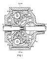
- a simple traction roller transmission as shown in Fig. 1 consists of a housing 10 having coaxial input and output shafts 12 and 14, respectively, rotatably supported therein by bearings 16 and 18. Associated with the input and output shafts 12, 14 are toric discs 20, 22 which are so arranged opposite one another that a toric cavity 24 of circular cross-section is defined therebetween. Within the toric cavity 24 traction rollers 26, 28 are rotatably supported in engagement with the toric traction discs 20, 22.
- the traction rollers 26, 28 are supported in the housing 10 by pivot trunnions 30 and 32 which are pivotally supported by way of trunnion rollers 34 and 36 running on hard metal track members 38, 40 re ceived in track cavities 42, 44 formed in the housing 10.
- Each of the pivot trunnions 30, 32 carries a traction roller bearing 46 for rotatably supporting the associated traction rollers 26, 28 which are forced into firm engagement with the traction discs 20 and 22 by way of the trunnion rollers 34, 36, the traction discs 20 and 22 being axially supported by axial thrust bearings 48 and 50.
- the engagement forces of the traction rollers 26, 28 with the toric traction discs 20, 22 depend on the loading applied by the track members 38, 40.
- the track members 38 have partial circular support grooves 54 which have centers of curvature disposed on control axes which are tangential to the center circle of the toric cavity 24 such that the pivot trunnions 30, 32 are supported so as to pivot about such control axes.
- the circular support grooves 54 in the track members 38, 40 may be slightly eccentric with respect to the center circle of curvature of the toric cavity 24 in order to provide larger contact forces for the traction rollers in one pivotal end position of the pivot trunnions 30 and 32, specifically, in the position for lowest output shaft speed and highest output shaft torque as shown in Fig. 1.
- Fig. 2 shows the transmission without a housing.
- the track members 38 and 40 are pivotally supported at one end by pivotal supports or by hinges 62 as shown in the drawings. At their other ends they are hinged to leverage arms 64 which abut the support members 56 and 58.
- the support members 56 and 58 carry operating cylinders 66 provided with pistons 68 and piston rods 70 which are linked to the control ends of the trunnions 30 and 32.
- the trunnions 30 and 32 carry the traction rollers 26 and 28 as mentioned earlier and are forced toward the toric discs 20 and 22 by the track members 38 and 40 with engagement forces which depend on the control forces applied by the pistons 68 and piston rods 70 to the adjacent control ends of the trunnions 30 and 32 and which are generated by the reaction forces transmitted from the cylinder 66 to the cylinder support ends of the leverage arms 64.
- the leverage arms 64 have force control surfaces 72 which provide for some leverage to multiply the traction roller engagement forces applied to the trunnions 30 and 32 by way of the trunnion rollers 34 and 36.
- the force control surfaces 72 of the leverage arm 64 are somewhat curved at their opposite ends 74 and 76 to provide for reduced wear at their tilting edges.
- the leverage arms 64 are preferably forked with the cylinders 66 received between the forked arms and linked to their free ends.
- retaining rods 60 extending between the support members 56 and 58 at one side of the transmission and three at the opposite side thereof, a center retaining rod and two outer retaining rods.
- the trunnions 30, 32 are provided with grooves 78 which receive the center rod 60 and which are so shaped and sized that the pivotal end positions of the trunnions is limited by their engagement of the center rod 60.
- the narrowest center sections 79 of the grooves 78 are disposed in a plane receiving the pivot axis of the trunnions.
- the traction roller bearings 46 as shown in Fig. 2 are such that they permit inward movement of the traction rollers into engagement with the toric discs by the force of the Belleville springs 80 applied through the auxiliary bearings 82 in order to keep the traction rollers 26, 28 in engagement with the toric discs 20, 22 even when no torque is transmitted through the transmission.
- admission of pressurized fluid to the cylinders 66 at the appropriate side of the piston 68 is controlled so as to tilt the two trunnions 30, 32 slightly in the same circumferential sense with respect to the axis of the toric discs 20, 22 such that, upon rotation of the toric discs 20, 22, the traction rollers 26, 28 will roll to larger circles of engagement with one and smaller circles of engagement with the other of the toric discs 20, 22.
- the trunnions 30, 32 are returned to their neutral positions in which the momentary transmission ratio is maintained.
- the arrangement described requires only one hydraulic cylinder 60 and piston 68 for the support of the trunnion control ends and for generating the traction roller engagement forces.
- a single cylinder would be sufficient for both trunnions 30, 32 and trunnion supports.
- the cylinder 60 furthermore requires only low pressure operating fluid sufficient to control trunnion movement while nevertheless providing increased but proportional forces to the trunnions 30, 32 for roller engagement with the toric discs 20, 22.
- the track members 38, 40 which have the tracks 54 formed therein are preferably wide enough so that they can easily provide support for the trunnions 30, 32 in any pivot position of the trunnions 30, 32. If they are wide enough they may be supported for pivotal movement simply by a fulcrum structure such that no hinged supports are needed.
- the transmission assembly as shown in Fig. 2 is disposed in a housing, that is, its own housing or a drive housing in connection with which the transmission is utilized.
- the assembly is attached to the housing preferably by bolts extending into the bases, but this is not shown in the drawings.
- the transmission as described is quite simple with relatively few parts. It requires operating fluid of only relatively low pressure to provide the different forces necessary for operation and in any case, the whole transmission is easily replaceable in case of failure.
Landscapes
- Engineering & Computer Science (AREA)
- General Engineering & Computer Science (AREA)
- Mechanical Engineering (AREA)
- Friction Gearing (AREA)
Applications Claiming Priority (2)
| Application Number | Priority Date | Filing Date | Title |
|---|---|---|---|
| US07/428,974 US4996891A (en) | 1989-10-30 | 1989-10-30 | Infinitely variable traction roller transmission |
| US428974 | 1989-10-30 |
Publications (3)
| Publication Number | Publication Date |
|---|---|
| EP0425914A2 true EP0425914A2 (fr) | 1991-05-08 |
| EP0425914A3 EP0425914A3 (en) | 1991-07-10 |
| EP0425914B1 EP0425914B1 (fr) | 1994-06-22 |
Family
ID=23701211
Family Applications (1)
| Application Number | Title | Priority Date | Filing Date |
|---|---|---|---|
| EP90120025A Expired - Lifetime EP0425914B1 (fr) | 1989-10-30 | 1990-10-19 | Variateur continu de vitesse à galet de friction |
Country Status (4)
| Country | Link |
|---|---|
| US (1) | US4996891A (fr) |
| EP (1) | EP0425914B1 (fr) |
| DE (2) | DE69010142D1 (fr) |
| ES (1) | ES2055271T3 (fr) |
Cited By (2)
| Publication number | Priority date | Publication date | Assignee | Title |
|---|---|---|---|---|
| WO2001046604A3 (fr) * | 1999-12-21 | 2001-12-27 | Zahnradfabrik Friedrichshafen | Boite de vitesses toroidale variable |
| WO2005017391A1 (fr) * | 2003-08-15 | 2005-02-24 | Getrag Getriebe- Und Zahnradfabrik Hermann Hagenmeyer Gmbh & Cie Kg | Variateur et systeme de variateur |
Families Citing this family (3)
| Publication number | Priority date | Publication date | Assignee | Title |
|---|---|---|---|---|
| US5085089A (en) * | 1991-02-06 | 1992-02-04 | Excelermatic Inc. | Infinitely variable traction roller transmission |
| AU7707100A (en) * | 1999-09-20 | 2001-04-24 | Transmission Technologies Corporation | Dual strategy control for a toroidal drive type continuously variable transmission |
| CA2401474C (fr) * | 2002-09-05 | 2011-06-21 | Ecole De Technologie Superieure | Commande de cabestan de courroie pour transmission par courroie torique |
Family Cites Families (7)
| Publication number | Priority date | Publication date | Assignee | Title |
|---|---|---|---|---|
| US4086820A (en) * | 1976-06-25 | 1978-05-02 | Excelermatic, Inc. | Infinitely variable traction roller transmission |
| US4484487A (en) * | 1983-01-03 | 1984-11-27 | Excelermatic Inc. | Hydraulically controlled infinitely variable traction roller transmission |
| US4858484A (en) * | 1987-10-26 | 1989-08-22 | Excelermatic Inc. | Infinitely variable traction roller transmission |
| US4830578A (en) * | 1987-10-26 | 1989-05-16 | Excelermatic Inc. | Hydraulic control arrangement for an infinitely variable transmission drive |
| JPH0637223Y2 (ja) * | 1988-05-27 | 1994-09-28 | 日産自動車株式会社 | 摩擦車式無段変速機構 |
| US4964312A (en) * | 1988-10-17 | 1990-10-23 | Excelermatic Inc. | Infinitely variable traction roller transmission |
| US4911030A (en) * | 1989-01-30 | 1990-03-27 | Excelermatic Inc. | Traction roller transmission ratio control arrangement |
-
1989
- 1989-10-30 US US07/428,974 patent/US4996891A/en not_active Expired - Lifetime
-
1990
- 1990-10-19 ES ES90120025T patent/ES2055271T3/es not_active Expired - Lifetime
- 1990-10-19 DE DE69010142A patent/DE69010142D1/de not_active Expired - Fee Related
- 1990-10-19 EP EP90120025A patent/EP0425914B1/fr not_active Expired - Lifetime
- 1990-10-19 DE DE69010142T patent/DE69010142T4/de not_active Expired - Lifetime
Cited By (4)
| Publication number | Priority date | Publication date | Assignee | Title |
|---|---|---|---|---|
| WO2001046604A3 (fr) * | 1999-12-21 | 2001-12-27 | Zahnradfabrik Friedrichshafen | Boite de vitesses toroidale variable |
| US6689013B1 (en) | 1999-12-21 | 2004-02-10 | Zf Friedrichshafen Ag | Continuously variable friction gear transmission |
| WO2005017391A1 (fr) * | 2003-08-15 | 2005-02-24 | Getrag Getriebe- Und Zahnradfabrik Hermann Hagenmeyer Gmbh & Cie Kg | Variateur et systeme de variateur |
| US7211023B2 (en) | 2003-08-15 | 2007-05-01 | Getrag Getriebe-Und Zahradfabrik Hermann Hagenmeyer Gmbh & Cie Kg | Variator and variator arrangement |
Also Published As
| Publication number | Publication date |
|---|---|
| EP0425914A3 (en) | 1991-07-10 |
| DE69010142T4 (de) | 1995-02-02 |
| EP0425914B1 (fr) | 1994-06-22 |
| ES2055271T3 (es) | 1994-08-16 |
| US4996891A (en) | 1991-03-05 |
| DE69010142T2 (de) | 1994-10-13 |
| DE69010142D1 (de) | 1994-07-28 |
Similar Documents
| Publication | Publication Date | Title |
|---|---|---|
| EP0365872B1 (fr) | Variateur continu de vitesse à rouleaux de traction | |
| US5020384A (en) | Infinitely variable traction roller transmission | |
| US5048359A (en) | Toroidal continuously variable transmission | |
| US4275610A (en) | Infinitely variable traction roller transmission | |
| WO1994013978A1 (fr) | Dispositif de charge pour transmission variable en continu | |
| EP0429938B1 (fr) | Variateur continu de vitesse à rouleaux de traction | |
| US4911030A (en) | Traction roller transmission ratio control arrangement | |
| EP0425914A2 (fr) | Variateur continu de vitesse à galet de friction | |
| EP0400187B1 (fr) | Variateur continu de vitesse à rouleaux de traction | |
| US4694704A (en) | Infinitely variable traction roller transmission | |
| JPH0247619B2 (fr) | ||
| US5085089A (en) | Infinitely variable traction roller transmission | |
| US4537086A (en) | Infinitely variable toric transmission | |
| EP0637705B1 (fr) | Variateur continu de vitesse à rouleaux de traction | |
| EP0971159B1 (fr) | Transmission continue variable à rouleaux de friction | |
| US5697863A (en) | Extended life infinitely variable traction roller transmission with different toric traction roller disks | |
| JP2001304366A (ja) | トロイダル型無段変速機 | |
| JPH11141635A (ja) | トロイダル型無段変速機 | |
| EP1611372B1 (fr) | Transmission par traction a roulement toroidal | |
| CA1149642A (fr) | Organe transmetteur de couple pour transmission motrices, et methode pour engendrer un effort de friction normal | |
| JPH0814350A (ja) | トロイダル型無段変速機 | |
| JP3651156B2 (ja) | トロイダル型無段変速機 | |
| US4454782A (en) | Torque transmitting body for traction drive transmissions and normal friction force developing method | |
| JPH09269040A (ja) | トロイダル型無段変速機 | |
| JP2004011795A (ja) | トロイダル型無段変速機 |
Legal Events
| Date | Code | Title | Description |
|---|---|---|---|
| PUAI | Public reference made under article 153(3) epc to a published international application that has entered the european phase |
Free format text: ORIGINAL CODE: 0009012 |
|
| 17P | Request for examination filed |
Effective date: 19901206 |
|
| AK | Designated contracting states |
Kind code of ref document: A2 Designated state(s): DE ES FR GB IT SE |
|
| PUAL | Search report despatched |
Free format text: ORIGINAL CODE: 0009013 |
|
| AK | Designated contracting states |
Kind code of ref document: A3 Designated state(s): DE ES FR GB IT SE |
|
| 17Q | First examination report despatched |
Effective date: 19930521 |
|
| GRAA | (expected) grant |
Free format text: ORIGINAL CODE: 0009210 |
|
| AK | Designated contracting states |
Kind code of ref document: B1 Designated state(s): DE ES FR GB IT SE |
|
| REF | Corresponds to: |
Ref document number: 69010142 Country of ref document: DE Date of ref document: 19940728 |
|
| ITF | It: translation for a ep patent filed | ||
| REG | Reference to a national code |
Ref country code: ES Ref legal event code: FG2A Ref document number: 2055271 Country of ref document: ES Kind code of ref document: T3 |
|
| ET | Fr: translation filed | ||
| EAL | Se: european patent in force in sweden |
Ref document number: 90120025.3 |
|
| PLBE | No opposition filed within time limit |
Free format text: ORIGINAL CODE: 0009261 |
|
| STAA | Information on the status of an ep patent application or granted ep patent |
Free format text: STATUS: NO OPPOSITION FILED WITHIN TIME LIMIT |
|
| 26N | No opposition filed | ||
| PGFP | Annual fee paid to national office [announced via postgrant information from national office to epo] |
Ref country code: SE Payment date: 19950905 Year of fee payment: 6 |
|
| PGFP | Annual fee paid to national office [announced via postgrant information from national office to epo] |
Ref country code: FR Payment date: 19950922 Year of fee payment: 6 |
|
| PGFP | Annual fee paid to national office [announced via postgrant information from national office to epo] |
Ref country code: ES Payment date: 19961002 Year of fee payment: 7 |
|
| PG25 | Lapsed in a contracting state [announced via postgrant information from national office to epo] |
Ref country code: SE Effective date: 19961020 |
|
| PG25 | Lapsed in a contracting state [announced via postgrant information from national office to epo] |
Ref country code: FR Effective date: 19970630 |
|
| EUG | Se: european patent has lapsed |
Ref document number: 90120025.3 |
|
| REG | Reference to a national code |
Ref country code: FR Ref legal event code: ST |
|
| PG25 | Lapsed in a contracting state [announced via postgrant information from national office to epo] |
Ref country code: ES Free format text: LAPSE BECAUSE OF NON-PAYMENT OF DUE FEES Effective date: 19971020 |
|
| PGFP | Annual fee paid to national office [announced via postgrant information from national office to epo] |
Ref country code: GB Payment date: 19971020 Year of fee payment: 8 |
|
| PGFP | Annual fee paid to national office [announced via postgrant information from national office to epo] |
Ref country code: DE Payment date: 19981017 Year of fee payment: 9 |
|
| PG25 | Lapsed in a contracting state [announced via postgrant information from national office to epo] |
Ref country code: GB Free format text: LAPSE BECAUSE OF NON-PAYMENT OF DUE FEES Effective date: 19981019 |
|
| GBPC | Gb: european patent ceased through non-payment of renewal fee |
Effective date: 19981019 |
|
| PG25 | Lapsed in a contracting state [announced via postgrant information from national office to epo] |
Ref country code: DE Free format text: LAPSE BECAUSE OF NON-PAYMENT OF DUE FEES Effective date: 20000801 |
|
| REG | Reference to a national code |
Ref country code: ES Ref legal event code: FD2A Effective date: 19981113 |
|
| PG25 | Lapsed in a contracting state [announced via postgrant information from national office to epo] |
Ref country code: IT Free format text: LAPSE BECAUSE OF NON-PAYMENT OF DUE FEES;WARNING: LAPSES OF ITALIAN PATENTS WITH EFFECTIVE DATE BEFORE 2007 MAY HAVE OCCURRED AT ANY TIME BEFORE 2007. THE CORRECT EFFECTIVE DATE MAY BE DIFFERENT FROM THE ONE RECORDED. Effective date: 20051019 |