EP0425940A2 - Zünder für rotierendes Geschoss, mit Gerät zur Bestimmung der Anwesenheit eines Ziels - Google Patents
Zünder für rotierendes Geschoss, mit Gerät zur Bestimmung der Anwesenheit eines Ziels Download PDFInfo
- Publication number
- EP0425940A2 EP0425940A2 EP90120114A EP90120114A EP0425940A2 EP 0425940 A2 EP0425940 A2 EP 0425940A2 EP 90120114 A EP90120114 A EP 90120114A EP 90120114 A EP90120114 A EP 90120114A EP 0425940 A2 EP0425940 A2 EP 0425940A2
- Authority
- EP
- European Patent Office
- Prior art keywords
- radiation
- lens
- fact
- fuse according
- projectile
- Prior art date
- Legal status (The legal status is an assumption and is not a legal conclusion. Google has not performed a legal analysis and makes no representation as to the accuracy of the status listed.)
- Withdrawn
Links
Images


Classifications
-
- F—MECHANICAL ENGINEERING; LIGHTING; HEATING; WEAPONS; BLASTING
- F42—AMMUNITION; BLASTING
- F42C—AMMUNITION FUZES; ARMING OR SAFETY MEANS THEREFOR
- F42C13/00—Proximity fuzes; Fuzes for remote detonation
- F42C13/02—Proximity fuzes; Fuzes for remote detonation operated by intensity of light or similar radiation
Definitions
- the present invention relates to a fuse for a rotating projectile, including a device for detecting the presence of the target in the region of effective action of the projectile, to control a device for triggering detonation of the projectile.
- the points at which detonation has maximum effectiveness lie on a single straight line having its origin at the target and forming a predetermined angle with the said trajectory.
- the detection device must therefore define the point of intersection of this straight line with the trajectory of the projectile.
- this detection is effected by the emission of electromagnetic waves and detection of the Doppler effect in the return or echo signal, that is to say in the envelope of the waves reflected from the target. Since the emission of such waves is generally effected in lobes having a low directionality, this echo can in reality define a plurality of detonation positions distributed about the optimum point in a Gaussian manner, that is to say with a high dispersion, so that the effectiveness of the detonation triggered under the control of this detector can be very low.
- the object of the present invention is that of creating a fuse in which the detector device allows the optimum position for detonation to be determined with extreme precision and which will be of maximum simplicity and reliability of operation.
- the fuse according to the invention which is characterised by the fact that the said detector device includes sensor means sensitive to radiation in the infra-red region of the electromagnetic spectrum emitted by the target, and a single convex lens for receiving the said radiation and directing it to the said sensor means.
- a projectile for example an artillery projectile is generally indicated with the reference numeral 10, which projectile follows a trajectory 11 which, for a certain region about the position of the projectile 10 along this trajectory, can be considered as rectilinear.
- the projectile 10 also has a rotary motion about its axis, and therefore about the trajectory 11, as is known for example for projectiles from guns having rifled barrels.
- the reference numeral 12 indicates a target which can be stationary or moving. Considering, for simplicity, the target 12 as a point, in each instant there exists a single plane passing through the trajectory 11 and through the target point 12. In Figure 1 this plane is represented with a double dot chain line and is indicated with the reference numeral 13. In the plane 13 the points of detonation at which maximum effectiveness of the projectile 10 is achieved lie on a single straight line 14 having its origin at the target point 12, which intersects the trajectory 11 at a point 15 and forms with it an angle ⁇ of predetermined size.
- the projectile 10 is provided with a fuse 16 which is adapted to trigger detonation thereof and includes a device, generally indicated with the reference numeral 17 ( Figure 3) for detecting the presence of the target 12 ( Figure 1) and a device for controlling triggering of the detonator generally indicated 18 in Figure 3.
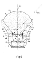
- the device 17 essentially comprises a lens 19 having a convex external surface 21 and a flat internal surface 22.
- the two surfaces 21 and 22 are connected by alateral frustoconical surface 23 by means of which the lens 19 is housed in a frusto-conical seat 24 in a support body 25.
- This has an outer surface formed as a surface of revolution about the optical axis 26 of the lens 19.
- the seat 24 is such as to leave exposed an annular region 27 of the surface 23 adjacent the flat surface 22.
- the outer surface 21 is substantially spherical with its centre at the point 28 ( Figure 4) and has a radius of curvature such as to be able to receive electromagnetic radiation coming from a wide field of view about the optical axis 26 of the lens 19, which coincides with the trajectory 11 ( Figure 1).
- the field of view of the fuse 16 is therefore represented by a cone 29 coaxial with the trajectory 11, which is indicated in Figures 1 and 2 with solid lines the cross-section through which, on a plane 31 normal to the axis 25, is indicated with the reference numeral 32.
- Radiation incident on each zone of the outer surface 21 ( Figure 4) of the lens 19 includes a principle ray 33 perpendicular to the surface 21 itself, and a bundle of rays 34 parallel to the principle ray 33.
- the parallel rays of each bundle 34 which are incident in the region of the point of intersection of the ray 33 with the surface 21, because of the refraction of the lens 19, converge at the same focus 36 so that they behave in a manner almost equal to that of the axial ray, that is they are effectively paraxial.
- the focal length of the lens 19 is therefore indicated as a paraxial focal length.
- the lens 19 has a thickness dimensioned in such a way that the path of a predetermined principle ray 33 through the lens 19 itself is equal to the paraxial focal length, and the associated focus 36a falls on the annular zone 27.
- other optical paths have been illustrated, which terminate on the flat surface 22 and on the conical surface 23 respectively.
- the detector device 17 includes means for selectively blocking rays refracted through the lens 19. These blocking means comprise the conical surface of the seat 24 of the support 25, which is opaque and therefore non-reflecting, so that it blocks the rays coming from outside the cone 29, for example those coming from the direction c.
- the blocking means further include a grid constituted by an opaque plate 37 which is disposed in contact with the flat surface 22 of the lens 19.
- the plate 37 ( Figure 3) includes a central portion 38 adapted to block the whole of the radiation refracted onto the flat surface 22, that is the rays coming from a central portion of the cone 29, for example those coming from the direction b ( Figure 4).
- the plate 37 further includes a portion 39 outside the flat surface 22 of the lens 19 and provided with a series of apertures 41 equidistant from one another.
- the apertures 41 can have a substantially square form and there may be four of them at 900 from one another.
- the apertures 41 are adapted to allow the selective passage of radiation along optical paths incident on the zone 27 of the conical surface 23.
- an annular element 42 having an internal cylindrical specular reflecting surface 43 such as to reflect towards the optical axis 25 of the lens 19 refracted radiation leaving the zone 27.
- the radiation thus reflected by the surface 43 is indicated 44a.
- Each aperture 41 of the portion 39 of the plate 37 allows the passage of a beam of radiation coming from a given direction once for each revolution of the fuse 16. Therefore the four apertures 41 allow the simultaneous passage of four beams of radiation (Figure 2) coming from four different directions.
- the width of the apertures 41 define for each direction a cone of view 45 constituted by a sector of the outer surface of the cone of the field of view 29.
- each aperture 41 is chosen in such a way that its surface lies between that of the Blur circle calculated for the preselected working wavelength, and substantially twice this circle.
- the term "Blur circle” means the area within which 84% of the radiation of a predetermined wavelength emitted by a point source positioned at infinity is theoretically focussed.
- a spectral window is chosen which limits the radiation band able to traverse the aperture 41, for example by the deposition of a suitable coating (filters) on the outer surface 21 of the lens 19.
- each arrival direction of the radiation, and therefore of each cone of view 45 can be determined with a system of polar coordinates one coordinate of which, indicated as elevation, is represented by the flat angle E formed by this direction and the optical axis 26 of the lens 19, which therefore represents the width of the field of view 29.
- the other polar coordinate, indicated as azimuth, is represented by the dihedral angle formed by the plane 46 including the direction of the radiation and the optical axis 26, with the horizontal plane 47 passing through the optical axis 26 itself.
- the path of the azimuth on the plane 31 normal to the optical axis 26 is represented A.
- the detector device 17 (Figs 3 - 5) further includes a single sensor 48 for detecting radiation in the infra-red region of the electromagnetic spectrum emitted by the target 12.
- the sensor 48 is disposed coaxially of the lens 19 in correspondence with an aperture 49 in a plate 50, at a position at which the reflected rays from the surface 43 passing through the apertures 41 converge.
- an optical integration volume 51 ( Figure 4) operable to allow the use of a single sensor 48 for the detection of the level of radiation passing through the apertures 41.
- the level of radiation within the integration volume 51 is therefore influenced only by the portion of the scene lying in each cone of view 45 ( Figure 1) of the device 17.
- the fuse 16 described above operates as follows. While the projectile 10 is in flight, the associated rotary motion allows the detector device 17 to scan the whole of the field of view 29. In particular, if a target 12 emitting radiation in the infra-red region is located within the cone of the visual field 29 it will have to cross the surface of this cone and therefore be within the cones of view 45 of the lens 19. Then, at each revolution of the projectile 10 the sensor 48 creates four impulses at a level corresponding to this radiation. The train of these impulses has a duration equal to the transit time of the target 12 through the elevation of the cone of view 45, whilst the background of the scenery gives a fluctuating signal level about a median value given by the sum of the contributions of the radiation through each aperture 41. Obviously, if the target 12 is located outside the visual field 29 it can no longer re-enter into this visual field during its movement along the trajectory.
- the target 12 is therefore identified by the intensity of the radiation received by the sensor 48, whilst the phase and duration of the reception of these signals identifies its associated distance. Therefore the discrimination of the signals is effected at each instant by the fixed elevation of the cone of view 45 and by the phase of the reception.
- An electronic unit connected to the sensor 48 is included in the control device 18 and is adapted to compare the received train of signals with a threshold value to recognise the train of signals which defines the presence of a target 12 ( Figure 1) and to define the phase of this signal train. In dependence on the speed of the projectile 10, the electronic unit then calculates the time taken by the projectile to reach the point 15 to control the detonator triggering device of the projectile 10.
- the lens 19 makes scansion through 360° about its axis 29 possible and also makes it possible to work over wide angles of elevation with respect to this axis with paraxial effectiveness.
- the fuse 16 makes counter measures which may be thought out for the target virtually ineffective inasmuch as the region of sensitivity of the detector device 17 is determined optically and can be rendered sufficiently narrow by restricting the cone of view 45. For this purpose it is possible to dimension the zone 27 and/or the apertures 41 in such a way that no source of radiation outside the target 12 can be detected during the flight of the projectile 10.
- the spectral window of radiation detectable by the sensor 48 can be chosen in such a way as to be limited to a band in which the solar radiation or other unwanted sources are obscured by atmospheric absorption so that interference from the sun or such other unwanted sources is minimised.
- the portions 39 of the plate 37 can be provided with a single aperture 41 or with a different number of such apertures: six apertures disposed at 60° from one another, eight apertures at 45° etc.
- the apertures 41 can have a rectangular or circular form whilst the specular cylindrical surface 43 can be obtained directly on the support 25.
- the cylindrical surface 23 can be provided with a series of circumferentially equidistant reflecting sectors intercalated with non-reflecting sectors to allow selective reflection of the radiation.
- the plate 37 can be limited to the central zone 39 in contact with the flat surface 22.
- the electronic unit can be programmed in such a way as to make the angle ⁇ of the straight line 14 ( Figure 1) of maximum effectiveness of detonation coincide with the elevation E of the cone of view 45.
Landscapes
- Engineering & Computer Science (AREA)
- General Engineering & Computer Science (AREA)
- Radar Systems Or Details Thereof (AREA)
- Optical Radar Systems And Details Thereof (AREA)
- Aiming, Guidance, Guns With A Light Source, Armor, Camouflage, And Targets (AREA)
Applications Claiming Priority (2)
| Application Number | Priority Date | Filing Date | Title |
|---|---|---|---|
| IT6794289 | 1989-11-03 | ||
| IT06794289A IT1238099B (it) | 1989-11-03 | 1989-11-03 | Spoletta per un proietto rotante, con dispositivo di rilevamento dellapresenza di un bersaglio. |
Publications (2)
| Publication Number | Publication Date |
|---|---|
| EP0425940A2 true EP0425940A2 (de) | 1991-05-08 |
| EP0425940A3 EP0425940A3 (en) | 1992-09-02 |
Family
ID=11306568
Family Applications (1)
| Application Number | Title | Priority Date | Filing Date |
|---|---|---|---|
| EP19900120114 Withdrawn EP0425940A3 (en) | 1989-11-03 | 1990-10-19 | A fuse for a rotating projectile, having a device for detecting the presence of a target |
Country Status (2)
| Country | Link |
|---|---|
| EP (1) | EP0425940A3 (de) |
| IT (1) | IT1238099B (de) |
Cited By (1)
| Publication number | Priority date | Publication date | Assignee | Title |
|---|---|---|---|---|
| GB2434632A (en) * | 1999-05-27 | 2007-08-01 | Diehl Munitionssysteme Gmbh | Shell with heat-sensitive sensor |
Family Cites Families (3)
| Publication number | Priority date | Publication date | Assignee | Title |
|---|---|---|---|---|
| US3621784A (en) * | 1955-12-29 | 1971-11-23 | Us Navy | Optical system for an infrared missile fuze |
| SE450170B (sv) * | 1983-09-08 | 1987-06-09 | Philips Norden Ab | Anordning for att utlosa brisad av en roterande projektil, som har riktad sprengverkan |
| JPH06103221B2 (ja) * | 1988-03-04 | 1994-12-14 | 松下電器産業株式会社 | 焦電形赤外検出素子と赤外検出器 |
-
1989
- 1989-11-03 IT IT06794289A patent/IT1238099B/it active IP Right Grant
-
1990
- 1990-10-19 EP EP19900120114 patent/EP0425940A3/en not_active Withdrawn
Cited By (2)
| Publication number | Priority date | Publication date | Assignee | Title |
|---|---|---|---|---|
| GB2434632A (en) * | 1999-05-27 | 2007-08-01 | Diehl Munitionssysteme Gmbh | Shell with heat-sensitive sensor |
| GB2434632B (en) * | 1999-05-27 | 2007-12-05 | Diehl Munitionssysteme Gmbh | Shell for defence against an approaching kinetic-energy projectile |
Also Published As
| Publication number | Publication date |
|---|---|
| IT8967942A0 (it) | 1989-11-03 |
| IT1238099B (it) | 1993-07-07 |
| IT8967942A1 (it) | 1991-05-03 |
| EP0425940A3 (en) | 1992-09-02 |
Similar Documents
| Publication | Publication Date | Title |
|---|---|---|
| US5647559A (en) | Apparatus for flight path correction of flying bodies | |
| US7336407B1 (en) | Scanner/pointer apparatus having super-hemispherical coverage | |
| JP2020508457A (ja) | センサーシステム及びその方法 | |
| US4234141A (en) | Range gated retroreflective missile guidance system | |
| US11592569B2 (en) | Lidar system for detecting an object | |
| CN114365006B (zh) | 激光扫描仪 | |
| US5440116A (en) | Laser warning device providing a direction of laser radiation | |
| US4776274A (en) | Proximity fuzing arrangement | |
| EP0345384B1 (de) | Annäherungszünder | |
| EP0425940A2 (de) | Zünder für rotierendes Geschoss, mit Gerät zur Bestimmung der Anwesenheit eines Ziels | |
| RU2496096C1 (ru) | Неконтактный датчик цели | |
| US5196645A (en) | Process and device for the detection of the sectorial proximity of a target, and weapon using the device | |
| CA2009851A1 (en) | Aiming mine equipped with an optical target detector | |
| US4213394A (en) | Spin processing active optical fuze | |
| GB2166314A (en) | Detection mechanism for a missile | |
| JPH05340805A (ja) | 観察光学素子の広いフィールド | |
| CA2034917C (en) | Device and method for monitoring the presence of an object in space | |
| US6121606A (en) | Multi detector close packed array rosette scan seeker | |
| GB2075789A (en) | Missile mounted scanner | |
| RU2771003C1 (ru) | Способ неконтактного подрыва и неконтактный датчик цели | |
| US5078052A (en) | Infrared proximity fuze with double field of view for moving carrier applications | |
| RU2781592C1 (ru) | Неконтактный датчик цели боеприпаса | |
| RU2805094C1 (ru) | Способ лазерной защиты воздушного судна | |
| RU2837482C1 (ru) | Лазерный датчик обнаружения цели изделия | |
| US7781721B1 (en) | Active electro-optic missile warning system |
Legal Events
| Date | Code | Title | Description |
|---|---|---|---|
| PUAI | Public reference made under article 153(3) epc to a published international application that has entered the european phase |
Free format text: ORIGINAL CODE: 0009012 |
|
| AK | Designated contracting states |
Kind code of ref document: A2 Designated state(s): ES FR GB |
|
| PUAL | Search report despatched |
Free format text: ORIGINAL CODE: 0009013 |
|
| AK | Designated contracting states |
Kind code of ref document: A3 Designated state(s): ES FR GB |
|
| STAA | Information on the status of an ep patent application or granted ep patent |
Free format text: STATUS: THE APPLICATION IS DEEMED TO BE WITHDRAWN |
|
| 18D | Application deemed to be withdrawn |
Effective date: 19930303 |